acc SUZUKI GRAND VITARA 2001 2.G Owners Manual
[x] Cancel search | Manufacturer: SUZUKI, Model Year: 2001, Model line: GRAND VITARA, Model: SUZUKI GRAND VITARA 2001 2.GPages: 656, PDF Size: 14.31 MB
Page 8 of 656
GENERAL INFORMATION 0A-3
Servicing and handling
WARNING:
Many of service procedures require disconnection of
“AIR BAG” fuse and all air bag (inflator) module(s) from
initiator circuit to avoid an accidental deployment.
Driver and Passenger Air Bag (Inflator) Modules
For handling and storage of a live air bag (inflator)
module, select a place where the ambient temperature
below 65°C (150°F), without high humidity and away
from electric noise.
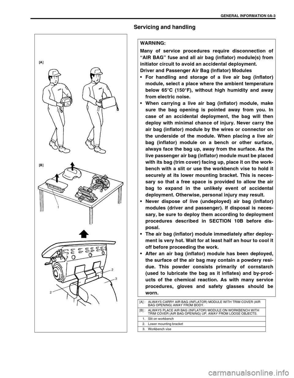
When carrying a live air bag (inflator) module, make
sure the bag opening is pointed away from you. In
case of an accidental deployment, the bag will then
deploy with minimal chance of injury. Never carry the
air bag (inflator) module by the wires or connector on
the underside of the module. When placing a live air
bag (inflator) module on a bench or other surface,
always face the bag up, away from the surface. As the
live passenger air bag (inflator) module must be placed
with its bag (trim cover) facing up, place it on the work-
bench with a slit or use the workbench vise to hold it
securely at its lower mounting bracket. This is neces-
sary so that a free space is provided to allow the air
bag to expand in the unlikely event of accidental
deployment. Otherwise, personal injury may result.
Never dispose of live (undeployed) air bag (inflator)
modules (driver and passenger). If disposal is neces-
sary, be sure to deploy them according to deployment
procedures described in SECTION 10B before dis-
posal.
The air bag (inflator) module immediately after deploy-
ment is very hot. Wait for at least half an hour to cool it
off before proceeding the work.
After an air bag (inflator) module has been deployed,
the surface of the air bag may contain a powdery resi-
due. This powder consists primarily of cornstarch
(used to lubricate the bag as it inflates) and by-prod-
ucts of the chemical reaction. As with many service
procedures, gloves and safety glasses should be
worn.
[A] : ALWAYS CARRY AIR BAG (INFLATOR) MODULE WITH TRIM COVER (AIR
BAG OPENING) AWAY FROM BODY.
[B] : ALWAYS PLACE AIR BAG (INFLATOR) MODULE ON WORKBENCH WITH
TRIM COVER (AIR BAG OPENING) UP, AWAY FROM LOOSE OBJECTS.
1. Slit on workbench
2. Lower mounting bracket
3. Workbench vise
Page 9 of 656
0A-4 GENERAL INFORMATION
WARNING:
SDM
During service procedures, be very careful when handling a Sensing and Diagnostic Module (SDM).
Never strike or jar the SDM.
Never power up the air bag system when the SDM is not rigidly attached to the vehicle. All SDM and
mounting bracket fasteners must be carefully torqued and the arrow must be pointing toward the
front of the vehicle to ensure proper operation of the air bag system.
The SDM could be activated when powered while not rigidly attached to the vehicle which could
cause deployment and result in personal injury.
WARNING:
Driver and Passenger Seat Belt Pretensioners
For handling and storage of a live seat belt preten-
sioner, select a place where the ambient temperature
below 65°C (150°F), without high humidity and away
from electric noise.
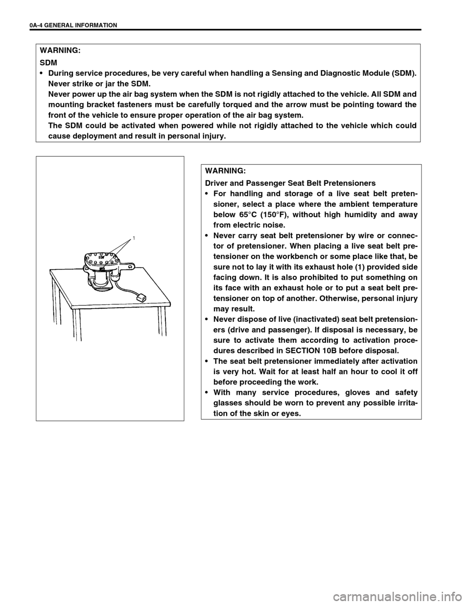
Never carry seat belt pretensioner by wire or connec-
tor of pretensioner. When placing a live seat belt pre-
tensioner on the workbench or some place like that, be
sure not to lay it with its exhaust hole (1) provided side
facing down. It is also prohibited to put something on
its face with an exhaust hole or to put a seat belt pre-
tensioner on top of another. Otherwise, personal injury
may result.
Never dispose of live (inactivated) seat belt pretension-
ers (drive and passenger). If disposal is necessary, be
sure to activate them according to activation proce-
dures described in SECTION 10B before disposal.
The seat belt pretensioner immediately after activation
is very hot. Wait for at least half an hour to cool it off
before proceeding the work.
With many service procedures, gloves and safety
glasses should be worn to prevent any possible irrita-
tion of the skin or eyes.
Page 10 of 656
GENERAL INFORMATION 0A-5
CAUTION:
Even when the accident was light enough not to cause air bags to activate, be sure to inspect sys-
tem parts and other related parts according to instructions under “REPAIR AND INSPECTION
REQUIRED AFTER AN ACCIDENT” in SECTION 10B.
When servicing parts other than air bag system, if shocks may be applied to air bag system compo-
nent parts, remove those parts beforehand.
When handling the air bag (inflator) modules (driver and passenger), forward sensors or SDM, be
careful not to drop it or apply an impact to it. If an excessive impact was applied (e.g., dropped from
a height of 91.4 cm (3 feet) or more), never attempt disassembly or repair but replace it with a new
one.
When grease, cleaning agent, oil, water, etc. has got onto air bag (inflator) modules (driver and pas-
senger), wipe off immediately with a dry cloth.
Air bag wire harness can be identified easily as it is covered with a yellow protection tube. Be very
careful when handling it.
When an open in air bag wire harness, damaged wire harness, connector or terminal is found,
replace wire harness, connectors and terminals as an assembly.
Do not apply power to the air bag system unless all components are connected or a diagnostic
chart requests it, as this will set a diagnostic trouble code.
Never use air bag system component parts from another vehicle.
When using electric welding, be sure to temporarily disable air bag system referring to “DIS-
ABLING AIR BAG SYSTEM” in SECTION 10B.
Never expose air bag system component parts directly to hot air (drying or baking the vehicle after
painting) or flames.
WARNING/CAUTION labels are attached on each part of air bag system components. Be sure to fol-
low the instructions.
After vehicle is completely repaired, perform “AIR BAG DIAGNOSTIC SYSTEM CHECK” in SEC-
TION 10B.
Page 20 of 656
MAINTENANCE AND LUBRICATION 0B-7
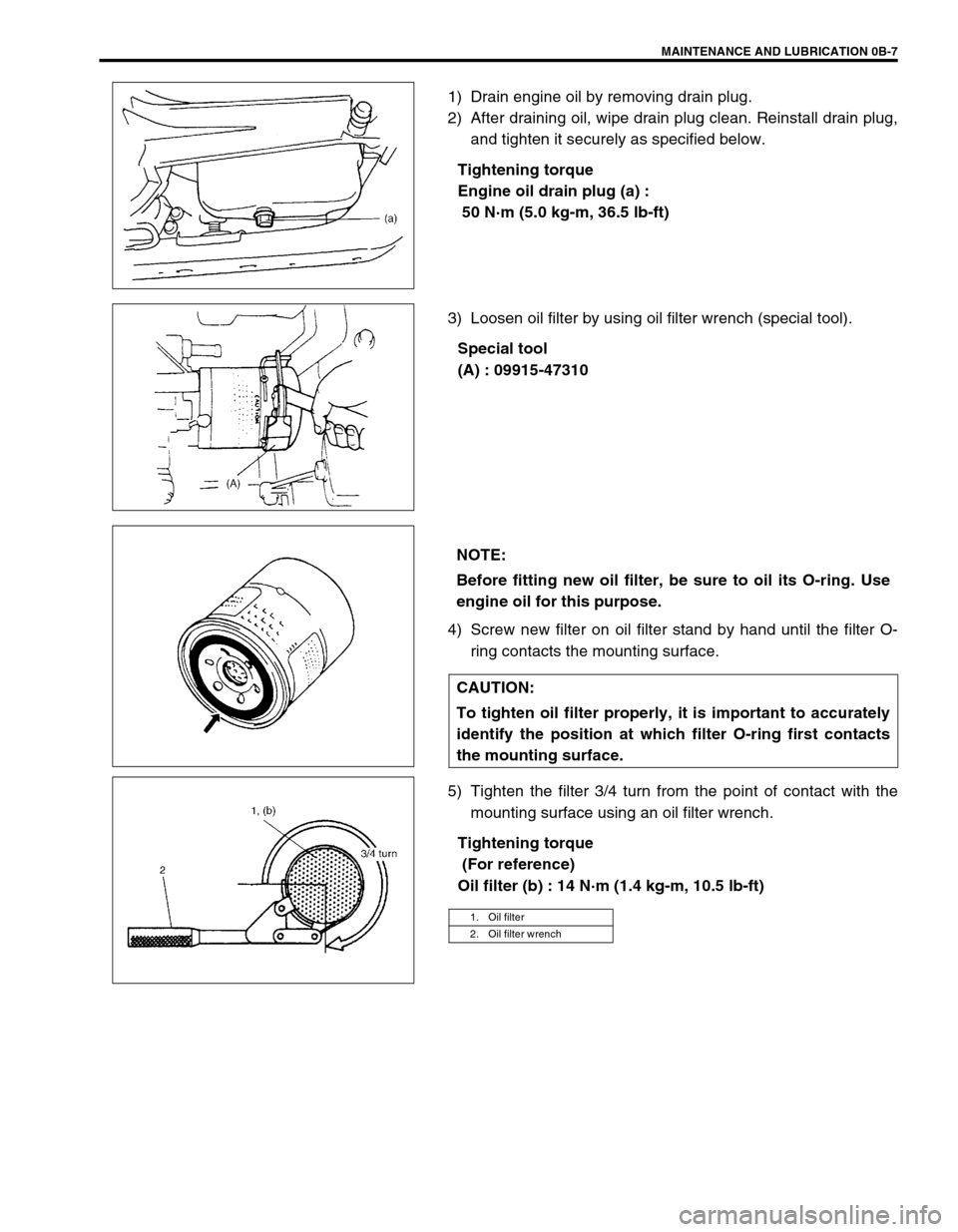
1) Drain engine oil by removing drain plug.
2) After draining oil, wipe drain plug clean. Reinstall drain plug,
and tighten it securely as specified below.
Tightening torque
Engine oil drain plug (a) :
50 N·m (5.0 kg-m, 36.5 lb-ft)
3) Loosen oil filter by using oil filter wrench (special tool).
Special tool
(A) : 09915-47310
4) Screw new filter on oil filter stand by hand until the filter O-
ring contacts the mounting surface.
5) Tighten the filter 3/4 turn from the point of contact with the
mounting surface using an oil filter wrench.
Tightening torque
(For reference)
Oil filter (b) : 14 N·m (1.4 kg-m, 10.5 lb-ft)
NOTE:
Before fitting new oil filter, be sure to oil its O-ring. Use
engine oil for this purpose.
CAUTION:
To tighten oil filter properly, it is important to accurately
identify the position at which filter O-ring first contacts
the mounting surface.
1. Oil filter
2. Oil filter wrench
Page 21 of 656
0B-8 MAINTENANCE AND LUBRICATION
6) Replenish oil until oil level is brought to FULL level mark on
dipstick. (oil pan and oil filter capacity). The filler inlet is at
the top of the cylinder head cover.
It is recommended to use engine oil of SE, SF, SG, SH or SJ
grade.
NOTE:
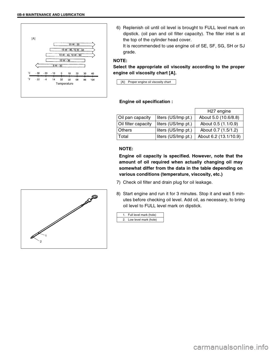
Select the appropriate oil viscosity according to the proper
engine oil viscosity chart [A].
Engine oil specification :
7) Check oil filter and drain plug for oil leakage.
8) Start engine and run it for 3 minutes. Stop it and wait 5 min-
utes before checking oil level. Add oil, as necessary, to bring
oil level to FULL level mark on dipstick.
[A]: Proper engine oil viscosity chart
H27 engine
Oil pan capacity liters (US/lmp pt.) About 5.0 (10.6/8.8)
Oil filter capacity liters (US/lmp pt.) About 0.5 (1.1/0.9)
Others liters (US/lmp pt.) About 0.7 (1.5/1.2)
Total liters (US/lmp pt.) About 6.2 (13.1/10.9)
NOTE:
Engine oil capacity is specified. However, note that the
amount of oil required when actually changing oil may
somewhat differ from the data in the table depending on
various conditions (temperature, viscosity, etc.)
1. Full level mark (hole)
2. Low level mark (hole)
Page 36 of 656
AIR CONDITIONING (OPTIONAL) 1B-11
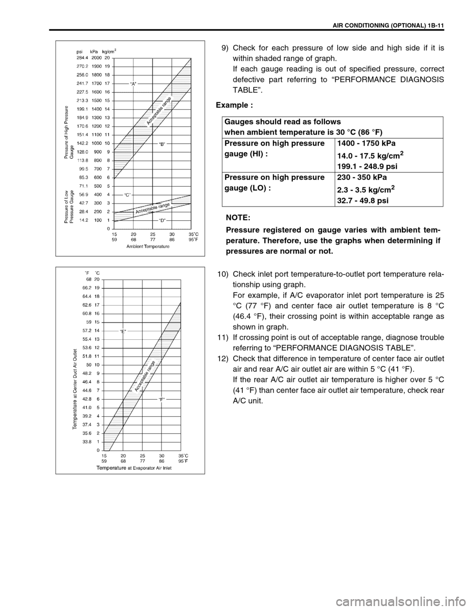
9) Check for each pressure of low side and high side if it is
within shaded range of graph.
If each gauge reading is out of specified pressure, correct
defective part referring to “PERFORMANCE DIAGNOSIS
TABLE”.
Example :
10) Check inlet port temperature-to-outlet port temperature rela-
tionship using graph.
For example, if A/C evaporator inlet port temperature is 25
°C (77 °F) and center face air outlet temperature is 8 °C
(46.4 °F), their crossing point is within acceptable range as
shown in graph.
11) If crossing point is out of acceptable range, diagnose trouble
referring to “PERFORMANCE DIAGNOSIS TABLE”.
12) Check that difference in temperature of center face air outlet
air and rear A/C air outlet air are within 5 °C (41 °F).
If the rear A/C air outlet air temperature is higher over 5 °C
(41 °F) than center face air outlet air temperature, check rear
A/C unit. Gauges should read as follows
when ambient temperature is 30 °C (86 °F)
Pressure on high pressure
gauge (HI) :1400 - 1750 kPa
14.0 - 17.5 kg/cm
2
199.1 - 248.9 psi
Pressure on high pressure
gauge (LO) :230 - 350 kPa
2.3 - 3.5 kg/cm
2
32.7 - 49.8 psi
NOTE:
Pressure registered on gauge varies with ambient tem-
perature. Therefore, use the graphs when determining if
pressures are normal or not.
Page 44 of 656
AIR CONDITIONING (OPTIONAL) 1B-19
Refrigerant Recovery, Evacuation and Charging
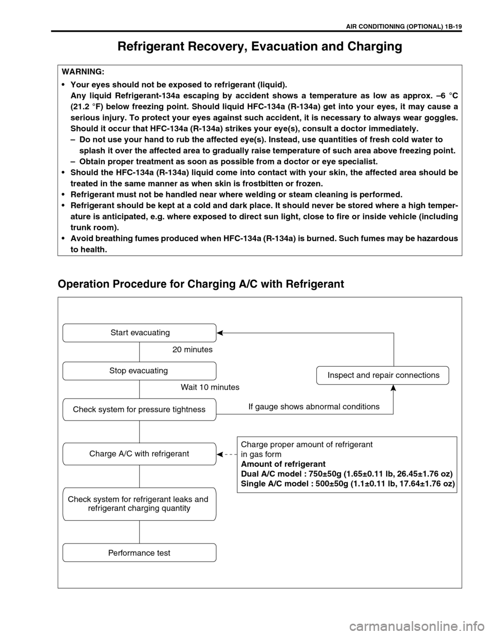
Operation Procedure for Charging A/C with Refrigerant
WARNING:
Your eyes should not be exposed to refrigerant (liquid).
Any liquid Refrigerant-134a escaping by accident shows a temperature as low as approx. –6 °C
(21.2 °F) below freezing point. Should liquid HFC-134a (R-134a) get into your eyes, it may cause a
serious injury. To protect your eyes against such accident, it is necessary to always wear goggles.
Should it occur that HFC-134a (R-134a) strikes your eye(s), consult a doctor immediately.
–Do not use your hand to rub the affected eye(s). Instead, use quantities of fresh cold water to
splash it over the affected area to gradually raise temperature of such area above freezing point.
–Obtain proper treatment as soon as possible from a doctor or eye specialist.
Should the HFC-134a (R-134a) liquid come into contact with your skin, the affected area should be
treated in the same manner as when skin is frostbitten or frozen.
Refrigerant must not be handled near where welding or steam cleaning is performed.
Refrigerant should be kept at a cold and dark place. It should never be stored where a high temper-
ature is anticipated, e.g. where exposed to direct sun light, close to fire or inside vehicle (including
trunk room).
Avoid breathing fumes produced when HFC-134a (R-134a) is burned. Such fumes may be hazardous
to health.
Start evacuating
Charge proper amount of refrigerant
in gas form
Amount of refrigerant
Dual A/C model : 750±50g (1.65±0.11 lb, 26.45±1.76 oz)
Single A/C model : 500±50g (1.1±0.11 lb, 17.64±1.76 oz)
Inspect and repair connections Stop evacuating
Performance test
Check system for pressure tightness
Charge A/C with refrigerant
Check system for refrigerant leaks and
refrigerant charging quantity
20 minutes
Wait 10 minutes
If gauge shows abnormal conditions
Page 51 of 656
1B-26 AIR CONDITIONING (OPTIONAL)
Never use heat for bending pipes. When bending a pipe, try to make its bending radius as slight as possible.
Keep internal parts of air conditioning free from moisture and dirt. When disconnecting any line from system,
install a blind plug or cap to the fitting immediately.
When tightening or loosening a fitting, use two wrenches, one for turning and the other for support.
Tighten flared nuts to specified torque.
Tightening torque
8 mm (0.31 in.) pipe : 13 N·m (1.3 kg-m, 9.5 lb-ft)
12.7 mm (0.5 in.) pipe : 22 N·m (2.2 kg-m, 16.0 lb-ft)
16 mm (0.63 in.) pipe : 33 N·m (3.3 kg-m, 24.0 lb-ft)
Route drain hose so that drained water does not make any contact to vehicle components.
Handling refrigerant HFC-134a (R-134a)
When handling refrigerant, always wear goggles to protect your eyes.
Avoid you direct contact to liquid refrigerant.
Do not heat refrigerant container higher than 40 °C (104 °F).
Do not discharge refrigerant into atmosphere.
Do not allow liquid refrigerant to touch bright metals. Refrigerant combined with moisture is corrosive and
will tarnish surfaces of bright metals including chrome.
After recovering refrigerant from system, the amount of compressor oil removed must be measured and the
same amount added to the system.
Refrigerant recovery
When discharging refrigerant out of A/C system, always recover it by using refrigerant recovery and recycling
equipment. Discharging refrigerant HFC-134a (R-134a) into atmosphere would cause adverse effect to environ-
ments.
Refrigerant charge
Charge a proper amount of refrigerant to A/C system according to charging procedure described in recovery,
evacuation and charging.NOTE:
When handling recovery and recycling equipment, be sure to follow the instruction manual for the
equipment.
CAUTION:
Do not perform an additional refrigerant charging to A/C system. This cause it to overcharge.
Page 63 of 656
1B-38 AIR CONDITIONING (OPTIONAL)
Compressor Assembly
INSPECTION
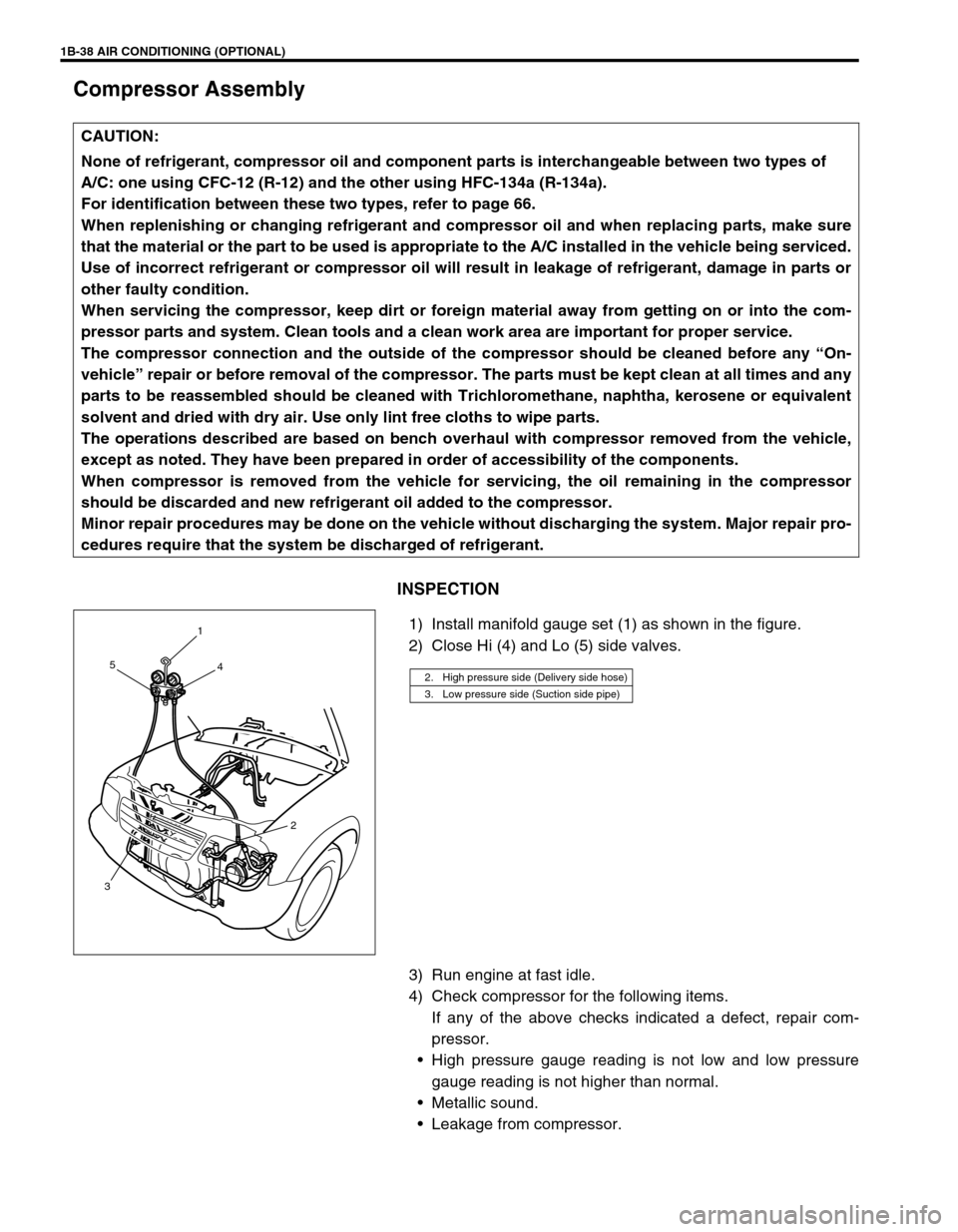
1) Install manifold gauge set (1) as shown in the figure.
2) Close Hi (4) and Lo (5) side valves.
3) Run engine at fast idle.
4) Check compressor for the following items.
If any of the above checks indicated a defect, repair com-
pressor.
High pressure gauge reading is not low and low pressure
gauge reading is not higher than normal.
Metallic sound.
Leakage from compressor. CAUTION:
None of refrigerant, compressor oil and component parts is interchangeable between two types of
A/C: one using CFC-12 (R-12) and the other using HFC-134a (R-134a).
For identification between these two types, refer to page 66.
When replenishing or changing refrigerant and compressor oil and when replacing parts, make sure
that the material or the part to be used is appropriate to the A/C installed in the vehicle being serviced.
Use of incorrect refrigerant or compressor oil will result in leakage of refrigerant, damage in parts or
other faulty condition.
When servicing the compressor, keep dirt or foreign material away from getting on or into the com-
pressor parts and system. Clean tools and a clean work area are important for proper service.
The compressor connection and the outside of the compressor should be cleaned before any “On-
vehicle” repair or before removal of the compressor. The parts must be kept clean at all times and any
parts to be reassembled should be cleaned with Trichloromethane, naphtha, kerosene or equivalent
solvent and dried with dry air. Use only lint free cloths to wipe parts.
The operations described are based on bench overhaul with compressor removed from the vehicle,
except as noted. They have been prepared in order of accessibility of the components.
When compressor is removed from the vehicle for servicing, the oil remaining in the compressor
should be discarded and new refrigerant oil added to the compressor.
Minor repair procedures may be done on the vehicle without discharging the system. Major repair pro-
cedures require that the system be discharged of refrigerant.
2. High pressure side (Delivery side hose)
3. Low pressure side (Suction side pipe)
1
4 5
2
3
Page 76 of 656
AIR BAG STEERING WHEEL AND COLUMN 3C1-1
3C1
SECTION 3C1
AIR BAG STEERING WHEEL AND COLUMN
CONTENTS
General Description ..................................... 3C1-2
Diagnosis ...................................................... 3C1-3
Inspection and Repair Required after
Accident ..................................................... 3C1-3
On-Vehicle Service....................................... 3C1-3
Service Precautions ................................... 3C1-3
Diagnosis and servicing ......................... 3C1-3
Disabling air bag system ........................ 3C1-3
Enabling air bag system ......................... 3C1-3Handling and storage ............................. 3C1-3
Disposal ................................................. 3C1-3
Steering Column ........................................ 3C1-4
Steering Upper Shaft Assembly ................. 3C1-7
Steering Lower Shaft Assembly ................. 3C1-9
Checking Steering Column and Steering
Upper Shaft for Accident Damage ........... 3C1-11
Tightening Torque Specification .............. 3C1-12
WARNING:
Service on and around the air bag system components or wiring must be performed only by an
authorized SUZUKI dealer. Please observe all WARNINGS and “Service Precautions” under “On-
Vehicle Service” in air bag system section before performing service on or around the air bag sys-
tem components or wiring. Failure to follow WARNINGS could result in unintentional activation of
the system or could render the system inoperative. Either of these two conditions may result in
severe injury.
The procedures in this section must be followed in the order listed to disable the air bag system
temporarily and prevent false diagnostic trouble codes from setting. Failure to follow procedures
could result in possible activation of the air bag system, personal injury or otherwise unneeded air
bag system repairs.
CAUTION:
When fasteners are removed, always reinstall them at the same location from which they were
removed. If a fastener needs to be replaced, use the correct part number fastener for that application.
If the correct part number fastener is not available, a fastener of equal size and strength (or stronger)
may be used. Fasteners that are not reused, and those requiring thread-locking compound, will be
called out. The correct torque value must be used when installing fasteners that require it. If the above
procedures are not followed, parts or system damage could result.
NOTE:
For the descriptions (items) not found in this section, refer to the same section of the Service Manual
mentioned in the FOREWORD of this manual.