air control SUZUKI GRAND VITARA 2001 2.G User Guide
[x] Cancel search | Manufacturer: SUZUKI, Model Year: 2001, Model line: GRAND VITARA, Model: SUZUKI GRAND VITARA 2001 2.GPages: 656, PDF Size: 14.31 MB
Page 35 of 656
1B-10 AIR CONDITIONING (OPTIONAL)
Performance Diagnosis
1) Confirm that vehicle and environmental conditions are as fol-
lows.
Vehicle is not exposed to direct sun.
Ambient temperature is within 15 - 35 °C (59 - 95 °F).
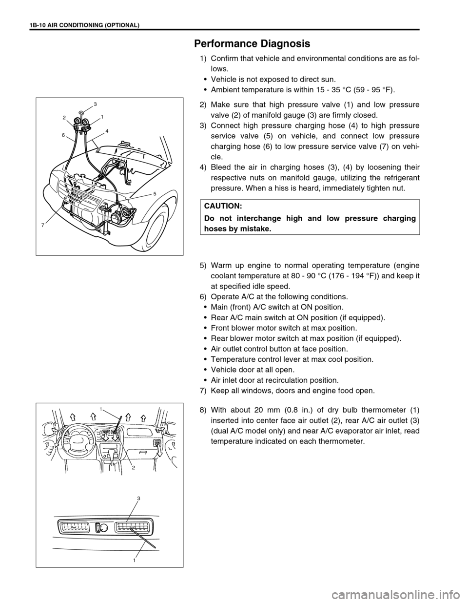
2) Make sure that high pressure valve (1) and low pressure
valve (2) of manifold gauge (3) are firmly closed.
3) Connect high pressure charging hose (4) to high pressure
service valve (5) on vehicle, and connect low pressure
charging hose (6) to low pressure service valve (7) on vehi-
cle.
4) Bleed the air in charging hoses (3), (4) by loosening their
respective nuts on manifold gauge, utilizing the refrigerant
pressure. When a hiss is heard, immediately tighten nut.
5) Warm up engine to normal operating temperature (engine
coolant temperature at 80 - 90 °C (176 - 194 °F)) and keep it
at specified idle speed.
6) Operate A/C at the following conditions.
Main (front) A/C switch at ON position.
Rear A/C main switch at ON position (if equipped).
Front blower motor switch at max position.
Rear blower motor switch at max position (if equipped).
Air outlet control button at face position.
Temperature control lever at max cool position.
Vehicle door at all open.
Air inlet door at recirculation position.
7) Keep all windows, doors and engine food open.
8) With about 20 mm (0.8 in.) of dry bulb thermometer (1)
inserted into center face air outlet (2), rear A/C air outlet (3)
(dual A/C model only) and near A/C evaporator air inlet, read
temperature indicated on each thermometer. CAUTION:
Do not interchange high and low pressure charging
hoses by mistake.
2
64
3
75 1
3
1
2
Page 39 of 656
1B-14 AIR CONDITIONING (OPTIONAL)
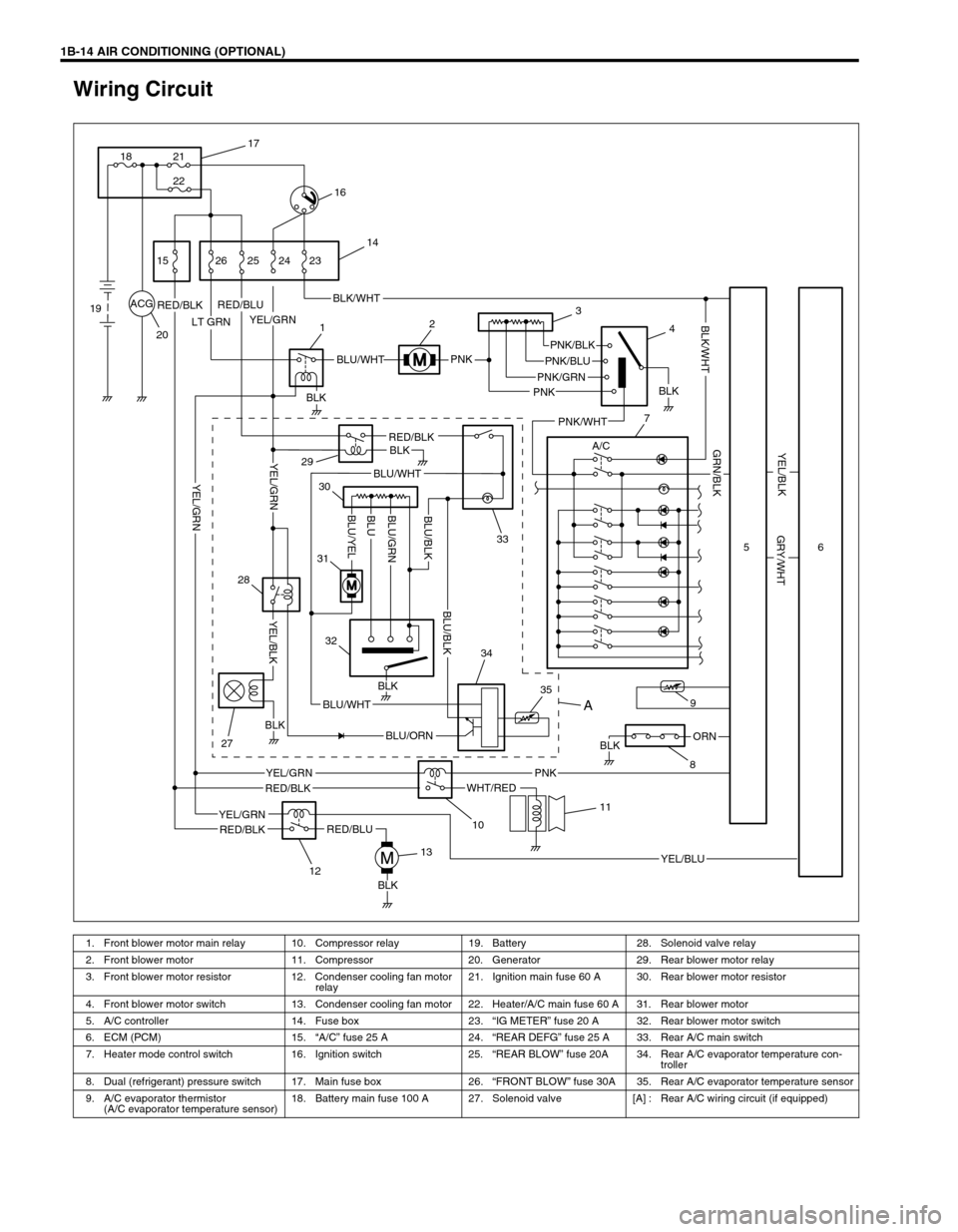
Wiring Circuit
ACG
LT GRN
PNK
PNK
BLKORN
BLK
YEL/GRNRED/BLKBLK/WHT
BLU/WHTPNK/BLK
PNK/GRN
RED/BLK
WHT/RED
YEL/GRN
YEL/BLU
A/C
RED/BLU
RED/BLU
RED/BLKBLK
BLU/ORN
BLU/WHT
BLU/WHT
PNK
PNK/BLU
BLK
PNK/WHT
YEL/BLK
GRY/WHT
GRN/BLK
BLK/WHT
RED/BLK
YEL/GRN
BLK
BLK
BLK
YEL/BLK
YEL/GRN
YEL/GRNBLU/GRN
BLU/YELBLUBLU/BLK
BLU/BLK
17
21
22 18
16
15
19
2026 25 24 23
14
12
29
3
4
7
33 30
31
32
28
27
1213
10
11
35 349
856
A
1. Front blower motor main relay 10. Compressor relay 19. Battery 28. Solenoid valve relay
2. Front blower motor 11. Compressor 20. Generator 29. Rear blower motor relay
3. Front blower motor resistor 12. Condenser cooling fan motor
relay21. Ignition main fuse 60 A 30. Rear blower motor resistor
4. Front blower motor switch 13. Condenser cooling fan motor 22. Heater/A/C main fuse 60 A 31. Rear blower motor
5. A/C controller 14. Fuse box 23.“IG METER” fuse 20 A 32. Rear blower motor switch
6. ECM (PCM) 15.“A/C” fuse 25 A 24.“REAR DEFG” fuse 25 A 33. Rear A/C main switch
7. Heater mode control switch 16. Ignition switch 25.“REAR BLOW” fuse 20A 34. Rear A/C evaporator temperature con-
troller
8. Dual (refrigerant) pressure switch 17. Main fuse box 26.“FRONT BLOW” fuse 30A 35. Rear A/C evaporator temperature sensor
9. A/C evaporator thermistor
(A/C evaporator temperature sensor)18. Battery main fuse 100 A 27. Solenoid valve [A] : Rear A/C wiring circuit (if equipped)
Page 40 of 656
AIR CONDITIONING (OPTIONAL) 1B-15
Inspection of A/C Controller and Its Circuits
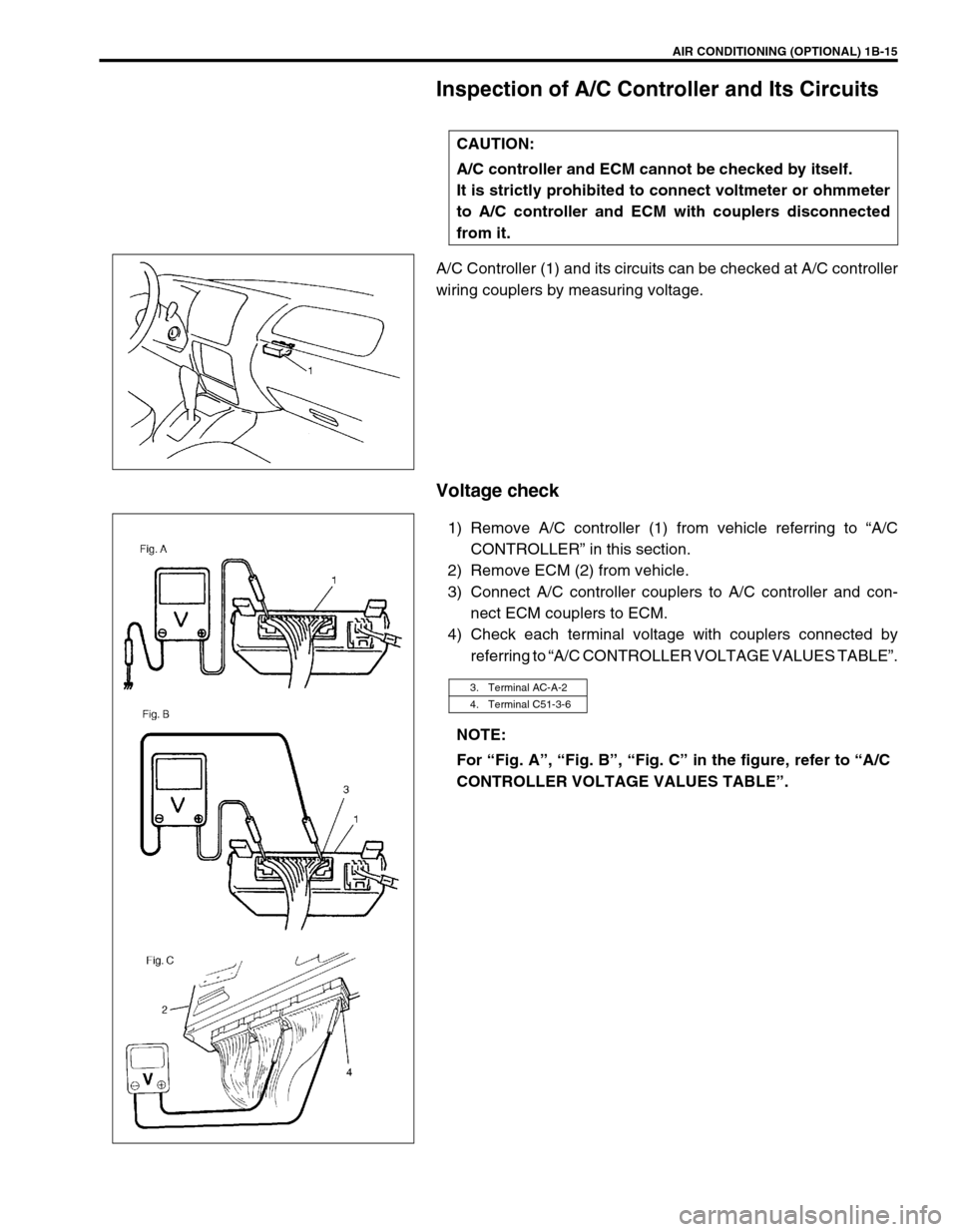
A/C Controller (1) and its circuits can be checked at A/C controller
wiring couplers by measuring voltage.
Voltage check
1) Remove A/C controller (1) from vehicle referring to “A/C
CONTROLLER” in this section.
2) Remove ECM (2) from vehicle.
3) Connect A/C controller couplers to A/C controller and con-
nect ECM couplers to ECM.
4) Check each terminal voltage with couplers connected by
referring to “A/C CONTROLLER VOLTAGE VALUES TABLE”. CAUTION:
A/C controller and ECM cannot be checked by itself.
It is strictly prohibited to connect voltmeter or ohmmeter
to A/C controller and ECM with couplers disconnected
from it.
3. Terminal AC-A-2
4. Terminal C51-3-6
NOTE:
For “Fig. A”, “Fig. B”, “Fig. C” in the figure, refer to “A/C
CONTROLLER VOLTAGE VALUES TABLE”.
Page 41 of 656
1B-16 AIR CONDITIONING (OPTIONAL)
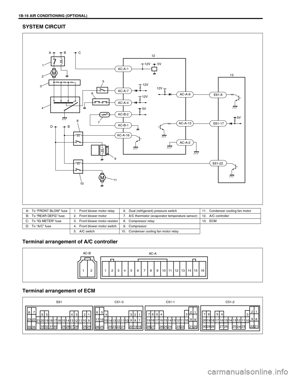
SYSTEM CIRCUIT
Terminal arrangement of A/C controller
Terminal arrangement of ECM
A: To “FRONT BLOW” fuse 1. Front blower motor relay 6. Dual (refrigerant) pressure switch 11. Condenser cooling fan motor
B: To “REAR DEFG” fuse 2. Front blower motor 7. A/C thermistor (evaporator temperature sensor) 12. A/C controller
C: To “IG METER” fuse 3. Front blower motor resistor 8. Compressor relay 13. ECM
D: To “A/C” fuse 4. Front blower motor switch 9. Compressor
5. A/C switch 10. Condenser cooling fan motor relay
5V
12V12V
12V5V
12V
5V
AC-A-1
AC-A-7
AC-A-4
AC-B-2
AC-B-1
AC-A-16AC-A-9
AC-A-2 AC-A-13
E61-8
E61-17
E61-22
A
DBBC
1
2
3
4
7 865
1011912
13
12 12
3
45 6 7 8 9 101112131415 16 AC-B
AC-A
87
22 23
34
3565
16 17
25
262
1
8 9
20
212
1
8 9
21
22 1 2 3 4 5 6
9
24 25 26 27 28 29 30 31 32 3310 11
12 13 14 15 16 17 18 19 20 211 2 3 4
7 8 9
10 11 12 13 14 15
18 19 20 21 22 23 243 4 5 6 7
10 11 12 13 14 15 16 17 18 19
22 23 24 25 26
27 283 4 5 6 7
10 11 12 13 14 15 16 19 18 2017
23
24 25 26 27 29 28 30 E61 C51-3 C51-1 C51-2
Page 42 of 656
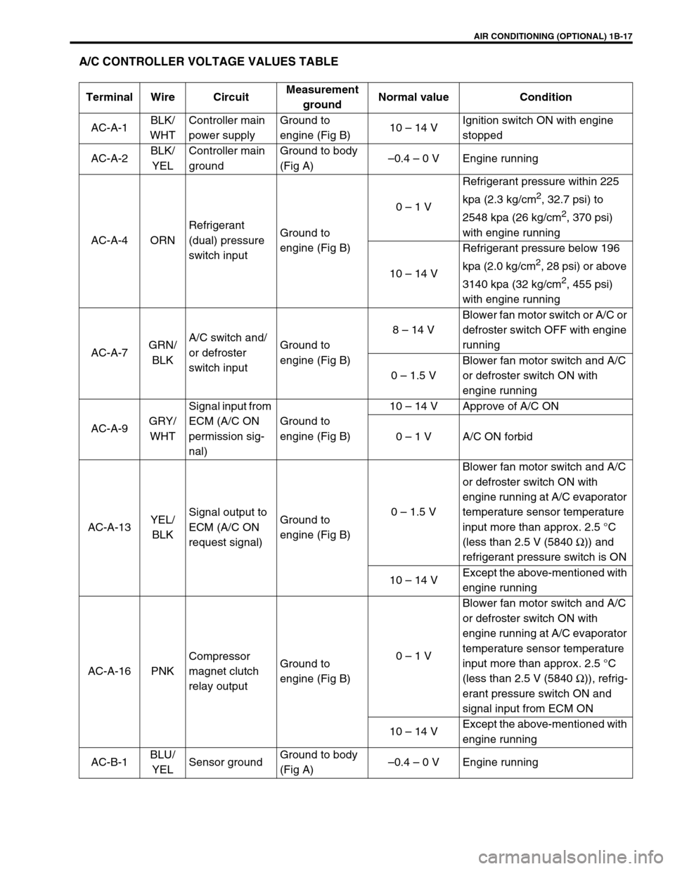
AIR CONDITIONING (OPTIONAL) 1B-17
A/C CONTROLLER VOLTAGE VALUES TABLE
Terminal Wire CircuitMeasurement
groundNormal value Condition
AC-A-1BLK/
WHTController main
power supplyGround to
engine (Fig B)10 – 14 VIgnition switch ON with engine
stopped
AC-A-2BLK/
YELController main
groundGround to body
(Fig A)–0.4 – 0 V Engine running
AC-A-4 ORNRefrigerant
(dual) pressure
switch inputGround to
engine (Fig B)0 – 1 VRefrigerant pressure within 225
kpa (2.3 kg/cm
2, 32.7 psi) to
2548 kpa (26 kg/cm
2, 370 psi)
with engine running
10 – 14 VRefrigerant pressure below 196
kpa (2.0 kg/cm
2, 28 psi) or above
3140 kpa (32 kg/cm
2, 455 psi)
with engine running
AC-A-7GRN/
BLKA/C switch and/
or defroster
switch inputGround to
engine (Fig B)8 – 14 VBlower fan motor switch or A/C or
defroster switch OFF with engine
running
0 – 1.5 VBlower fan motor switch and A/C
or defroster switch ON with
engine running
AC-A-9GRY/
WHTSignal input from
ECM (A/C ON
permission sig-
nal)Ground to
engine (Fig B)10 – 14 V Approve of A/C ON
0 – 1 V A/C ON forbid
AC-A-13YEL/
BLKSignal output to
ECM (A/C ON
request signal)Ground to
engine (Fig B)0 – 1.5 VBlower fan motor switch and A/C
or defroster switch ON with
engine running at A/C evaporator
temperature sensor temperature
input more than approx. 2.5 °C
(less than 2.5 V (5840 Ω)) and
refrigerant pressure switch is ON
10 – 14 VExcept the above-mentioned with
engine running
AC-A-16 PNKCompressor
magnet clutch
relay outputGround to
engine (Fig B)0 – 1 VBlower fan motor switch and A/C
or defroster switch ON with
engine running at A/C evaporator
temperature sensor temperature
input more than approx. 2.5 °C
(less than 2.5 V (5840 Ω)), refrig-
erant pressure switch ON and
signal input from ECM ON
10 – 14 VExcept the above-mentioned with
engine running
AC-B-1BLU/
YELSensor groundGround to body
(Fig A)–0.4 – 0 V Engine running
Page 43 of 656
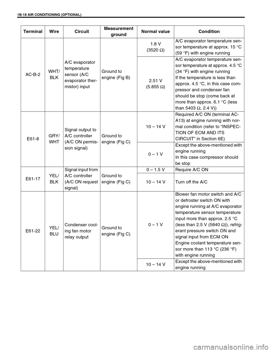
1B-18 AIR CONDITIONING (OPTIONAL)
Terminal Wire CircuitMeasurement
groundNormal value Condition
AC-B-2WHT/
BLKA/C evaporator
temperature
sensor (A/C
evaporator ther-
mistor) inputGround to
engine (Fig B)1.8 V
(3520 Ω)A/C evaporator temperature sen-
sor temperature at approx. 15 °C
(59 °F) with engine running
2.51 V
(5.855 Ω)A/C evaporator temperature sen-
sor temperature at approx. 4.5 °C
(34 °F) with engine running
If the temperature is less than
approx. 4.5 °C, in this case com-
pressor and condenser fan
should be stop (come back at
more than approx. 6.1 °C (less
than 5403 Ω, 2.4 V))
E61-8GRY/
WHTSignal output to
A/C controller
(A/C ON permis-
sion signal)Ground to
engine (Fig C)10 – 14 VRequired A/C ON (terminal AC-
A13) at engine running with nor-
mal condition (refer to “INSPEC-
TION OF ECM AND ITS
CIRCUIT” in Section 6E)
0 – 1 VExcept the above-mentioned with
engine running
In this case compressor should
be stop
E61-17YEL/
BLKSignal input from
A/C controller
(A/C ON request
signal)Ground to
engine (Fig C)0 – 1.5 V Require A/C ON
10 – 14 V Turn off the A/C
E61-22YEL/
BLUCondenser cool-
ing fan motor
relay outputGround to
engine (Fig C)0 – 1 VBlower fan motor switch and A/C
or defroster switch ON with
engine running at A/C evaporator
temperature sensor temperature
input more than approx. 2.5 °C
(less than 2.5 V (5840 Ω)), refrig-
erant pressure switch ON and
signal input from ECM ON
Engine coolant temperature sen-
sor more than 113 °C (236 °F)
with engine running
10 – 14 VExcept the above-mentioned with
engine running
Page 53 of 656
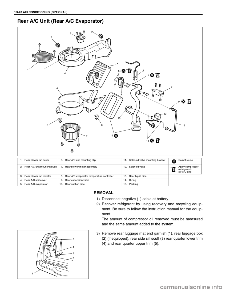
1B-28 AIR CONDITIONING (OPTIONAL)
Rear A/C Unit (Rear A/C Evaporator)
REMOVAL
1) Disconnect negative (–) cable at battery.
2) Recover refrigerant by using recovery and recycling equip-
ment. Be sure to follow the instruction manual for the equip-
ment.
The amount of compressor oil removed must be measured
and the same amount added to the system.
3) Remove rear luggage mat end garnish (1), rear luggage box
(2) (if equipped), rear side sill scuff (3) rear quarter lower trim
(4) and rear quarter upper trim (5).
1. Rear blower fan cover 6. Rear A/C unit mounting clip 11. Solenoid valve mounting bracket Do not reuse
2. Rear A/C unit mounting bush 7. Rear blower motor assembly 12. Solenoid valve Apply compressor
(refrigerant)
oil to O-ring
3. Rear blower fan resistor 8. Rear A/C evaporator temperature controller 13. Rear liquid pipe
4. Rear A/C unit cover 9. Rear expansion valve 14. O-ring
5. Rear A/C evaporator 10. Rear suction pipe 15. Packing
6
7
15
10
14
12
13
14
14
14
11
8
9
4
6
5
41
232
5
4
3
2
1
Page 55 of 656
1B-30 AIR CONDITIONING (OPTIONAL)
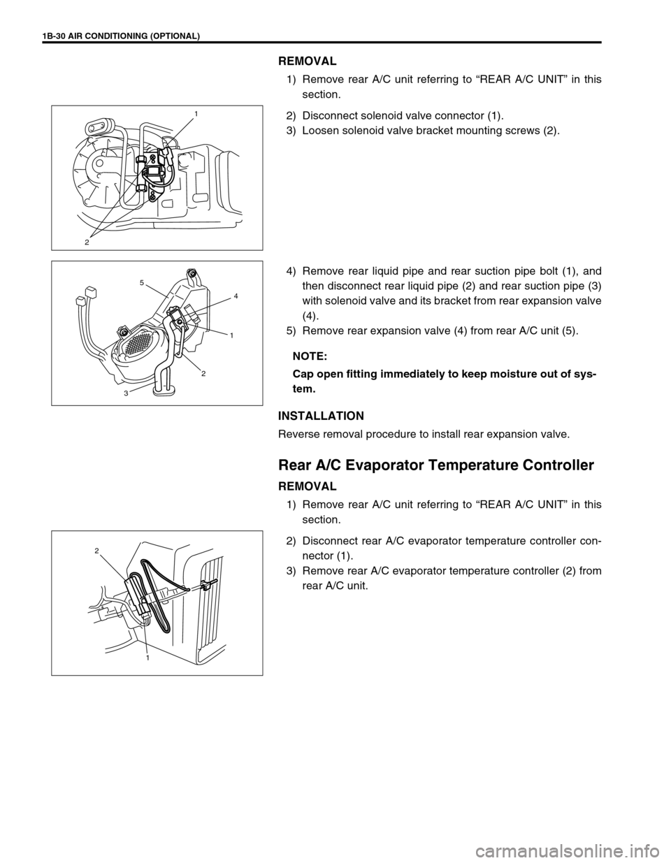
REMOVAL
1) Remove rear A/C unit referring to “REAR A/C UNIT” in this
section.
2) Disconnect solenoid valve connector (1).
3) Loosen solenoid valve bracket mounting screws (2).
4) Remove rear liquid pipe and rear suction pipe bolt (1), and
then disconnect rear liquid pipe (2) and rear suction pipe (3)
with solenoid valve and its bracket from rear expansion valve
(4).
5) Remove rear expansion valve (4) from rear A/C unit (5).
INSTALLATION
Reverse removal procedure to install rear expansion valve.
Rear A/C Evaporator Temperature Controller
REMOVAL
1) Remove rear A/C unit referring to “REAR A/C UNIT” in this
section.
2) Disconnect rear A/C evaporator temperature controller con-
nector (1).
3) Remove rear A/C evaporator temperature controller (2) from
rear A/C unit.
21
NOTE:
Cap open fitting immediately to keep moisture out of sys-
tem.
4
1
2
3
5
1 2
Page 56 of 656
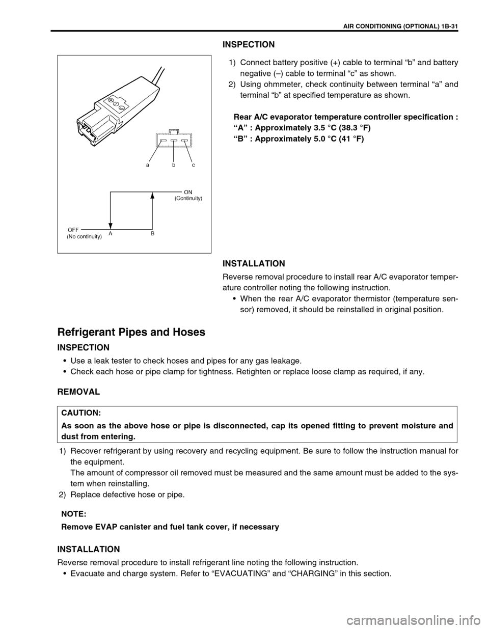
AIR CONDITIONING (OPTIONAL) 1B-31
INSPECTION
1) Connect battery positive (+) cable to terminal “b” and battery
negative (–) cable to terminal “c” as shown.
2) Using ohmmeter, check continuity between terminal “a” and
terminal “b” at specified temperature as shown.
Rear A/C evaporator temperature controller specification :
“A” : Approximately 3.5 °C (38.3 °F)
“B” : Approximately 5.0 °C (41 °F)
INSTALLATION
Reverse removal procedure to install rear A/C evaporator temper-
ature controller noting the following instruction.
When the rear A/C evaporator thermistor (temperature sen-
sor) removed, it should be reinstalled in original position.
Refrigerant Pipes and Hoses
INSPECTION
Use a leak tester to check hoses and pipes for any gas leakage.
Check each hose or pipe clamp for tightness. Retighten or replace loose clamp as required, if any.
REMOVAL
1) Recover refrigerant by using recovery and recycling equipment. Be sure to follow the instruction manual for
the equipment.
The amount of compressor oil removed must be measured and the same amount must be added to the sys-
tem when reinstalling.
2) Replace defective hose or pipe.
INSTALLATION
Reverse removal procedure to install refrigerant line noting the following instruction.
Evacuate and charge system. Refer to “EVACUATING” and “CHARGING” in this section.
CAUTION:
As soon as the above hose or pipe is disconnected, cap its opened fitting to prevent moisture and
dust from entering.
NOTE:
Remove EVAP canister and fuel tank cover, if necessary
Page 74 of 656

POWER STEERING (P/S) SYSTEM 3B1-3
Hydraulic Pressure in P/S Circuit
Hydraulic pressure check
1) After cleaning joint of high pressure hose and P/S pump
thoroughly, disconnect hose from pump and install special
tool (oil pressure gauge, attachment and hose).
Special tool
(A) : 09915-77410
(B) : 09915-77420
2) Check each connection for fluid leakage and bleed air.
Refer to “AIR BLEEDING PROCEDURE” in this section.
3) With engine idling, turn steering wheel and warm up engine
till temperature of fluid in P/S fluid reservoir rises to 50 –
60°C (122 – 140°F).
4) Check back pressure by measuring hydraulic pressure with
engine idling and hands off steering wheel.
When back pressure is higher than specified values, check
control valve and piping for clogging.
Back pressure :
Lower than 1000 kPa (10 kg/cm
2, 142 psi) CAUTION:
Take care not to cause damage to A/C condenser during
service operation, if equipped.
1. P/S fluid reservoir
2. Attachment
3. Gasket
4. Union bolt
5. High pressure side
6. Low pressure side
1. P/S fluid reservoir 4. P/S gear box
2. Gauge valve (open) 5. High pressure side
3. P/S pump 6. Low pressure side