Steering SUZUKI GRAND VITARA 2001 2.G Owner's Manual
[x] Cancel search | Manufacturer: SUZUKI, Model Year: 2001, Model line: GRAND VITARA, Model: SUZUKI GRAND VITARA 2001 2.GPages: 656, PDF Size: 14.31 MB
Page 85 of 656
3C1-10 AIR BAG STEERING WHEEL AND COLUMN
INSTALLATION
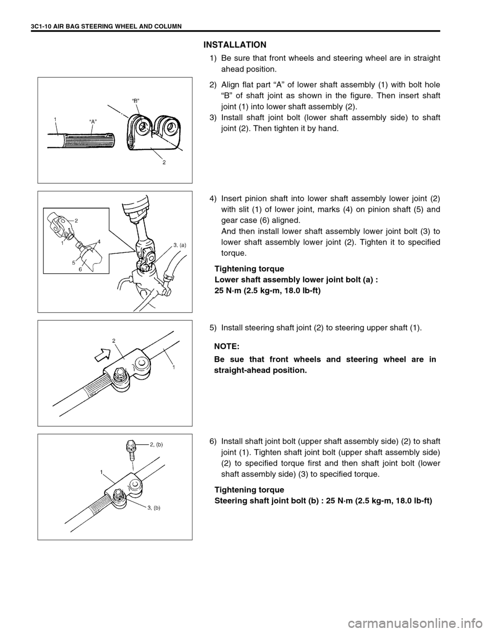
1) Be sure that front wheels and steering wheel are in straight
ahead position.
2) Align flat part “A” of lower shaft assembly (1) with bolt hole
“B” of shaft joint as shown in the figure. Then insert shaft
joint (1) into lower shaft assembly (2).
3) Install shaft joint bolt (lower shaft assembly side) to shaft
joint (2). Then tighten it by hand.
4) Insert pinion shaft into lower shaft assembly lower joint (2)
with slit (1) of lower joint, marks (4) on pinion shaft (5) and
gear case (6) aligned.
And then install lower shaft assembly lower joint bolt (3) to
lower shaft assembly lower joint (2). Tighten it to specified
torque.
Tightening torque
Lower shaft assembly lower joint bolt (a) :
25 N·m (2.5 kg-m, 18.0 lb-ft)
5) Install steering shaft joint (2) to steering upper shaft (1).
6) Install shaft joint bolt (upper shaft assembly side) (2) to shaft
joint (1). Tighten shaft joint bolt (upper shaft assembly side)
(2) to specified torque first and then shaft joint bolt (lower
shaft assembly side) (3) to specified torque.
Tightening torque
Steering shaft joint bolt (b) : 25 N·m (2.5 kg-m, 18.0 lb-ft)
NOTE:
Be sue that front wheels and steering wheel are in
straight-ahead position.
Page 86 of 656

AIR BAG STEERING WHEEL AND COLUMN 3C1-11
Checking Steering Column and Steering
Upper Shaft for Accident Damage
Check that 2 capsules are attached to steering column
bracket securely. Check clearance between capsules and
steering column bracket. Clearance should be 0 mm (0 in.)
on both sides. If found loose or clearance, replace steering
column assembly.
Take measurement “a” as shown in the figure. If it is shorter
than specified length, replace column assembly with new
one.
Steering column assembly length “a” :
490.3 ± 1.0 mm (19.30 ± 0.04 in.)
Check steering shaft for smooth rotation.
If found defective, replace as column assembly.
Check steering shaft and column for bend, cracks or defor-
mation.
If found defective, replace as column assembly.
Check steering upper shaft lower seal (1) for breakage or
deformation.
If found defective, replace.
Check steering shaft joints and shaft for any damages such
as crack, breakage, malfunction or excessive play.
If anything is found faulty, replace steering upper shaft
assembly, steering lower shaft assembly or steering column
assembly. NOTE:
Vehicles involved in accidents resulting in body damage,
where steering column has been impacted or air bag
deployed, may have a damaged or misaligned steering
column.
1. Capsule
2. Steering column bracket
1
2
“a”
Page 87 of 656
3C1-12 AIR BAG STEERING WHEEL AND COLUMN
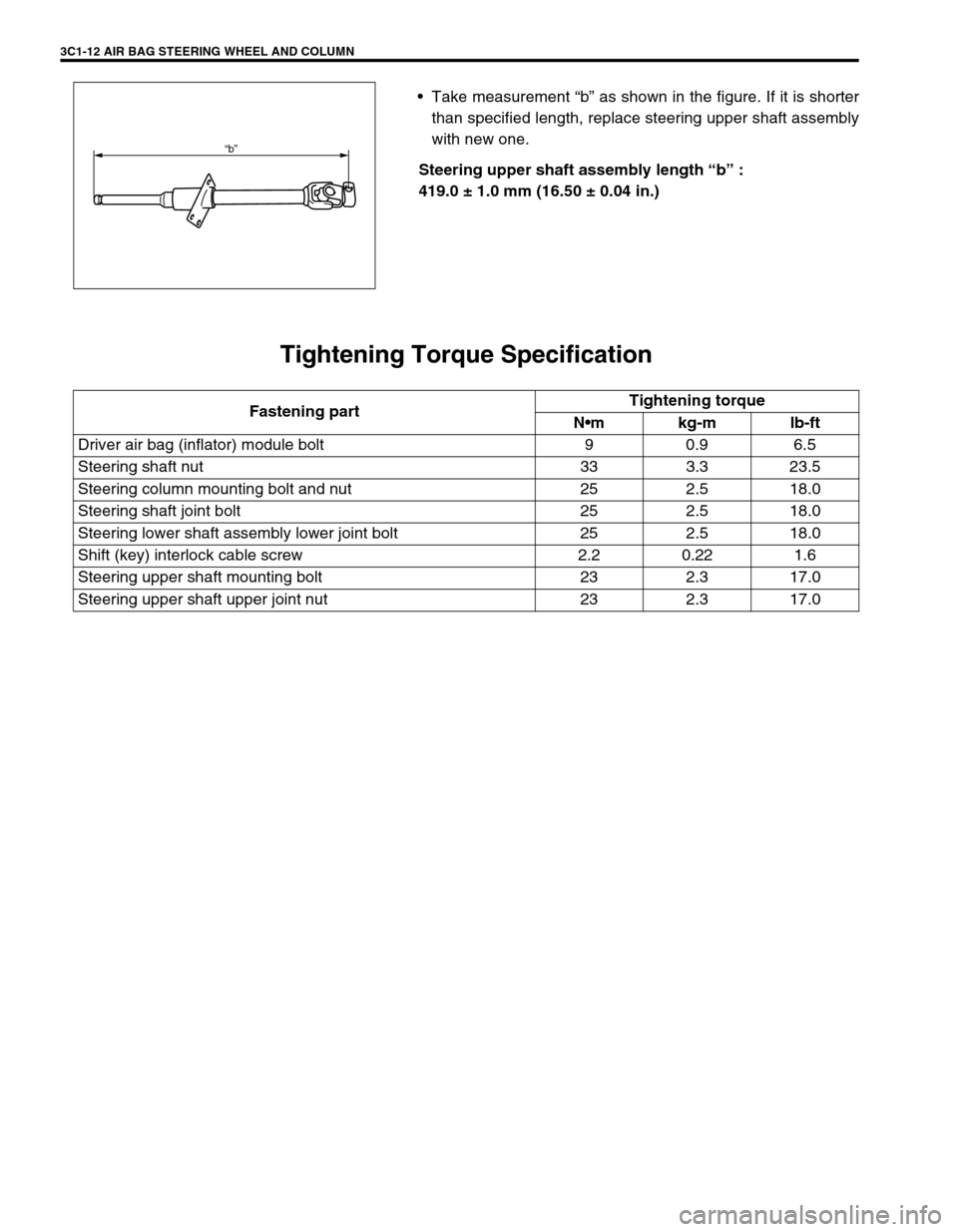
Take measurement “b” as shown in the figure. If it is shorter
than specified length, replace steering upper shaft assembly
with new one.
Steering upper shaft assembly length “b” :
419.0 ± 1.0 mm (16.50 ± 0.04 in.)
Tightening Torque Specification
“b”
Fastening partTightening torque
Nm kg-m lb-ft
Driver air bag (inflator) module bolt 9 0.9 6.5
Steering shaft nut 33 3.3 23.5
Steering column mounting bolt and nut 25 2.5 18.0
Steering shaft joint bolt 25 2.5 18.0
Steering lower shaft assembly lower joint bolt 25 2.5 18.0
Shift (key) interlock cable screw 2.2 0.22 1.6
Steering upper shaft mounting bolt 23 2.3 17.0
Steering upper shaft upper joint nut 23 2.3 17.0
Page 110 of 656
BRAKES PIPE/HOSE/MASTER CYLINDER 5A-3
On-Vehicle Service
Front Brake Hose/Pipe
REMOVAL
1) Raise and suitably support vehicle. Remove tire and wheel.
This operation is not necessary when removing pipes connecting master cylinder and flexible hose.
2) Clean dirt and foreign material from both hose end or pipe end fittings. Remove brake hose or pipe.
INSTALLATION
1) Reverse removal procedure for brake hose and pipe installation procedure.
For installation, make sure that steering wheel is in straightforward position and hose has no twist or kink.
Check to make sure that hose doesn't contact any part of suspension, both in extreme right and extreme left
turn conditions. If it does at any point, remove and correct. Fill and maintain brake fluid level in reservoir.
Bleed brake system.
2) Perform brake test and check installed part for fluid leakage.
Tightening torque
Brake pipe flare nut (a) : 16 N·m (1.6 kg-m, 12.0 lb-ft)
Brake flexible hose bolt (brake caliper/2 joint) (b) : 23 N·m (2.3 kg-m, 17.0 lb-ft)
2-way joint mounting bolt (c) : 10 N·m (1.0 kg-m, 7.5 lb-ft)
Brake hose/pipe bracket bolt (c) : 10 N·m (1.0 kg-m, 7.5 lb-ft)
ABS actuator bracket bolt (c) : 10 N·m (1.0 kg-m, 7.5 lb-ft)
ABS actuator mounting bolt (d) : 9 N·m (0.9 kg-m, 6.5 lb-ft)
NOTE:
Insert E-ring till its end surface is flush with or lower than bracket end surface.
Page 111 of 656

5A-4 BRAKES PIPE/HOSE/MASTER CYLINDER
For RH steering vehicle
[D]: View D 1. E-ring
[a]: Clamp a 2. Flexible hose
[b]: Clamp b 3. Hose washer
[c]: Clamp d 4. Hose bolt
T: Top side 5. Brake caliper
F: Front side 6. 2 way joint
Page 112 of 656

BRAKES PIPE/HOSE/MASTER CYLINDER 5A-5
For LH steering vehicle
[D]: View D 1. E-ring
[a]: Clamp a 2. Flexible hose
[b]: Clamp b 3. Hose washer
[d]: Clamp d 4. Hose bolt
T: Top side 5. Brake caliper
F: Front side 6. 2 way joint
Page 128 of 656
ANTILOCK BRAKE SYSTEM (ABS) 5E2-3
General Description
Components/Parts Location
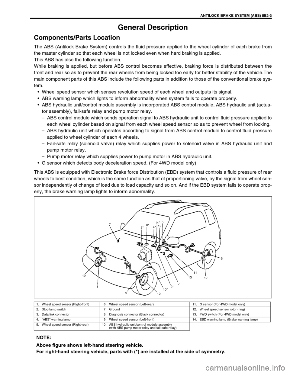
The ABS (Antilock Brake System) controls the fluid pressure applied to the wheel cylinder of each brake from
the master cylinder so that each wheel is not locked even when hard braking is applied.
This ABS has also the following function.
While braking is applied, but before ABS control becomes effective, braking force is distributed between the
front and rear so as to prevent the rear wheels from being locked too early for better stability of the vehicle.The
main component parts of this ABS include the following parts in addition to those of the conventional brake sys-
tem.
Wheel speed sensor which senses revolution speed of each wheel and outputs its signal.
ABS warning lamp which lights to inform abnormality when system fails to operate properly.
ABS hydraulic unit/control module assembly is incorporated ABS control module, ABS hydraulic unit (actua-
tor assembly), fail-safe relay and pump motor relay.
–ABS control module which sends operation signal to ABS hydraulic unit to control fluid pressure applied to
each wheel cylinder based on signal from each wheel speed sensor so as to prevent wheel from locking.
–ABS hydraulic unit which operates according to signal from ABS control module to control fluid pressure
applied to wheel cylinder of each 4 wheels.
–Fail-safe relay (solenoid valve) relay which supplies power to solenoid valve in ABS hydraulic unit and
pump motor relay.
–Pump motor relay which supplies power to pump motor in ABS hydraulic unit.
G sensor which detects body deceleration speed. (For 4WD model only)
This ABS is equipped with Electronic Brake force Distribution (EBD) system that controls a fluid pressure of rear
wheels to best condition, which is the same function as that of proportioning valve, by the signal from wheel sen-
sor independently of change of load due to load capacity and so on. And if the EBD system fails to operate prop-
erly, the brake warning lamp lights to inform abnormality.
1. Wheel speed sensor (Right-front) 6. Wheel speed sensor (Left-rear) 11. G sensor (For 4WD model only)
2. Stop lamp switch 7. Ground 12. Wheel speed sensor rotor (ring)
3. Data link connector 8. Diagnosis connector (Black connector) 13. 4WD switch (For 4WD model only)
4.“ABS” warning lamp 9. Wheel speed sensor (Left-front) 14. EBD warning lamp (Brake warning lamp)
5. Wheel speed sensor (Right-rear) 10. ABS hydraulic unit/control module assembly
(with ABS pump motor relay and fail-safe relay)
NOTE:
Above figure shows left-hand steering vehicle.
For right-hand steering vehicle, parts with (*) are installed at the side of symmetry.
Page 166 of 656
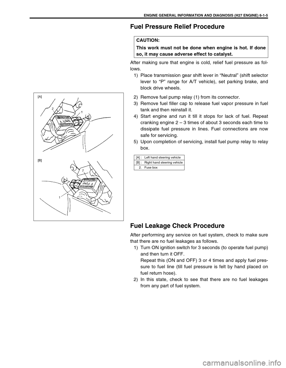
ENGINE GENERAL INFORMATION AND DIAGNOSIS (H27 ENGINE) 6-1-5
Fuel Pressure Relief Procedure
After making sure that engine is cold, relief fuel pressure as fol-
lows.
1) Place transmission gear shift lever in “Neutral” (shift selector
lever to “P” range for A/T vehicle), set parking brake, and
block drive wheels.
2) Remove fuel pump relay (1) from its connector.
3) Remove fuel filler cap to release fuel vapor pressure in fuel
tank and then reinstall it.
4) Start engine and run it till it stops for lack of fuel. Repeat
cranking engine 2 – 3 times of about 3 seconds each time to
dissipate fuel pressure in lines. Fuel connections are now
safe for servicing.
5) Upon completion of servicing, install fuel pump relay to relay
box.
Fuel Leakage Check Procedure
After performing any service on fuel system, check to make sure
that there are no fuel leakages as follows.
1) Turn ON ignition switch for 3 seconds (to operate fuel pump)
and then turn it OFF.
Repeat this (ON and OFF) 3 or 4 times and apply fuel pres-
sure to fuel line (till fuel pressure is felt by hand placed on
fuel return hose).
2) In this state, check to see that there are no fuel leakages
from any part of fuel system. CAUTION:
This work must not be done when engine is hot. If done
so, it may cause adverse effect to catalyst.
[A] : Left hand steering vehicle
[B] : Right hand steering vehicle
2. Fuse box
Page 186 of 656

ENGINE GENERAL INFORMATION AND DIAGNOSIS (H27 ENGINE) 6-1-25
INJ PULSE WIDTH B2 At specified idle speed with no load after
warming up.2.0 – 3.3 msec
✱
At 2500 r/min with no load after warming up. 2.2 – 3.2 msec
THROTTLE POS
(Absolute Throttle Posi-
tion)With ignition switch ON/warmed up engine
stopped, accelerator pedal released9.8 – 18.2 %
With ignition switch ON/warmed up engine
stopped, accelerator pedal depressed fully72 – 87.2 %
TP SENSOR VOLT
(TP Sensor Output Volt-
age)With ignition switch ON/warmed up engine
stopped, accelerator pedal released0.49 – 0.91 V
✱
With ignition switch ON/warmed up engine
stopped, accelerator pedal depressed fully.3.76 – 4.36 V
O2S B1 S1
(HO2S-1 Output Voltage)At specified idle speed after warming up
0.05 – 0.95 V
O2S B1 S2
(HO2S-2 Output Voltage)When engine is running at 2000 r/min. for 3
min or longer after warming up.0.05 – 0.95 V
O2S B2 S1
(HO2S-2 Output Voltage)When engine is running at 2000 r/min. for 3
min or longer after warming up.0.05 – 0.95 V
O2S B2 S2
(HO2S-2 Output Voltage)When engine is running at 2000 r/min. for 3
min or longer after warming up.0.05 – 0.95 V
FUEL SYSTEM B1
(Fuel System Status)At specified idle speed after warming up.
Closed✱
FUEL SYSTEM B2
(Fuel System Status)At specified idle speed after warming up.
Closed
CALC LOAD
(Calculated Load Value)At specified idle speed with no load after
warming up.10 – 25 %
At 2500 r/min with no load after warming up. 14 – 23 %
TOTAL FT TRIM B1 At specified idle speed after warming up. –30 – +30 %✱
TOTAL FT TRIM B2 At specified idle speed after warming up. –30 – +30 %
MAP At specified idle speed after warming up. 25 – 35 kPa
CANIST PRG DUTY
(EVAP Canister Purge
Flow Duty)At specified idle speed after warming up.
0 %✱
VEHICLE SPEED. At stop. 0 km/h 0 MPH
FUEL CUT When engine is at fuel cut condition ON
✱
Other than fuel cut condition OFF
EGR VALVE At specified idle speed after warming up 0 %✱
BLOWER FAN Ignition switch ON, blower fan switch ON ON
✱
Ignition switch ON, blower fan switch OFF OFF
A/C CONDENSER FAN Ignition switch ON, A/C not operating OFF
✱
Ignition switch ON, A/C operating ON
PSP SWITCH Engine running at idle speed and steering
wheel at straight ahead positionOFF
✱
Engine running at idle speed and steering
wheel turned to the right or left as far as it
stopsON
A/C SWITCH
(if equipped)When A/C not operating OFF
✱
When A/C operating ON SCAN TOOL DATA CONDITIONNORMAL CONDITION/
REFERENCE VALUEOTHER
Page 201 of 656
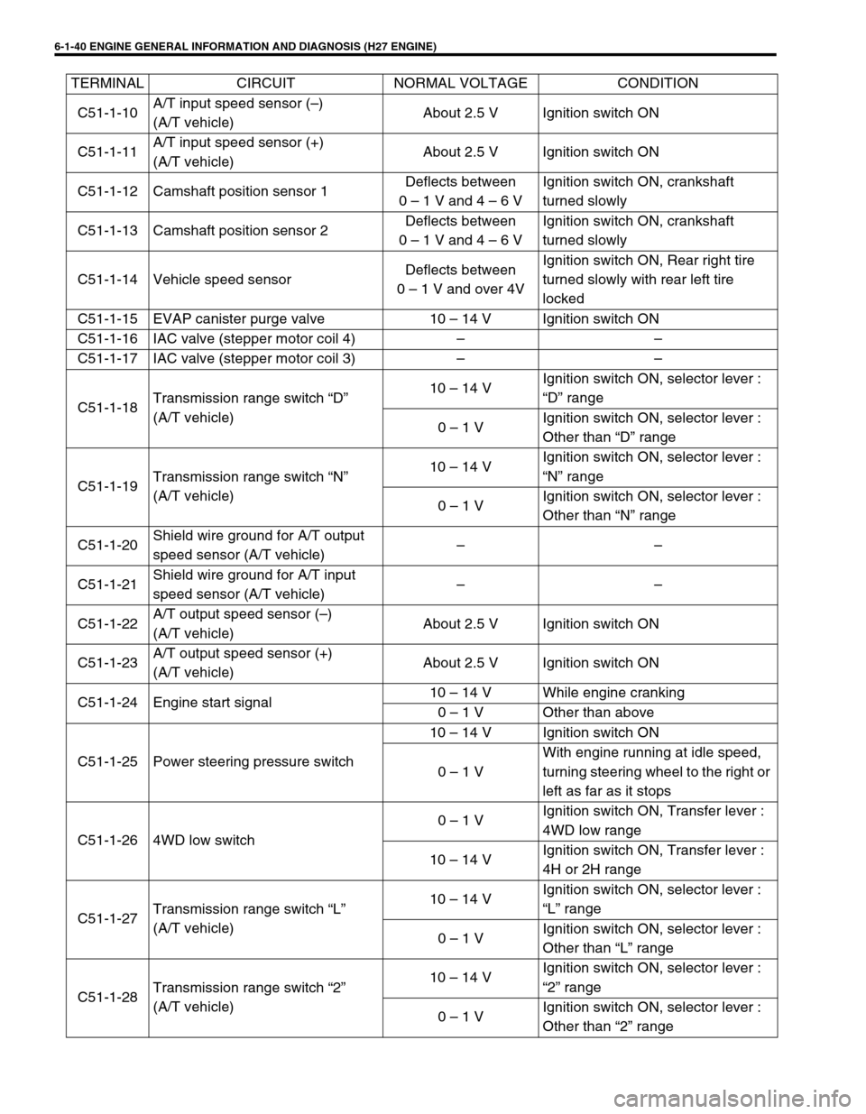
6-1-40 ENGINE GENERAL INFORMATION AND DIAGNOSIS (H27 ENGINE)
C51-1-10A/T input speed sensor (–)
(A/T vehicle)About 2.5 V Ignition switch ON
C51-1-11A/T input speed sensor (+)
(A/T vehicle)About 2.5 V Ignition switch ON
C51-1-12 Camshaft position sensor 1Deflects between
0 – 1 V and 4 – 6 VIgnition switch ON, crankshaft
turned slowly
C51-1-13 Camshaft position sensor 2Deflects between
0 – 1 V and 4 – 6 VIgnition switch ON, crankshaft
turned slowly
C51-1-14 Vehicle speed sensorDeflects between
0 – 1 V and over 4VIgnition switch ON, Rear right tire
turned slowly with rear left tire
locked
C51-1-15 EVAP canister purge valve 10 – 14 V Ignition switch ON
C51-1-16 IAC valve (stepper motor coil 4) – –
C51-1-17 IAC valve (stepper motor coil 3) – –
C51-1-18Transmission range switch “D”
(A/T vehicle)10 – 14 VIgnition switch ON, selector lever :
“D” range
0 – 1 VIgnition switch ON, selector lever :
Other than “D” range
C51-1-19Transmission range switch “N”
(A/T vehicle)10 – 14 VIgnition switch ON, selector lever :
“N” range
0 – 1 VIgnition switch ON, selector lever :
Other than “N” range
C51-1-20Shield wire ground for A/T output
speed sensor (A/T vehicle)––
C51-1-21Shield wire ground for A/T input
speed sensor (A/T vehicle)––
C51-1-22A/T output speed sensor (–)
(A/T vehicle)About 2.5 V Ignition switch ON
C51-1-23A/T output speed sensor (+)
(A/T vehicle)About 2.5 V Ignition switch ON
C51-1-24 Engine start signal10 – 14 V While engine cranking
0 – 1 V Other than above
C51-1-25 Power steering pressure switch10 – 14 V Ignition switch ON
0 – 1 VWith engine running at idle speed,
turning steering wheel to the right or
left as far as it stops
C51-1-26 4WD low switch0 – 1 VIgnition switch ON, Transfer lever :
4WD low range
10 – 14 VIgnition switch ON, Transfer lever :
4H or 2H range
C51-1-27Transmission range switch “L”
(A/T vehicle)10 – 14 VIgnition switch ON, selector lever :
“L” range
0 – 1 VIgnition switch ON, selector lever :
Other than “L” range
C51-1-28Transmission range switch “2”
(A/T vehicle)10 – 14 VIgnition switch ON, selector lever :
“2” range
0 – 1 VIgnition switch ON, selector lever :
Other than “2” range TERMINAL CIRCUIT NORMAL VOLTAGE CONDITION