body SUZUKI GRAND VITARA 2001 2.G Owner's Manual
[x] Cancel search | Manufacturer: SUZUKI, Model Year: 2001, Model line: GRAND VITARA, Model: SUZUKI GRAND VITARA 2001 2.GPages: 656, PDF Size: 14.31 MB
Page 169 of 656
6-1-8 ENGINE GENERAL INFORMATION AND DIAGNOSIS (H27 ENGINE)
Priority of Freeze Frame Data
ECM (PCM) has 4 frames where the freeze frame data can be stored. The first frame stores the freeze frame
data of the malfunction which was detected first. However, the freeze frame data stored in this frame is updated
according to the priority described below. (If malfunction as described in the upper square “1” below is detected
while the freeze frame data in the lower square “2” has been stored, the freeze frame data “2” will be updated by
the freeze frame data “1”.)
In the 2nd through the 4th frames, the freeze frame data of each malfunction is stored in the order as the mal-
function is detected. These data are not updated regardless of the priority.
Shown in the table below are examples of how freeze frame data are stored when two or more malfunctions are
detected.
Freeze Frame Data Clearance
The freeze frame data is cleared at the same time as clearance of DTC.
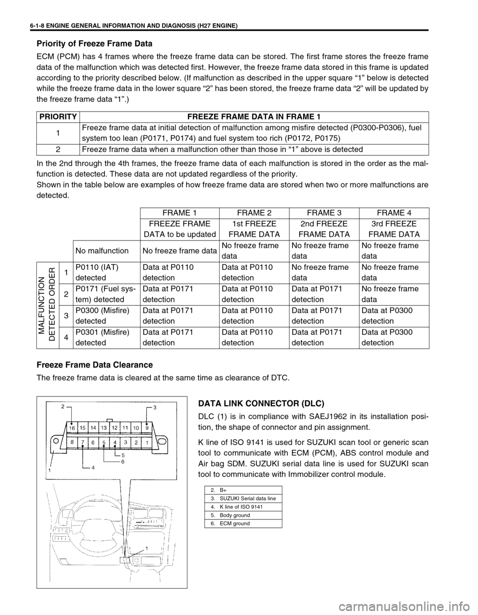
DATA LINK CONNECTOR (DLC)
DLC (1) is in compliance with SAEJ1962 in its installation posi-
tion, the shape of connector and pin assignment.
K line of ISO 9141 is used for SUZUKI scan tool or generic scan
tool to communicate with ECM (PCM), ABS control module and
Air bag SDM. SUZUKI serial data line is used for SUZUKI scan
tool to communicate with Immobilizer control module. PRIORITY FREEZE FRAME DATA IN FRAME 1
1Freeze frame data at initial detection of malfunction among misfire detected (P0300-P0306), fuel
system too lean (P0171, P0174) and fuel system too rich (P0172, P0175)
2 Freeze frame data when a malfunction other than those in “1” above is detected
FRAME 1 FRAME 2 FRAME 3 FRAME 4
FREEZE FRAME
DATA to be updated1st FREEZE
FRAME DATA2nd FREEZE
FRAME DATA3rd FREEZE
FRAME DATA
No malfunction No freeze frame dataNo freeze frame
dataNo freeze frame
dataNo freeze frame
data
MALFUNCTION
DETECTED ORDER
1P0110 (IAT)
detectedData at P0110
detectionData at P0110
detectionNo freeze frame
dataNo freeze frame
data
2P0171 (Fuel sys-
tem) detectedData at P0171
detectionData at P0110
detectionData at P0171
detectionNo freeze frame
data
3P0300 (Misfire)
detectedData at P0171
detectionData at P0110
detectionData at P0171
detectionData at P0300
detection
4P0301 (Misfire)
detectedData at P0171
detectionData at P0110
detectionData at P0171
detectionData at P0300
detection
2. B+
3. SUZUKI Serial data line
4. K line of ISO 9141
5. Body ground
6. ECM ground
Page 171 of 656
6-1-10 ENGINE GENERAL INFORMATION AND DIAGNOSIS (H27 ENGINE)
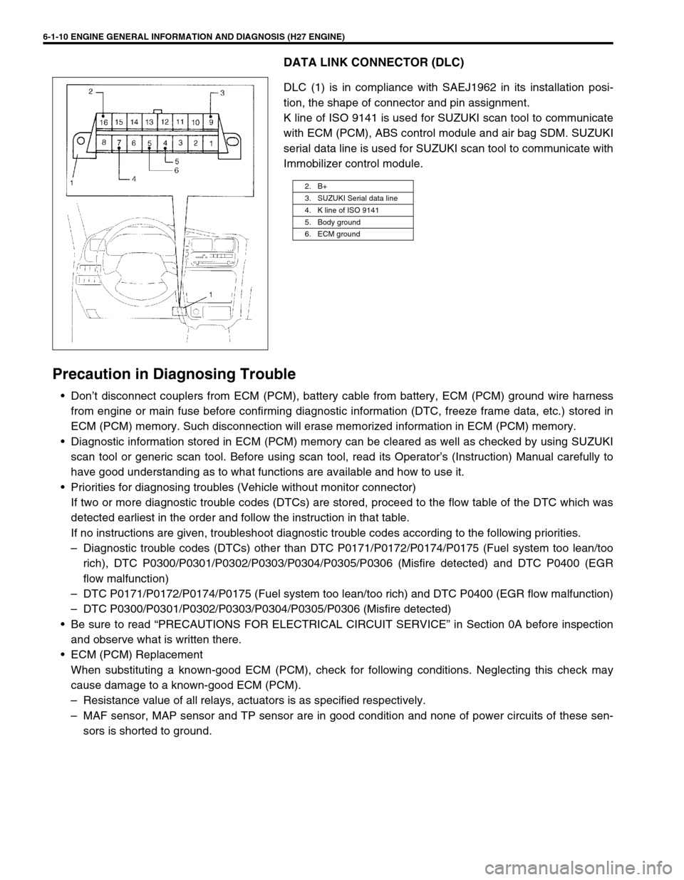
DATA LINK CONNECTOR (DLC)
DLC (1) is in compliance with SAEJ1962 in its installation posi-
tion, the shape of connector and pin assignment.
K line of ISO 9141 is used for SUZUKI scan tool to communicate
with ECM (PCM), ABS control module and air bag SDM. SUZUKI
serial data line is used for SUZUKI scan tool to communicate with
Immobilizer control module.
Precaution in Diagnosing Trouble
• Don’t disconnect couplers from ECM (PCM), battery cable from battery, ECM (PCM) ground wire harness
from engine or main fuse before confirming diagnostic information (DTC, freeze frame data, etc.) stored in
ECM (PCM) memory. Such disconnection will erase memorized information in ECM (PCM) memory.
• Diagnostic information stored in ECM (PCM) memory can be cleared as well as checked by using SUZUKI
scan tool or generic scan tool. Before using scan tool, read its Operator’s (Instruction) Manual carefully to
have good understanding as to what functions are available and how to use it.
• Priorities for diagnosing troubles (Vehicle without monitor connector)
If two or more diagnostic trouble codes (DTCs) are stored, proceed to the flow table of the DTC which was
detected earliest in the order and follow the instruction in that table.
If no instructions are given, troubleshoot diagnostic trouble codes according to the following priorities.
– Diagnostic trouble codes (DTCs) other than DTC P0171/P0172/P0174/P0175 (Fuel system too lean/too
rich), DTC P0300/P0301/P0302/P0303/P0304/P0305/P0306 (Misfire detected) and DTC P0400 (EGR
flow malfunction)
– DTC P0171/P0172/P0174/P0175 (Fuel system too lean/too rich) and DTC P0400 (EGR flow malfunction)
– DTC P0300/P0301/P0302/P0303/P0304/P0305/P0306 (Misfire detected)
• Be sure to read “PRECAUTIONS FOR ELECTRICAL CIRCUIT SERVICE” in Section 0A before inspection
and observe what is written there.
• ECM (PCM) Replacement
When substituting a known-good ECM (PCM), check for following conditions. Neglecting this check may
cause damage to a known-good ECM (PCM).
– Resistance value of all relays, actuators is as specified respectively.
– MAF sensor, MAP sensor and TP sensor are in good condition and none of power circuits of these sen-
sors is shorted to ground.
2. B+
3. SUZUKI Serial data line
4. K line of ISO 9141
5. Body ground
6. ECM ground
Page 203 of 656
6-1-42 ENGINE GENERAL INFORMATION AND DIAGNOSIS (H27 ENGINE)
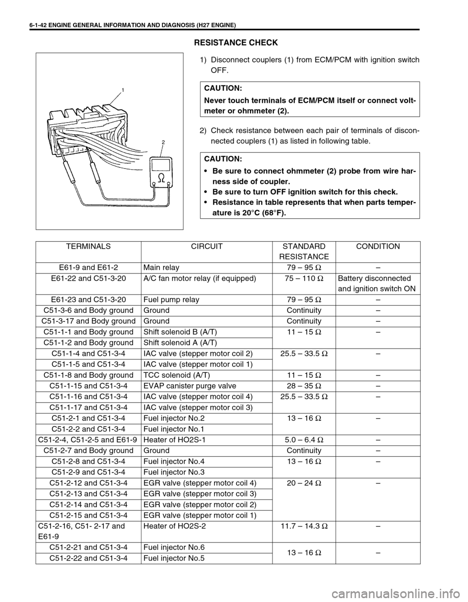
RESISTANCE CHECK
1) Disconnect couplers (1) from ECM/PCM with ignition switch
OFF.
2) Check resistance between each pair of terminals of discon-
nected couplers (1) as listed in following table. CAUTION:
Never touch terminals of ECM/PCM itself or connect volt-
meter or ohmmeter (2).
CAUTION:
Be sure to connect ohmmeter (2) probe from wire har-
ness side of coupler.
Be sure to turn OFF ignition switch for this check.
Resistance in table represents that when parts temper-
ature is 20°C (68°F).
TERMINALS CIRCUIT STANDARD
RESISTANCECONDITION
E61-9 and E61-2 Main relay 79 – 95 Ω–
E61-22 and C51-3-20 A/C fan motor relay (if equipped) 75 – 110 ΩBattery disconnected
and ignition switch ON
E61-23 and C51-3-20 Fuel pump relay 79 – 95 Ω–
C51-3-6 and Body ground Ground Continuity –
C51-3-17 and Body ground Ground Continuity –
C51-1-1 and Body ground Shift solenoid B (A/T) 11 – 15 Ω–
C51-1-2 and Body ground Shift solenoid A (A/T)
C51-1-4 and C51-3-4 IAC valve (stepper motor coil 2) 25.5 – 33.5 Ω–
C51-1-5 and C51-3-4 IAC valve (stepper motor coil 1)
C51-1-8 and Body ground TCC solenoid (A/T) 11 – 15 Ω–
C51-1-15 and C51-3-4 EVAP canister purge valve 28 – 35 Ω–
C51-1-16 and C51-3-4 IAC valve (stepper motor coil 4) 25.5 – 33.5 Ω–
C51-1-17 and C51-3-4 IAC valve (stepper motor coil 3)
C51-2-1 and C51-3-4 Fuel injector No.2 13 – 16 Ω–
C51-2-2 and C51-3-4 Fuel injector No.1
C51-2-4, C51-2-5 and E61-9 Heater of HO2S-1 5.0 – 6.4 Ω–
C51-2-7 and Body ground Ground Continuity –
C51-2-8 and C51-3-4 Fuel injector No.4 13 – 16 Ω–
C51-2-9 and C51-3-4 Fuel injector No.3
C51-2-12 and C51-3-4 EGR valve (stepper motor coil 4) 20 – 24 Ω–
C51-2-13 and C51-3-4 EGR valve (stepper motor coil 3)
C51-2-14 and C51-3-4 EGR valve (stepper motor coil 2)
C51-2-15 and C51-3-4 EGR valve (stepper motor coil 1)
C51-2-16, C51- 2-17 and
E61-9Heater of HO2S-2 11.7 – 14.3 Ω–
C51-2-21 and C51-3-4 Fuel injector No.6
13 – 16 Ω–
C51-2-22 and C51-3-4 Fuel injector No.5
Page 216 of 656
ENGINE GENERAL INFORMATION AND DIAGNOSIS (H27 ENGINE) 6-1-55
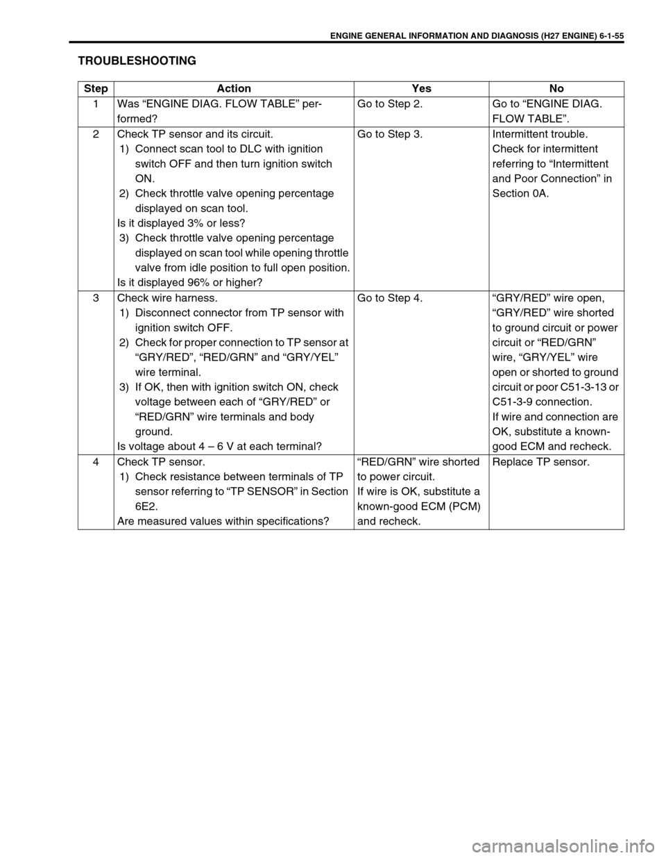
TROUBLESHOOTING
Step Action Yes No
1 Was “ENGINE DIAG. FLOW TABLE” per-
formed?Go to Step 2. Go to “ENGINE DIAG.
FLOW TABLE”.
2 Check TP sensor and its circuit.
1) Connect scan tool to DLC with ignition
switch OFF and then turn ignition switch
ON.
2) Check throttle valve opening percentage
displayed on scan tool.
Is it displayed 3% or less?
3) Check throttle valve opening percentage
displayed on scan tool while opening throttle
valve from idle position to full open position.
Is it displayed 96% or higher?Go to Step 3. Intermittent trouble.
Check for intermittent
referring to “Intermittent
and Poor Connection” in
Section 0A.
3 Check wire harness.
1) Disconnect connector from TP sensor with
ignition switch OFF.
2) Check for proper connection to TP sensor at
“GRY/RED”, “RED/GRN” and “GRY/YEL”
wire terminal.
3) If OK, then with ignition switch ON, check
voltage between each of “GRY/RED” or
“RED/GRN” wire terminals and body
ground.
Is voltage about 4 – 6 V at each terminal?Go to Step 4. “GRY/RED” wire open,
“GRY/RED” wire shorted
to ground circuit or power
circuit or “RED/GRN”
wire, “GRY/YEL” wire
open or shorted to ground
circuit or poor C51-3-13 or
C51-3-9 connection.
If wire and connection are
OK, substitute a known-
good ECM and recheck.
4 Check TP sensor.
1) Check resistance between terminals of TP
sensor referring to “TP SENSOR” in Section
6E2.
Are measured values within specifications?“RED/GRN” wire shorted
to power circuit.
If wire is OK, substitute a
known-good ECM (PCM)
and recheck.Replace TP sensor.
Page 244 of 656
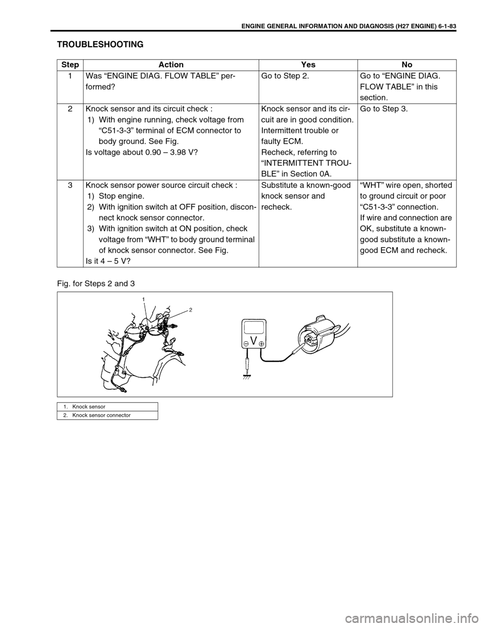
ENGINE GENERAL INFORMATION AND DIAGNOSIS (H27 ENGINE) 6-1-83
TROUBLESHOOTING
Fig. for Steps 2 and 3Step Action Yes No
1 Was “ENGINE DIAG. FLOW TABLE” per-
formed?Go to Step 2. Go to “ENGINE DIAG.
FLOW TABLE” in this
section.
2 Knock sensor and its circuit check :
1) With engine running, check voltage from
“C51-3-3” terminal of ECM connector to
body ground. See Fig.
Is voltage about 0.90 – 3.98 V?Knock sensor and its cir-
cuit are in good condition.
Intermittent trouble or
faulty ECM.
Recheck, referring to
“INTERMITTENT TROU-
BLE” in Section 0A.Go to Step 3.
3 Knock sensor power source circuit check :
1) Stop engine.
2) With ignition switch at OFF position, discon-
nect knock sensor connector.
3) With ignition switch at ON position, check
voltage from “WHT” to body ground terminal
of knock sensor connector. See Fig.
Is it 4 – 5 V?Substitute a known-good
knock sensor and
recheck.“WHT” wire open, shorted
to ground circuit or poor
“C51-3-3” connection.
If wire and connection are
OK, substitute a known-
good substitute a known-
good ECM and recheck.
1. Knock sensor
2. Knock sensor connector
Page 269 of 656
6-1-108 ENGINE GENERAL INFORMATION AND DIAGNOSIS (H27 ENGINE)
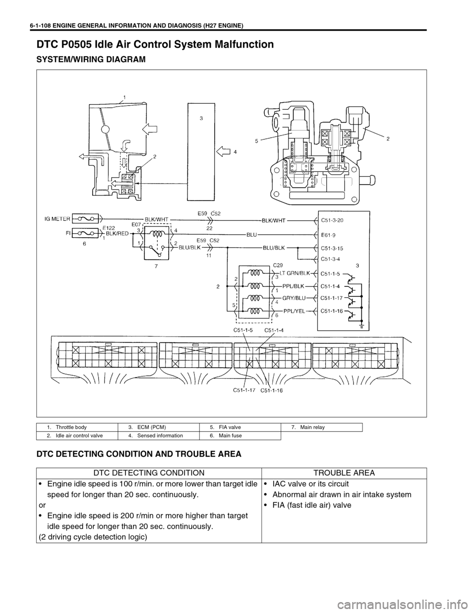
DTC P0505 Idle Air Control System Malfunction
SYSTEM/WIRING DIAGRAM
DTC DETECTING CONDITION AND TROUBLE AREA
1. Throttle body 3. ECM (PCM) 5. FIA valve 7. Main relay
2. Idle air control valve 4. Sensed information 6. Main fuse
DTC DETECTING CONDITION TROUBLE AREA
•Engine idle speed is 100 r/min. or more lower than target idle
speed for longer than 20 sec. continuously.
or
•Engine idle speed is 200 r/min or more higher than target
idle speed for longer than 20 sec. continuously.
(2 driving cycle detection logic)•IAC valve or its circuit
•Abnormal air drawn in air intake system
•FIA (fast idle air) valve
Page 271 of 656
6-1-110 ENGINE GENERAL INFORMATION AND DIAGNOSIS (H27 ENGINE)
DTC P0601 (DTC No.71) Internal Control Module Memory Check Sum Error
SYSTEM DESCRIPTION
Internal control module is installed in ECM (PCM).
DTC DETECTING CONDITION AND TROUBLE AREA
DTC CONFIRMATION PROCEDURE
1) Connect scan tool to DLC with ignition switch OFF.
2) Turn ON ignition switch and clear DTC, pending DTC and freeze frame data by using scan tool.
3) Start engine and run it at idle if possible.
4) Check DTC by using scan tool.
TROUBLESHOOTING
Substitute a known-good ECM (PCM) and recheck.6 Was idle speed higher than specification in
Step 2?Check FIA valve for mal-
function.
Check abnormal air inhal-
ing from intake manifold,
throttle body, PCV valve
and EVAP canister purge
control system.Check parts or system
which can cause engine
low idle.
Check FIA valve for stuck.
Air inhaling from between
throttle body and MAF
sensor, EGR valve mal-
function (leakage from
valve seat), accessory
engine load, clog of idle
air passage, engine
mechanical, engine over-
heat and etc. Step Action Yes No
DTC DETECTING CONDITION TROUBLE AREA
Data write error or check sum error ECM (PCM)
Page 282 of 656

ENGINE GENERAL INFORMATION AND DIAGNOSIS (H27 ENGINE) 6-1-121
Table B-4 Idle Air Control System Inspection
WIRING DIAGRAM
INSPECTION
1. Throttle body 3. ECM (PCM) 5. Main fuse
2. Idle air control valve 4. Sensed information 6. Main relay
Step Action Yes No
1 Check engine idle speed and IAC duty
referring to “IDLE SPEED/IAC DUTY
INSPECTION” in Section 6E2.
Is idle speed/IAC duty within specifica-
tion?Go to Step 2. Go to Step 3.
2 Is engine idle speed kept specified speed
even with headlights turned ON?System is in good condition. Go to Step 3.
Page 283 of 656
6-1-122 ENGINE GENERAL INFORMATION AND DIAGNOSIS (H27 ENGINE)
3 Check IAC valve referring to “IAC VALVE
INSPECTION” in Section 6E2.
Is check result as specified?Go to Step 4. IAC valve malfunction, “BLU/
BLK”, “LT GRN/BLK”, “PPL/
BLK”, “GRY/BLU” or “PPL/
YEL” wire open or short or
poor coupler connection.
If all above are OK, substi-
tute a known-good ECM
(PCM) and recheck.
4 Was idle speed within specification in
Step 1?Check for following :
FIA valve, Vacuum leaks, air inhal-
ing, EVAP canister purge control
system, accessory engine load,
stuck of PCV valve, clog of idle air
passage, MAF sensor, TP sensor,
ECT sensor, EGR valve malfunc-
tion (leakage from valve seat), A/C
signal, transmission range switch
signal and power steering switch
signal.Go to Step 5.
5 Was idle speed higher than specification
in Step 1?Go to Step 6. Go to Step 8.
6 Check A/C (input) signal circuit referring
to Step 1 of “Table B-5”. (A/C signal can
be also checked by using SUZUKI scan
tool.)
Is it in good condition?Go to Step 7. A/C signal circuit open or
short, or A/C system mal-
function.
7 Was IAC duty less than about 2% in Step
1 of this table?
Check FIA valve.
Check abnormal air inhaling from
intake manifold, throttle body, PCV
valve and EVAP canister purge
control system.Check TP sensor (closed
throttle position) and ECT
sensor for performance.
If sensors are OK, substitute
a known-good ECM (PCM)
and recheck.
8 Check transmission range switch signal
referring to “INSPECTION OF ECM
(PCM) AND ITS CIRCUIT” in this section.
Is check result satisfactory?Go to Step 9. Transmission range switch
malfunction or its circuits
open or short.
9 Was IAC duty more than about 30% in
Step 1 of this table?Check parts or system which can
cause engine low idle.
Check FIA valve.
Air inhaling from between throttle
body and MAF sensor, EGR valve
malfunction (leakage from valve
seat), accessory engine load, clog
of idle air passage and etc.Substitute a known-good
ECM (PCM) and recheck. Step Action Yes No
Page 286 of 656
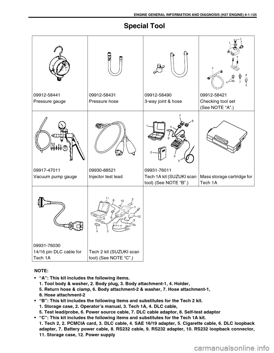
ENGINE GENERAL INFORMATION AND DIAGNOSIS (H27 ENGINE) 6-1-125
Special Tool
09912-58441 09912-58431 09912-58490 09912-58421
Pressure gauge Pressure hose 3-way joint & hose Checking tool set
(See NOTE “A”.)
09917-47011 09930-88521 09931-76011
Vacuum pump gauge Injector test lead Tech 1A kit (SUZUKI scan
tool) (See NOTE “B”.)Mass storage cartridge for
Tech 1A
09931-76030
14/16 pin DLC cable for
Tech 1ATech 2 kit (SUZUKI scan
tool) (See NOTE “C”.)
NOTE:
“A”: This kit includes the following items.
1. Tool body & washer, 2. Body plug, 3. Body attachment-1, 4. Holder,
5. Return hose & clamp, 6. Body attachment-2 & washer, 7. Hose attachment-1,
8. Hose attachment-2
“B”: This kit includes the following items and substitutes for the Tech 2 kit.
1. Storage case, 2. Operator’s manual, 3. Tech 1A, 4. DLC cable,
5. Test lead/probe, 6. Power source cable, 7. DLC cable adaptor, 8. Self-test adaptor
“C”: This kit includes the following items and substitutes for the Tech 1A kit.
1. Tech 2, 2. PCMCIA card, 3. DLC cable, 4. SAE 16/19 adapter, 5. Cigarette cable, 6. DLC loopback
adapter, 7. Battery power cable, 8. RS232 cable, 9. RS232 adapter, 10. RS232 loopback connector,
11. Storage case, 12. Power supply