body SUZUKI GRAND VITARA 2001 2.G Service Manual
[x] Cancel search | Manufacturer: SUZUKI, Model Year: 2001, Model line: GRAND VITARA, Model: SUZUKI GRAND VITARA 2001 2.GPages: 656, PDF Size: 14.31 MB
Page 339 of 656

6E2-6 ENGINE AND EMISSION CONTROL SYSTEM (SEQUENTIAL MULTIPORT FUEL INJECTION FOR H27 ENGINE)
Air Intake System
The main components of the air intake system are air cleaner, mass air flow sensor, air cleaner, intake air pipe,
throttle body, intake collector, idle air control valve and intake manifold.
The air (by the amount corresponding to the throttle valve opening and engine speed) is filtered by the air
cleaner, passes through the throttle body, is distributed by the intake manifold and finally drawn into each com-
bustion chamber.
When the idle air control valve is opened according to the signal from ECM (PCM), the air bypasses the throttle
valve through bypass passage and is finally drawn into the intake manifold.
“A” : Air 1. Air cleaner 6. PCV hose 11. Breather hose 16. IAC valve and fast idle control system
“B” : EGR 2. IAT sensor 7. Brake booster 12. MAF sensor 17. FIA valve
“C” : Engine coolant 3. Resonator 8. Fuel pressure
regulator hose13. EGR valve 18. Thermo - WAX
4. Intake manifold 9. Intake air pipe 14. TP sensor
5. Intake collector 10. Throttle body 15. IAC valve
18
10
17
15
16
Page 347 of 656
6E2-14 ENGINE AND EMISSION CONTROL SYSTEM (SEQUENTIAL MULTIPORT FUEL INJECTION FOR H27 ENGINE)
Accelerator Cable Adjustment
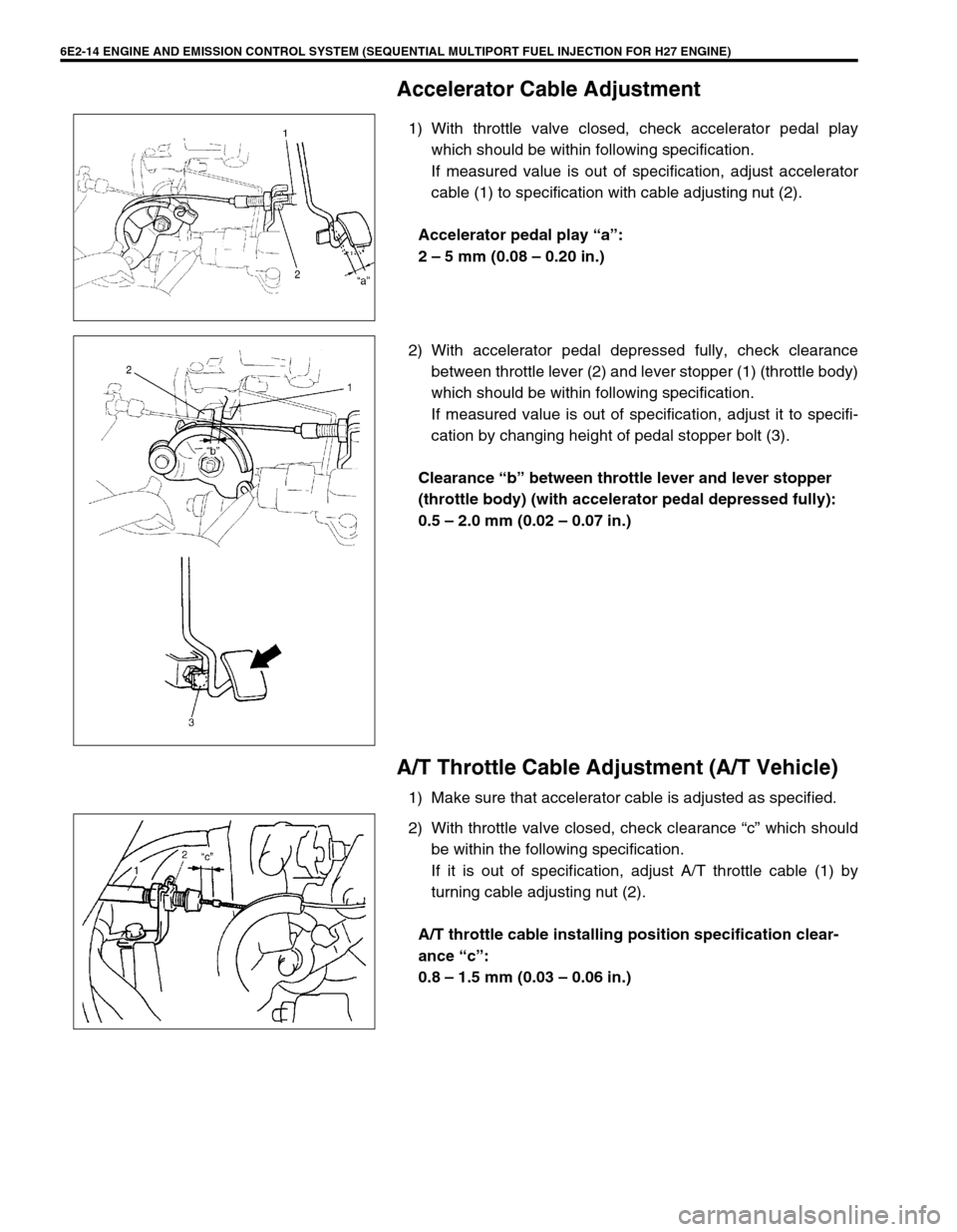
1) With throttle valve closed, check accelerator pedal play
which should be within following specification.
If measured value is out of specification, adjust accelerator
cable (1) to specification with cable adjusting nut (2).
Accelerator pedal play “a”:
2 – 5 mm (0.08 – 0.20 in.)
2) With accelerator pedal depressed fully, check clearance
between throttle lever (2) and lever stopper (1) (throttle body)
which should be within following specification.
If measured value is out of specification, adjust it to specifi-
cation by changing height of pedal stopper bolt (3).
Clearance “b” between throttle lever and lever stopper
(throttle body) (with accelerator pedal depressed fully):
0.5 – 2.0 mm (0.02 – 0.07 in.)
A/T Throttle Cable Adjustment (A/T Vehicle)
1) Make sure that accelerator cable is adjusted as specified.
2) With throttle valve closed, check clearance “c” which should
be within the following specification.
If it is out of specification, adjust A/T throttle cable (1) by
turning cable adjusting nut (2).
A/T throttle cable installing position specification clear-
ance “c”:
0.8 – 1.5 mm (0.03 – 0.06 in.)
Page 351 of 656
6E2-18 ENGINE AND EMISSION CONTROL SYSTEM (SEQUENTIAL MULTIPORT FUEL INJECTION FOR H27 ENGINE)
Air Intake System
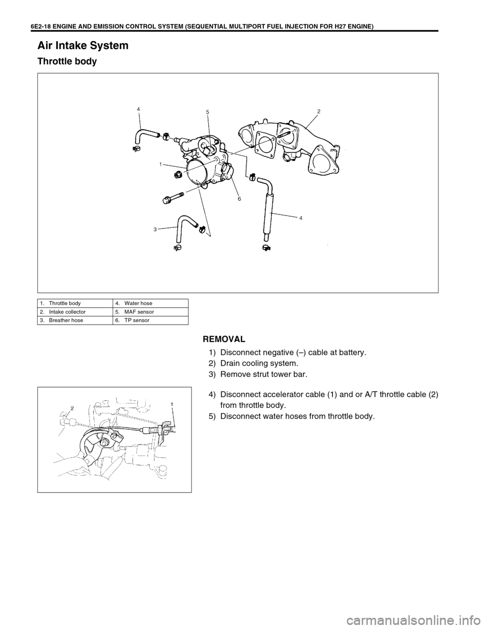
Throttle body
REMOVAL
1) Disconnect negative (–) cable at battery.
2) Drain cooling system.
3) Remove strut tower bar.
4) Disconnect accelerator cable (1) and or A/T throttle cable (2)
from throttle body.
5) Disconnect water hoses from throttle body.
1. Throttle body 4. Water hose
2. Intake collector 5. MAF sensor
3. Breather hose 6. TP sensor
Page 352 of 656
ENGINE AND EMISSION CONTROL SYSTEM (SEQUENTIAL MULTIPORT FUEL INJECTION FOR H27 ENGINE) 6E2-19
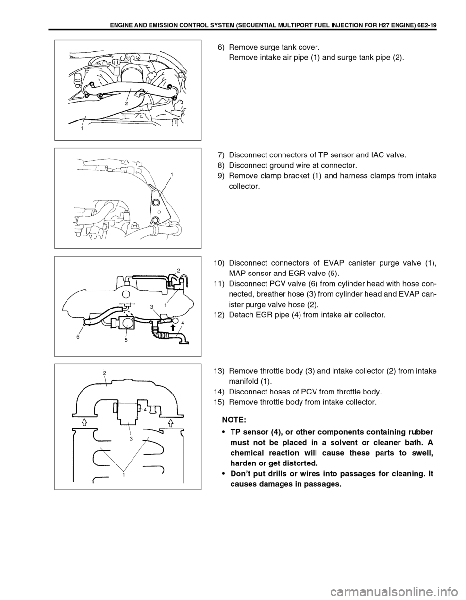
6) Remove surge tank cover.
Remove intake air pipe (1) and surge tank pipe (2).
7) Disconnect connectors of TP sensor and IAC valve.
8) Disconnect ground wire at connector.
9) Remove clamp bracket (1) and harness clamps from intake
collector.
10) Disconnect connectors of EVAP canister purge valve (1),
MAP sensor and EGR valve (5).
11) Disconnect PCV valve (6) from cylinder head with hose con-
nected, breather hose (3) from cylinder head and EVAP can-
ister purge valve hose (2).
12) Detach EGR pipe (4) from intake air collector.
13) Remove throttle body (3) and intake collector (2) from intake
manifold (1).
14) Disconnect hoses of PCV from throttle body.
15) Remove throttle body from intake collector.
NOTE:
TP sensor (4), or other components containing rubber
must not be placed in a solvent or cleaner bath. A
chemical reaction will cause these parts to swell,
harden or get distorted.
Don’t put drills or wires into passages for cleaning. It
causes damages in passages.
Page 353 of 656
6E2-20 ENGINE AND EMISSION CONTROL SYSTEM (SEQUENTIAL MULTIPORT FUEL INJECTION FOR H27 ENGINE)
CLEANING
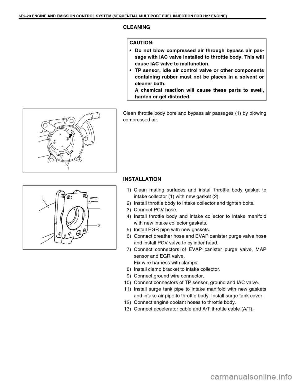
Clean throttle body bore and bypass air passages (1) by blowing
compressed air.
INSTALLATION
1) Clean mating surfaces and install throttle body gasket to
intake collector (1) with new gasket (2).
2) Install throttle body to intake collector and tighten bolts.
3) Connect PCV hose.
4) Install throttle body and intake collector to intake manifold
with new intake collector gaskets.
5) Install EGR pipe with new gaskets.
6) Connect breather hose and EVAP canister purge valve hose
and install PCV valve to cylinder head.
7) Connect connectors of EVAP canister purge valve, MAP
sensor and EGR valve.
Fix wire harness with clamps.
8) Install clamp bracket to intake collector.
9) Connect ground wire connector.
10) Connect connectors of TP sensor, ground and IAC valve.
11) Install surge tank pipe to intake manifold with new gaskets
and intake air pipe to throttle body. Install surge tank cover.
12) Connect engine coolant hoses to throttle body.
13) Connect accelerator cable and A/T throttle cable (A/T).CAUTION:
Do not blow compressed air through bypass air pas-
sage with IAC valve installed to throttle body. This will
cause IAC valve to malfunction.
TP sensor, idle air control valve or other components
containing rubber must not be places in a solvent or
cleaner bath.
A chemical reaction will cause these parts to swell,
harden or get distorted.
Page 354 of 656
ENGINE AND EMISSION CONTROL SYSTEM (SEQUENTIAL MULTIPORT FUEL INJECTION FOR H27 ENGINE) 6E2-21
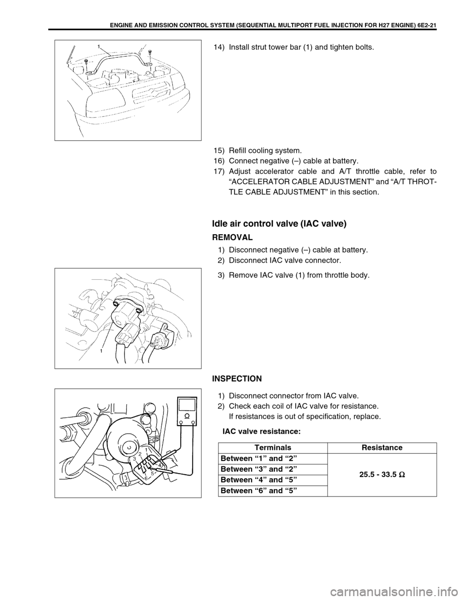
14) Install strut tower bar (1) and tighten bolts.
15) Refill cooling system.
16) Connect negative (–) cable at battery.
17) Adjust accelerator cable and A/T throttle cable, refer to
“ACCELERATOR CABLE ADJUSTMENT” and “A/T THROT-
TLE CABLE ADJUSTMENT” in this section.
Idle air control valve (IAC valve)
REMOVAL
1) Disconnect negative (–) cable at battery.
2) Disconnect IAC valve connector.
3) Remove IAC valve (1) from throttle body.
INSPECTION
1) Disconnect connector from IAC valve.
2) Check each coil of IAC valve for resistance.
If resistances is out of specification, replace.
IAC valve resistance:
Terminals Resistance
Between “1” and “2”
25.5 - 33.5 Ω
ΩΩ Ω Between “3” and “2”
Between “4” and “5”
Between “6” and “5”
Page 355 of 656
6E2-22 ENGINE AND EMISSION CONTROL SYSTEM (SEQUENTIAL MULTIPORT FUEL INJECTION FOR H27 ENGINE)
3) Remove air cleaner outlet hose and remove IAC valve from
throttle body.
4) Connect connector to IAC valve.
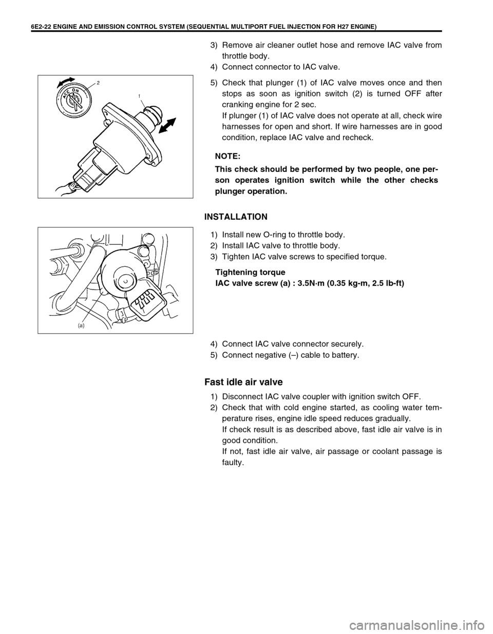
5) Check that plunger (1) of IAC valve moves once and then
stops as soon as ignition switch (2) is turned OFF after
cranking engine for 2 sec.
If plunger (1) of IAC valve does not operate at all, check wire
harnesses for open and short. If wire harnesses are in good
condition, replace IAC valve and recheck.
INSTALLATION
1) Install new O-ring to throttle body.
2) Install IAC valve to throttle body.
3) Tighten IAC valve screws to specified torque.
Tightening torque
IAC valve screw (a) : 3.5N·m (0.35 kg-m, 2.5 lb-ft)
4) Connect IAC valve connector securely.
5) Connect negative (–) cable to battery.
Fast idle air valve
1) Disconnect IAC valve coupler with ignition switch OFF.
2) Check that with cold engine started, as cooling water tem-
perature rises, engine idle speed reduces gradually.
If check result is as described above, fast idle air valve is in
good condition.
If not, fast idle air valve, air passage or coolant passage is
faulty. NOTE:
This check should be performed by two people, one per-
son operates ignition switch while the other checks
plunger operation.
Page 358 of 656

ENGINE AND EMISSION CONTROL SYSTEM (SEQUENTIAL MULTIPORT FUEL INJECTION FOR H27 ENGINE) 6E2-25
REMOVAL
Remove fuel tank from body according to procedure described in
Section 6C and remove fuel pump from fuel tank.
INSPECTION
Check fuel pump filter for evidence of dirt and contamination. If
present, clean and check for presence of dirt in fuel tank.
INSTALLATION
Install fuel pump to fuel tank and then install fuel tank to body
according to procedure described in “Section 6C”.
Fuel pressure regulator
REMOVAL
1) Relieve fuel pressure in fuel feed line referring to “FUEL
PRESSURE RELIEF PROCEDURE” in Section 6-1.
2) Disconnect negative (–) cable from battery.
3) Disconnect vacuum hose (1) from fuel pressure regulator.
4) Remove fuel pressure regulator (1) from fuel delivery pipe
(3).
5) Disconnect fuel return hose (2) from fuel pressure regulator.
CAUTION:
A small amount of fuel may be released when it is from
delivery pipe.
Place a shop cloth under delivery pipe so that released
fuel is absorbed in it.
CAUTION:
A small amount of fuel may be released when hose is dis-
connected. Cover hose to be disconnected with a shop
cloth.
Page 360 of 656

ENGINE AND EMISSION CONTROL SYSTEM (SEQUENTIAL MULTIPORT FUEL INJECTION FOR H27 ENGINE) 6E2-27
REMOVAL
1) Relieve fuel pressure in fuel feed line referring to “FUEL
PRESSURE RELIEF PROCEDURE” in Section 6-1.
2) Remove throttle body intake collector, refer to “THROTTLE
BODY” in this section.
3) Disconnect fuel feed hose (1) and fuel return hose (2).
4) Disconnect vacuum hose (4) and fuel return hose from fuel
pressure regulator (5).
5) Remove fuel feed pipe (8) and fuel connect pipe (7) from
delivery pipes (6) (right and left).
6) Disconnect connector (3) from each injector.
7) Remove delivery pipes (1) (right and left) from intake mani-
fold.
8) Remove fuel injector(s).
INSPECTION
CAUTION:
A small amount of fuel may be released when it is from
delivery pipe.
Place a shop cloth under delivery pipe so that released
fuel is absorbed in it.
WARNING:
As fuel is injected in this inspection, perform in a well
ventilated area and away from open flames.
Use special care to prevent sparking when connecting
and disconnecting test lead to and from battery.
Page 363 of 656

6E2-30 ENGINE AND EMISSION CONTROL SYSTEM (SEQUENTIAL MULTIPORT FUEL INJECTION FOR H27 ENGINE)
5) Install fuel connect pipe (1) and tighten union bolts to speci-
fied torque with new gaskets (3).
Tightening torque
Fuel connect pipe union bolt
(b) : 30 N·m (3.0 kg-m, 22.0 lb-ft)
6) Install fuel feed pipe (2) and tighten union bolt to specified
torque with new gaskets.
Tightening torque
Fuel feed pipe union bolt
(a) : 30 N·m (3.0 kg-m, 22.0 lb-ft)
7) Connect vacuum hose (5) and fuel return hose (4) to fuel
pressure regulator.
8) Connect fuel feed hose (1) and fuel return hose (2).
9) Connect connectors of injector wire (3) to injectors.
10) Install throttle body and intake collector, refer to “THROTTLE
BODY” in this section.
11) With engine “OFF” and ignition switch “ON”, check for fuel
leaks around fuel line connection.