low oil pressure SUZUKI GRAND VITARA 2001 2.G Owner's Manual
[x] Cancel search | Manufacturer: SUZUKI, Model Year: 2001, Model line: GRAND VITARA, Model: SUZUKI GRAND VITARA 2001 2.GPages: 656, PDF Size: 14.31 MB
Page 338 of 656
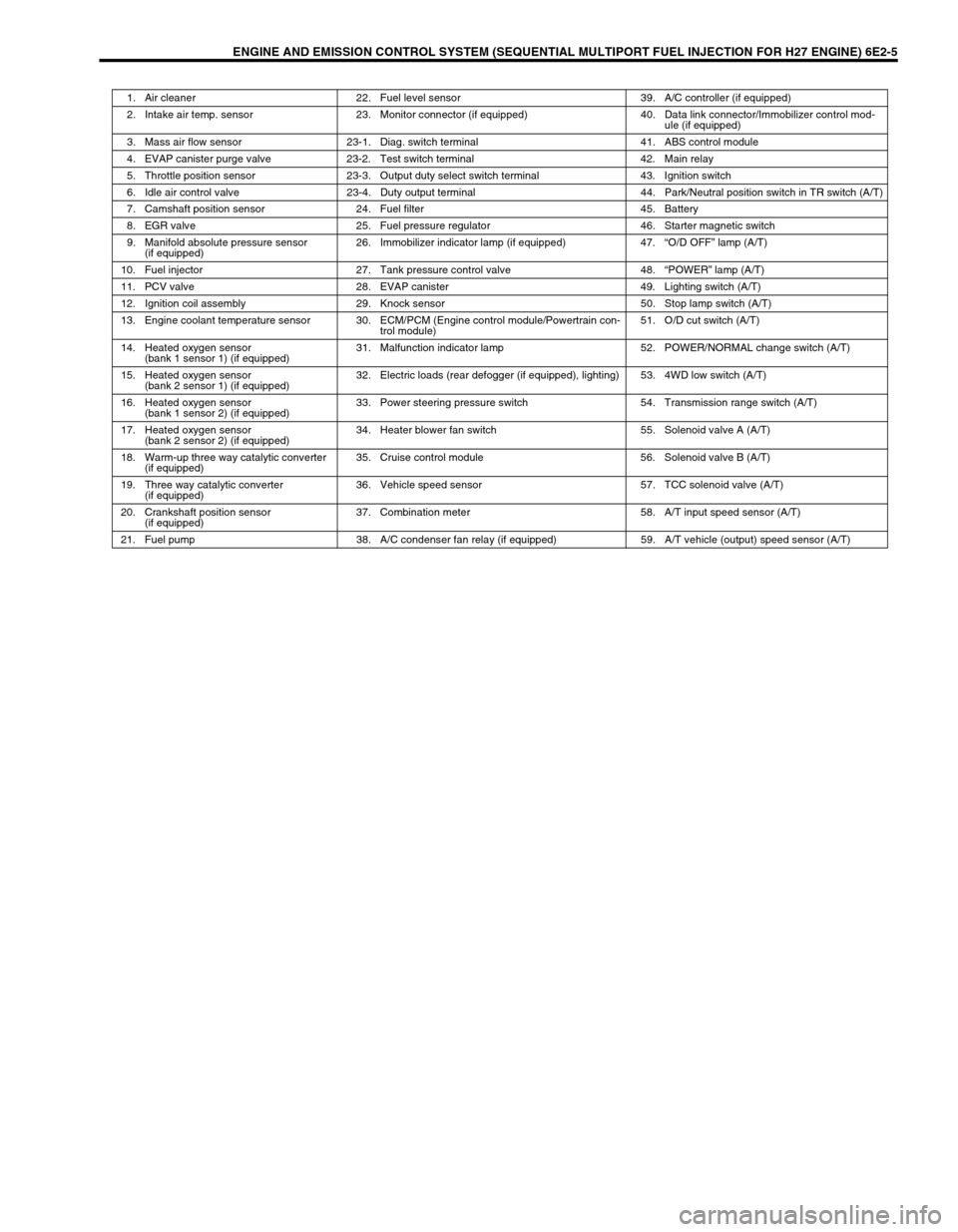
ENGINE AND EMISSION CONTROL SYSTEM (SEQUENTIAL MULTIPORT FUEL INJECTION FOR H27 ENGINE) 6E2-5
1. Air cleaner 22. Fuel level sensor 39. A/C controller (if equipped)
2. Intake air temp. sensor 23. Monitor connector (if equipped) 40. Data link connector/Immobilizer control mod-
ule (if equipped)
3. Mass air flow sensor 23-1. Diag. switch terminal 41. ABS control module
4. EVAP canister purge valve 23-2. Test switch terminal 42. Main relay
5. Throttle position sensor 23-3. Output duty select switch terminal 43. Ignition switch
6. Idle air control valve 23-4. Duty output terminal 44. Park/Neutral position switch in TR switch (A/T)
7. Camshaft position sensor 24. Fuel filter 45. Battery
8. EGR valve 25. Fuel pressure regulator 46. Starter magnetic switch
9. Manifold absolute pressure sensor
(if equipped)26. Immobilizer indicator lamp (if equipped) 47.“O/D OFF” lamp (A/T)
10. Fuel injector 27. Tank pressure control valve 48.“POWER” lamp (A/T)
11. PCV valve 28. EVAP canister 49. Lighting switch (A/T)
12. Ignition coil assembly 29. Knock sensor 50. Stop lamp switch (A/T)
13. Engine coolant temperature sensor 30. ECM/PCM (Engine control module/Powertrain con-
trol module)51. O/D cut switch (A/T)
14. Heated oxygen sensor
(bank 1 sensor 1) (if equipped)31. Malfunction indicator lamp 52. POWER/NORMAL change switch (A/T)
15. Heated oxygen sensor
(bank 2 sensor 1) (if equipped)32. Electric loads (rear defogger (if equipped), lighting) 53. 4WD low switch (A/T)
16. Heated oxygen sensor
(bank 1 sensor 2) (if equipped)33. Power steering pressure switch 54. Transmission range switch (A/T)
17. Heated oxygen sensor
(bank 2 sensor 2) (if equipped)34. Heater blower fan switch 55. Solenoid valve A (A/T)
18. Warm-up three way catalytic converter
(if equipped)35. Cruise control module 56. Solenoid valve B (A/T)
19. Three way catalytic converter
(if equipped)36. Vehicle speed sensor 57. TCC solenoid valve (A/T)
20. Crankshaft position sensor
(if equipped)37. Combination meter 58. A/T input speed sensor (A/T)
21. Fuel pump 38. A/C condenser fan relay (if equipped) 59. A/T vehicle (output) speed sensor (A/T)
Page 341 of 656
6E2-8 ENGINE AND EMISSION CONTROL SYSTEM (SEQUENTIAL MULTIPORT FUEL INJECTION FOR H27 ENGINE)
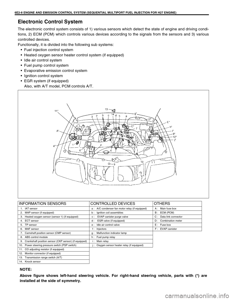
Electronic Control System
The electronic control system consists of 1) various sensors which detect the state of engine and driving condi-
tions, 2) ECM (PCM) which controls various devices according to the signals from the sensors and 3) various
controlled devices.
Functionally, it is divided into the following sub systems:
•Fuel injection control system
•Heated oxygen sensor heater control system (if equipped)
•Idle air control system
•Fuel pump control system
•Evaporative emission control system
•Ignition control system
•EGR system (if equipped)
Also, with A/T model, PCM controls A/T.
INFORMATION SENSORS CONTROLLED DEVICES OTHERS
1. IAT sensor a : A/C condenser fan motor relay (if equipped) A : Main fuse box
2. MAP sensor (if equipped) b : Ignition coil assemblies B : ECM (PCM)
3. Heated oxygen sensor (sensor 1) (if equipped) c : EVAP canister purge valve C : Data link connector
4. ECT sensor d : EGR valve (if equipped) D : Combination meter
5. TP sensor e : Idle air control valve E : Fuse box
6. MAF sensor f : Injectors F : EVAP canister
7. Camshaft position sensor (CMP sensor) g : Malfunction indicator lamp
8. ABS control module h : Fuel pump relay
9. Crankshaft position sensor (CKP sensor) (if equipped) i : Main relay
10. Power steering pressure switch (PSP switch) j : Oxygen sensor heater relay (if equipped)
11. CO adjusting resistor (if equipped)
12. Monitor connector (if equipped)
13. Transmission range switch (A/T)
14. Knock sensor
NOTE:
Above figure shows left-hand steering vehicle. For right-hand steering vehicle, parts with (*) are
installed at the side of symmetry.
Page 343 of 656
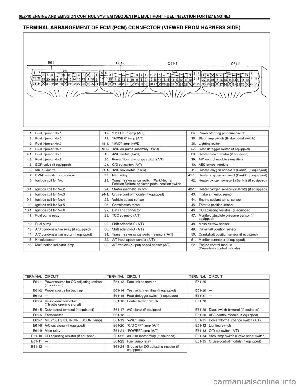
6E2-10 ENGINE AND EMISSION CONTROL SYSTEM (SEQUENTIAL MULTIPORT FUEL INJECTION FOR H27 ENGINE)
TERMINAL ARRANGEMENT OF ECM (PCM) CONNECTOR (VIEWED FROM HARNESS SIDE)
1. Fuel injector No.1 17.“O/D OFF” lamp (A/T) 34. Power steering pressure switch
2. Fuel injector No.2 18.“POWER” lamp (A/T) 35. Stop lamp switch (Brake pedal switch)
3. Fuel injector No.3 18-1.“4WD” lamp (4WD) 36. Lighting switch
4. Fuel injector No.4 18-2. 4WD air pump assembly (4WD) 37. Rear defogger switch (if equipped)
4-1. Fuel injector No.5 19. 4WD switch (4WD) 38. Heater blower motor (if equipped)
4-2. Fuel injector No.6 20. Power/Normal change switch (A/T) 39. A/C control module (amplifier)
5. EGR valve (if equipped) 21. O/D cut switch (A/T) 40. ABS control module
6. Idle air control 21-1. 4WD low switch (4WD) 41. Heated oxygen sensor-1 (Bank1) (if equipped)
7. EVAP canister purge valve 22. Main relay 41-1. Heated oxygen sensor-1 (Bank2) (if equipped)
8. Ignition coil for No.1 23. Transmission range switch (Park/Neutral
Position Switch) or clutch pedal position switch42. Heater oxygen sensor-2 (Bank1) (if equipped)
8-1. Ignition coil for No.2 24. Starter magnetic switch 42-1. Heater oxygen sensor-2 (Bank2) (if equipped)
9. Ignition coil for No.3 24-1. Cruise control module (if equipped) 43. Intake air temp. sensor
9-1. Ignition coil for No.4 25. Vehicle speed sensor 44. Engine coolant temp. sensor
10. Ignition coil for No.5 26. Combination meter 45. Throttle position sensor
10-1. Ignition coil for No.6 27. Data link connector 46. CO adjusting resistor (if equipped)
11. Fuel pump relay 28. TCC solenoid (A/T) 47. Manifold absolute pressure sensor (if
equipped)
12. Fuel pump 29. Shift solenoid-B (A/T) 48. Mass air flow sensor
13. A/C condenser fan relay (if equipped) 30. Shift solenoid-A (A/T) 49. Camshaft position sensor
14. A/C condenser fan motor (if equipped) 31. Transmission range switch (sensor) (A/T) 50. Crankshaft position sensor (if equipped)
15. Knock sensor 32. A/T input speed sensor (A/T) 51. Monitor connector (if equipped)
16. Malfunction indicator lamp 33. A/T vehicle (output) speed sensor (A/T) 52. Engine control module
(Powertrain control module)
TERMINAL CIRCUIT TERMINAL CIRCUIT TERMINAL CIRCUIT
E61-1 Power source for CO adjusting resistor
(if equipped)E61-13 Data link connector E61-25—
E61-2 Power source for back up E61-14 Test switch terminal (if equipped) E61-26—
E61-3—E61-15 Rear defogger switch (if equipped) E61-27—
E61-4 Cruise control module
(Throttle opening signal)E61-16 Heater blower switch E61-28—
E61-5 Duty output terminal (if equipped) E61-17 A/C signal (if equipped) E61-29 Diag. switch terminal (if equipped)
E61-6 Tachometer E61-18—E61-30 ABS control module (if equipped)
E61-7 MIL (“SERVICE INGINE SOON” lamp) E61-19“4WD” lamp E61-31 Power/Normal change switch (A/T)
E61-8 A/C cut signal (if equipped) E61-20“O/D OFF” lamp (A/T) E61-32 Lighting switch
E61-9 Main relay E61-21“POWER” lamp (A/T) E61-33 O/D cut switch (A/T)
E61-10 CO adjusting resistor (if equipped) E61-22 A/C fan motor relay (if equipped) E61-34 Stop lamp switch (Brake pedal switch)
E61-11—E61-23 Fuel pump relay E61-35 Cruise control module (if equipped)
E61-12—E61-24 Ground for CO adjusting resistor (if
equipped)
Page 344 of 656
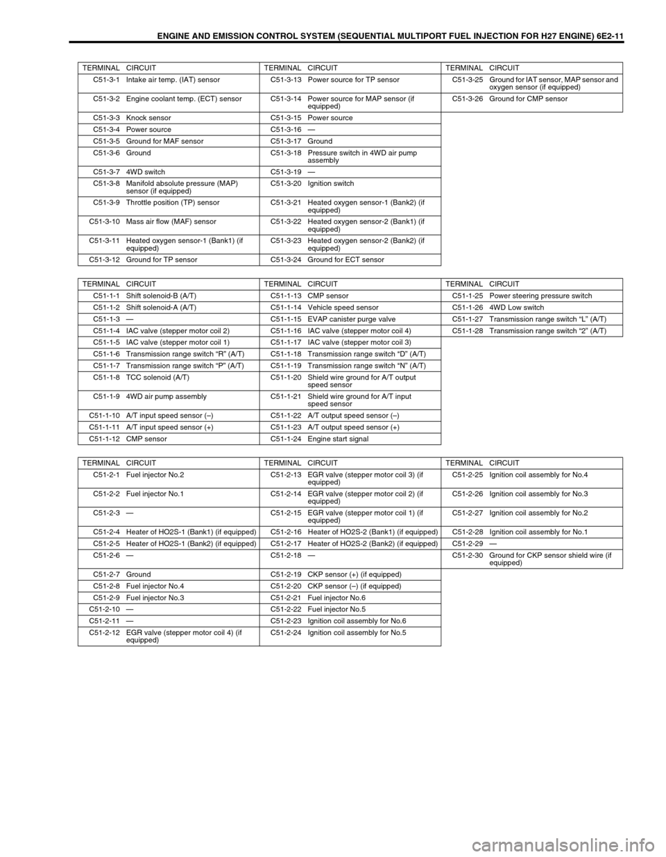
ENGINE AND EMISSION CONTROL SYSTEM (SEQUENTIAL MULTIPORT FUEL INJECTION FOR H27 ENGINE) 6E2-11
TERMINAL CIRCUIT TERMINAL CIRCUIT TERMINAL CIRCUIT
C51-3-1 Intake air temp. (IAT) sensor C51-3-13 Power source for TP sensor C51-3-25 Ground for IAT sensor, MAP sensor and
oxygen sensor (if equipped)
C51-3-2 Engine coolant temp. (ECT) sensor C51-3-14 Power source for MAP sensor (if
equipped)C51-3-26 Ground for CMP sensor
C51-3-3 Knock sensor C51-3-15 Power source
C51-3-4 Power source C51-3-16—
C51-3-5 Ground for MAF sensor C51-3-17 Ground
C51-3-6 Ground C51-3-18 Pressure switch in 4WD air pump
assembly
C51-3-7 4WD switch C51-3-19—
C51-3-8 Manifold absolute pressure (MAP)
sensor (if equipped)C51-3-20 Ignition switch
C51-3-9 Throttle position (TP) sensor C51-3-21 Heated oxygen sensor-1 (Bank2) (if
equipped)
C51-3-10 Mass air flow (MAF) sensor C51-3-22 Heated oxygen sensor-2 (Bank1) (if
equipped)
C51-3-11 Heated oxygen sensor-1 (Bank1) (if
equipped)C51-3-23 Heated oxygen sensor-2 (Bank2) (if
equipped)
C51-3-12 Ground for TP sensor C51-3-24 Ground for ECT sensor
TERMINAL CIRCUIT TERMINAL CIRCUIT TERMINAL CIRCUIT
C51-1-1 Shift solenoid-B (A/T) C51-1-13 CMP sensor C51-1-25 Power steering pressure switch
C51-1-2 Shift solenoid-A (A/T) C51-1-14 Vehicle speed sensor C51-1-26 4WD Low switch
C51-1-3—C51-1-15 EVAP canister purge valve C51-1-27 Transmission range switch “L” (A/T)
C51-1-4 IAC valve (stepper motor coil 2) C51-1-16 IAC valve (stepper motor coil 4) C51-1-28 Transmission range switch “2” (A/T)
C51-1-5 IAC valve (stepper motor coil 1) C51-1-17 IAC valve (stepper motor coil 3)
C51-1-6 Transmission range switch “R” (A/T) C51-1-18 Transmission range switch “D” (A/T)
C51-1-7 Transmission range switch “P” (A/T) C51-1-19 Transmission range switch “N” (A/T)
C51-1-8 TCC solenoid (A/T) C51-1-20 Shield wire ground for A/T output
speed sensor
C51-1-9 4WD air pump assembly C51-1-21 Shield wire ground for A/T input
speed sensor
C51-1-10 A/T input speed sensor (–) C51-1-22 A/T output speed sensor (–)
C51-1-11 A/T input speed sensor (+) C51-1-23 A/T output speed sensor (+)
C51-1-12 CMP sensor C51-1-24 Engine start signal
TERMINAL CIRCUIT TERMINAL CIRCUIT TERMINAL CIRCUIT
C51-2-1 Fuel injector No.2 C51-2-13 EGR valve (stepper motor coil 3) (if
equipped)C51-2-25 Ignition coil assembly for No.4
C51-2-2 Fuel injector No.1 C51-2-14 EGR valve (stepper motor coil 2) (if
equipped)C51-2-26 Ignition coil assembly for No.3
C51-2-3—C51-2-15 EGR valve (stepper motor coil 1) (if
equipped)C51-2-27 Ignition coil assembly for No.2
C51-2-4 Heater of HO2S-1 (Bank1) (if equipped) C51-2-16 Heater of HO2S-2 (Bank1) (if equipped) C51-2-28 Ignition coil assembly for No.1
C51-2-5 Heater of HO2S-1 (Bank2) (if equipped) C51-2-17 Heater of HO2S-2 (Bank2) (if equipped) C51-2-29—
C51-2-6—C51-2-18—C51-2-30 Ground for CKP sensor shield wire (if
equipped)
C51-2-7 Ground C51-2-19 CKP sensor (+) (if equipped)
C51-2-8 Fuel injector No.4 C51-2-20 CKP sensor (–) (if equipped)
C51-2-9 Fuel injector No.3 C51-2-21 Fuel injector No.6
C51-2-10—C51-2-22 Fuel injector No.5
C51-2-11—C51-2-23 Ignition coil assembly for No.6
C51-2-12 EGR valve (stepper motor coil 4) (if
equipped)C51-2-24 Ignition coil assembly for No.5
Page 423 of 656
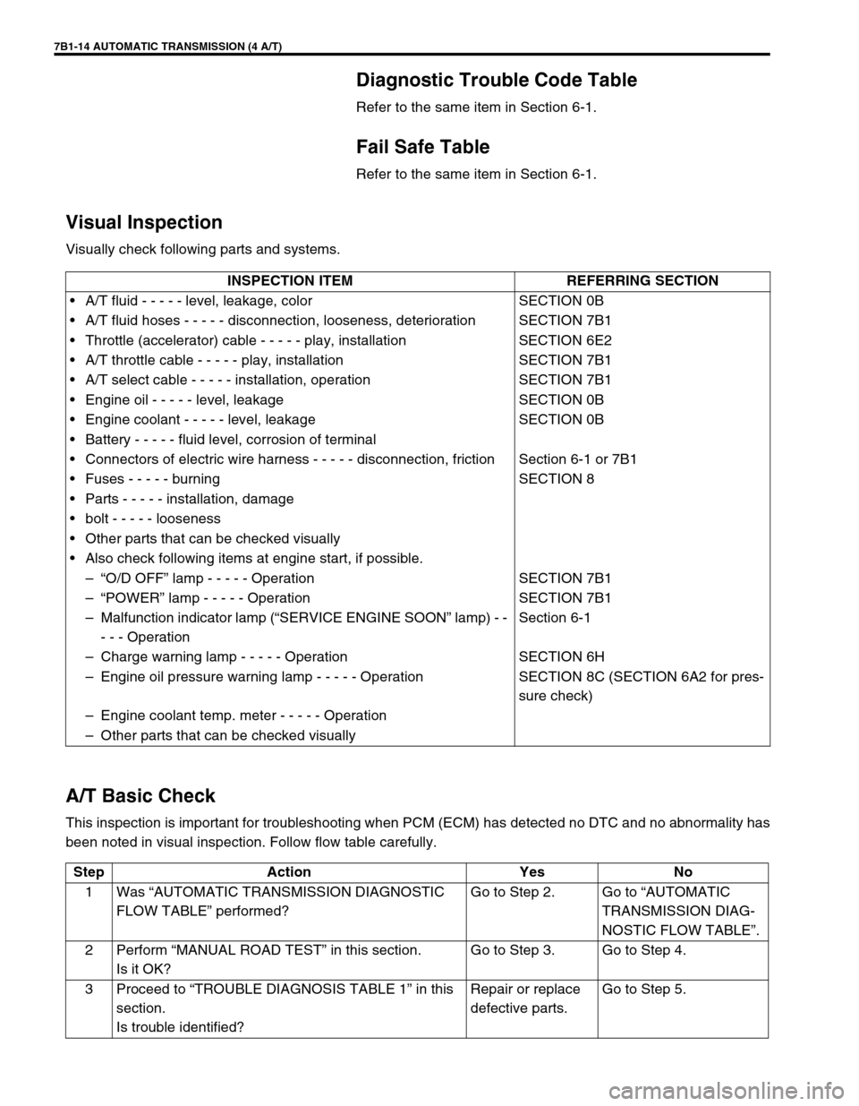
7B1-14 AUTOMATIC TRANSMISSION (4 A/T)
Diagnostic Trouble Code Table
Refer to the same item in Section 6-1.
Fail Safe Table
Refer to the same item in Section 6-1.
Visual Inspection
Visually check following parts and systems.
A/T Basic Check
This inspection is important for troubleshooting when PCM (ECM) has detected no DTC and no abnormality has
been noted in visual inspection. Follow flow table carefully.INSPECTION ITEM REFERRING SECTION
•A/T fluid - - - - - level, leakage, color SECTION 0B
•A/T fluid hoses - - - - - disconnection, looseness, deterioration SECTION 7B1
•Throttle (accelerator) cable - - - - - play, installation SECTION 6E2
•A/T throttle cable - - - - - play, installation SECTION 7B1
•A/T select cable - - - - - installation, operation SECTION 7B1
•Engine oil - - - - - level, leakage SECTION 0B
•Engine coolant - - - - - level, leakage SECTION 0B
•Battery - - - - - fluid level, corrosion of terminal
•Connectors of electric wire harness - - - - - disconnection, friction Section 6-1 or 7B1
•Fuses - - - - - burning SECTION 8
•Parts - - - - - installation, damage
•bolt - - - - - looseness
•Other parts that can be checked visually
•Also check following items at engine start, if possible.
–“O/D OFF” lamp - - - - - Operation SECTION 7B1
–“POWER” lamp - - - - - Operation SECTION 7B1
–Malfunction indicator lamp (“SERVICE ENGINE SOON” lamp) - -
- - - OperationSection 6-1
–Charge warning lamp - - - - - Operation SECTION 6H
–Engine oil pressure warning lamp - - - - - Operation SECTION 8C (SECTION 6A2 for pres-
sure check)
–Engine coolant temp. meter - - - - - Operation
–Other parts that can be checked visually
Step Action Yes No
1Was “AUTOMATIC TRANSMISSION DIAGNOSTIC
FLOW TABLE” performed?Go to Step 2. Go to “AUTOMATIC
TRANSMISSION DIAG-
NOSTIC FLOW TABLE”.
2Perform “MANUAL ROAD TEST” in this section.
Is it OK?Go to Step 3. Go to Step 4.
3Proceed to “TROUBLE DIAGNOSIS TABLE 1” in this
section.
Is trouble identified?Repair or replace
defective parts.Go to Step 5.
Page 424 of 656
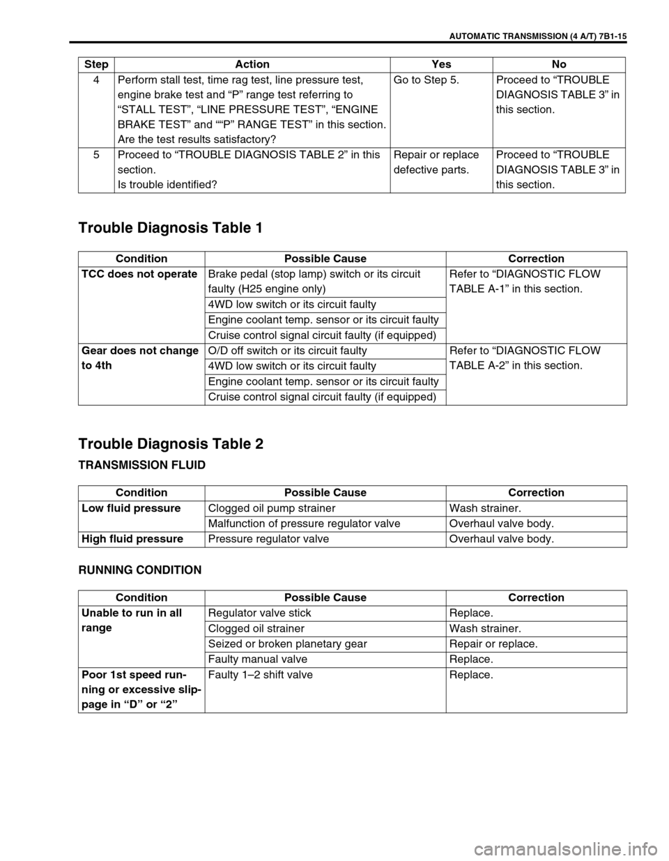
AUTOMATIC TRANSMISSION (4 A/T) 7B1-15
Trouble Diagnosis Table 1
Trouble Diagnosis Table 2
TRANSMISSION FLUID
RUNNING CONDITION
4 Perform stall test, time rag test, line pressure test,
engine brake test and “P” range test referring to
“STALL TEST”, “LINE PRESSURE TEST”, “ENGINE
BRAKE TEST” and ““P” RANGE TEST” in this section.
Are the test results satisfactory?Go to Step 5. Proceed to “TROUBLE
DIAGNOSIS TABLE 3” in
this section.
5 Proceed to “TROUBLE DIAGNOSIS TABLE 2” in this
section.
Is trouble identified?Repair or replace
defective parts.Proceed to “TROUBLE
DIAGNOSIS TABLE 3” in
this section. Step Action Yes No
Condition Possible Cause Correction
TCC does not operateBrake pedal (stop lamp) switch or its circuit
faulty (H25 engine only)Refer to “DIAGNOSTIC FLOW
TABLE A-1” in this section.
4WD low switch or its circuit faulty
Engine coolant temp. sensor or its circuit faulty
Cruise control signal circuit faulty (if equipped)
Gear does not change
to 4thO/D off switch or its circuit faulty Refer to “DIAGNOSTIC FLOW
TABLE A-2” in this section.
4WD low switch or its circuit faulty
Engine coolant temp. sensor or its circuit faulty
Cruise control signal circuit faulty (if equipped)
Condition Possible Cause Correction
Low fluid pressureClogged oil pump strainer Wash strainer.
Malfunction of pressure regulator valve Overhaul valve body.
High fluid pressurePressure regulator valve Overhaul valve body.
Condition Possible Cause Correction
Unable to run in all
rangeRegulator valve stick Replace.
Clogged oil strainer Wash strainer.
Seized or broken planetary gear Repair or replace.
Faulty manual valve Replace.
Poor 1st speed run-
ning or excessive slip-
page in “D” or “2”Faulty 1–2 shift valve Replace.
Page 425 of 656
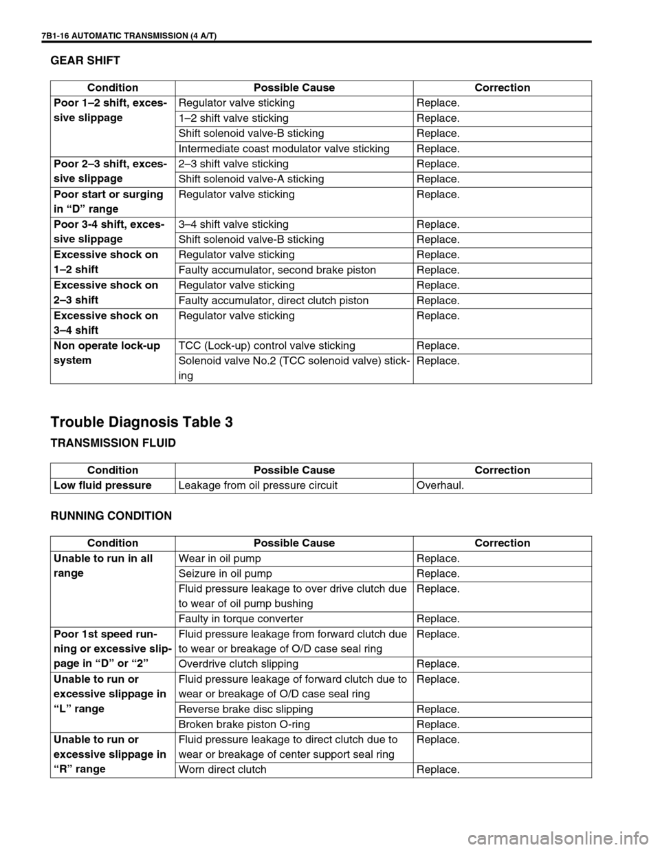
7B1-16 AUTOMATIC TRANSMISSION (4 A/T)
GEAR SHIFT
Trouble Diagnosis Table 3
TRANSMISSION FLUID
RUNNING CONDITION
Condition Possible Cause Correction
Poor 1–2 shift, exces-
sive slippageRegulator valve sticking Replace.
1–2 shift valve sticking Replace.
Shift solenoid valve-B sticking Replace.
Intermediate coast modulator valve sticking Replace.
Poor 2–3 shift, exces-
sive slippage2–3 shift valve sticking Replace.
Shift solenoid valve-A sticking Replace.
Poor start or surging
in “D” rangeRegulator valve sticking Replace.
Poor 3-4 shift, exces-
sive slippage3–4 shift valve sticking Replace.
Shift solenoid valve-B sticking Replace.
Excessive shock on
1–2 shiftRegulator valve sticking Replace.
Faulty accumulator, second brake piston Replace.
Excessive shock on
2–3 shiftRegulator valve sticking Replace.
Faulty accumulator, direct clutch piston Replace.
Excessive shock on
3–4 shiftRegulator valve sticking Replace.
Non operate lock-up
systemTCC (Lock-up) control valve sticking Replace.
Solenoid valve No.2 (TCC solenoid valve) stick-
ingReplace.
Condition Possible Cause Correction
Low fluid pressureLeakage from oil pressure circuit Overhaul.
Condition Possible Cause Correction
Unable to run in all
rangeWear in oil pump Replace.
Seizure in oil pump Replace.
Fluid pressure leakage to over drive clutch due
to wear of oil pump bushingReplace.
Faulty in torque converter Replace.
Poor 1st speed run-
ning or excessive slip-
page in “D” or “2”Fluid pressure leakage from forward clutch due
to wear or breakage of O/D case seal ringReplace.
Overdrive clutch slipping Replace.
Unable to run or
excessive slippage in
“L” rangeFluid pressure leakage of forward clutch due to
wear or breakage of O/D case seal ringReplace.
Reverse brake disc slipping Replace.
Broken brake piston O-ring Replace.
Unable to run or
excessive slippage in
“R” rangeFluid pressure leakage to direct clutch due to
wear or breakage of center support seal ringReplace.
Worn direct clutch Replace.
Page 448 of 656
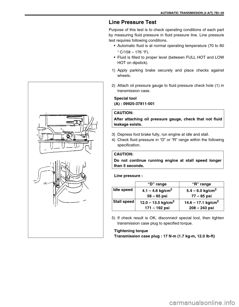
AUTOMATIC TRANSMISSION (4 A/T) 7B1-39
Line Pressure Test
Purpose of this test is to check operating conditions of each part
by measuring fluid pressure in fluid pressure line. Line pressure
test requires following conditions.
•Automatic fluid is at normal operating temperature (70 to 80
°
C/158 – 176 °F).
•Fluid is filled to proper level (between FULL HOT and LOW
HOT on dipstick).
1) Apply parking brake securely and place checks against
wheels.
2) Attach oil pressure gauge to fluid pressure check hole (1) in
transmission case.
Special tool
(A) : 09925-37811-001
3) Depress foot brake fully, run engine at idle and stall.
4) Check fluid pressure in “D” or “R” range within the following
specification.
Line pressure :
5) If check result is OK, disconnect special tool, then tighten
transmission case plug to specified torque.
Tightening torque
Transmission case plug : 17 N·m (1.7 kg-m, 12.0 lb-ft) CAUTION:
After attaching oil pressure gauge, check that not fluid
leakage exists.
CAUTION:
Do not continue running engine at stall speed longer
than 5 seconds.
“D” range“R” range
Idle speed
4.1 – 4.6 kg/cm
2
58 – 65 psi5.4 – 6.0 kg/cm
2
77 – 85 psi
Stall speed
12.0 – 13.5 kg/cm
2
171 – 192 psi14.6 – 17.1 kg/cm
2
208 – 243 psi
Page 449 of 656
7B1-40 AUTOMATIC TRANSMISSION (4 A/T)
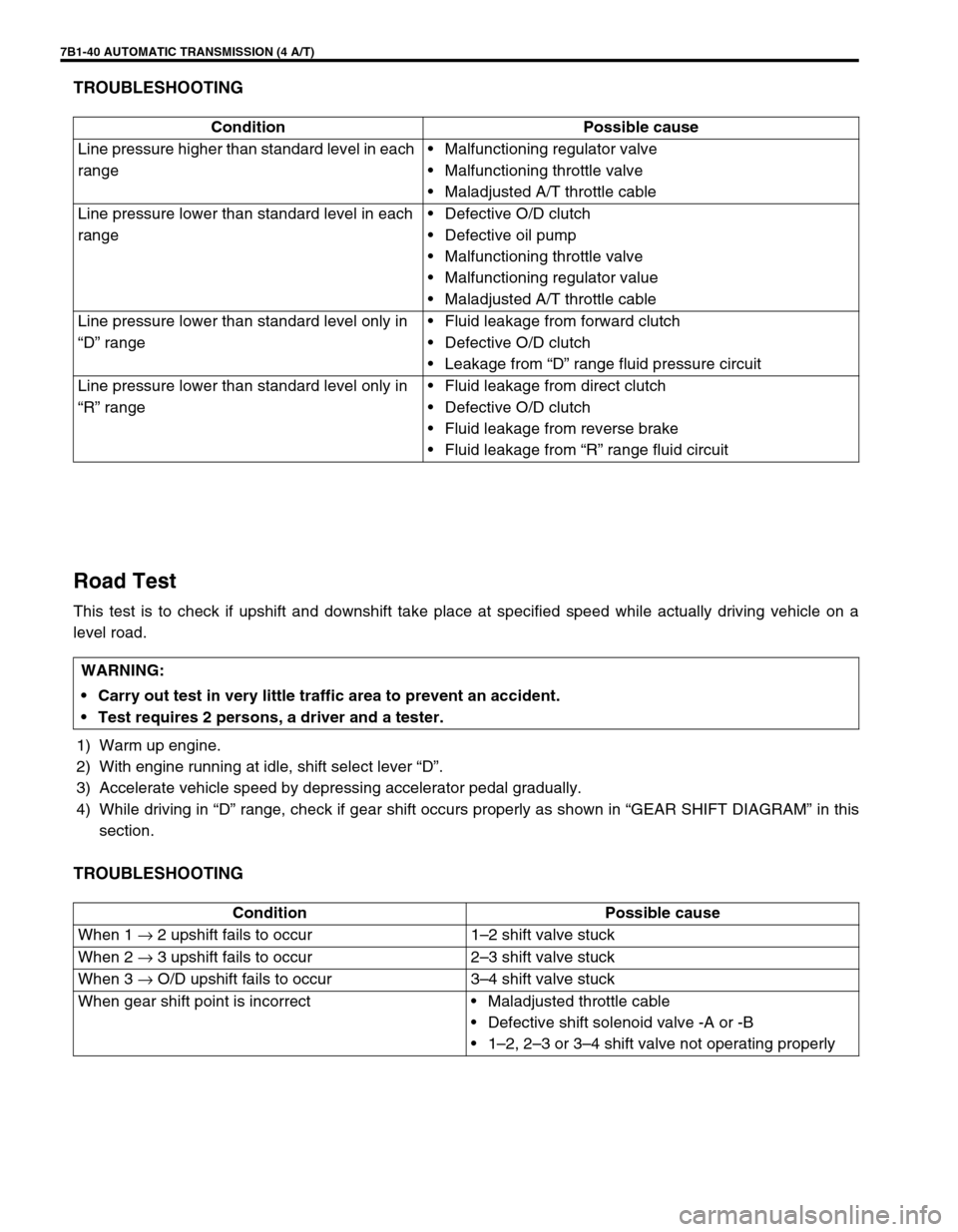
TROUBLESHOOTING
Road Test
This test is to check if upshift and downshift take place at specified speed while actually driving vehicle on a
level road.
1) Warm up engine.
2) With engine running at idle, shift select lever “D”.
3) Accelerate vehicle speed by depressing accelerator pedal gradually.
4) While driving in “D” range, check if gear shift occurs properly as shown in “GEAR SHIFT DIAGRAM” in this
section.
TROUBLESHOOTING
Condition Possible cause
Line pressure higher than standard level in each
range•Malfunctioning regulator valve
•Malfunctioning throttle valve
•Maladjusted A/T throttle cable
Line pressure lower than standard level in each
range•Defective O/D clutch
•Defective oil pump
•Malfunctioning throttle valve
•Malfunctioning regulator value
•Maladjusted A/T throttle cable
Line pressure lower than standard level only in
“D” range•Fluid leakage from forward clutch
•Defective O/D clutch
•Leakage from “D” range fluid pressure circuit
Line pressure lower than standard level only in
“R” range•Fluid leakage from direct clutch
•Defective O/D clutch
•Fluid leakage from reverse brake
•Fluid leakage from “R” range fluid circuit
WARNING:
Carry out test in very little traffic area to prevent an accident.
Test requires 2 persons, a driver and a tester.
Condition Possible cause
When 1 → 2 upshift fails to occur 1–2 shift valve stuck
When 2 → 3 upshift fails to occur 2–3 shift valve stuck
When 3 → O/D upshift fails to occur 3–4 shift valve stuck
When gear shift point is incorrect•Maladjusted throttle cable
•Defective shift solenoid valve -A or -B
•1–2, 2–3 or 3–4 shift valve not operating properly
Page 463 of 656

7B1-54 AUTOMATIC TRANSMISSION (4 A/T)
6) Install direct clutch cylinder to center support.
Remove direct clutch piston by blowing air into the second
hole from the left as shown in the figure. Also, remove direct
clutch inner piston by blowing air into hole at the extreme
right. And then remove O-rings from pistons.
Front upper valve body
ASSEMBLY
Assemble each component by reversing disassembly procedure
and noting the following points.
•Coil outer diameter and free length of each valve spring
should be as listed below. Be sure to use each one of correct
size.
Coil outer diameter and free length of each valve spring
•Install as many throttle valve compensating rings as written
down when disassembled.
•Tighten throttle cam bolt (1) to specified torque.
Tightening torque
Throttle cam bolt (a) : 7.5 N·m (0.75 kg-m, 5.5 lb-ft)
•Tighten pressure relief valve bolts (1) to specified torque.
Tightening torque
Pressure relief valve bolt (b) : 5.5 N·m (0.55 kg-m, 4.0 lb-ft)
Name of spring Outer diameter Free length
Secondary regulator
valve spring17.43 mm
(0.681 in.)71.27 mm
(2.806 in.)
Cut back valve spring 6.85 mm
(0.259 in.)23.0 mm
(0.906 in.)
Throttle valve
secondary spring8.56 mm
(0.337 in.)18.86 mm
(0.743 in.)
Throttle valve
primary spring10.90 mm
(0.429 in.)39.55 mm
(1.557 in.)