wheel torque SUZUKI GRAND VITARA 2001 2.G Owner's Manual
[x] Cancel search | Manufacturer: SUZUKI, Model Year: 2001, Model line: GRAND VITARA, Model: SUZUKI GRAND VITARA 2001 2.GPages: 656, PDF Size: 14.31 MB
Page 126 of 656
ANTILOCK BRAKE SYSTEM (ABS) 5E2-1
5E2
SECTION 5E2
ANTILOCK BRAKE SYSTEM (ABS)
CONTENTS
General Description ..................................... 5E2-3
Components/Parts Location ....................... 5E2-3
ABS Hydraulic Unit/control Module
Assembly .................................................... 5E2-4
Self-diagnosis function ........................... 5E2-4
Fail-safe function .................................... 5E2-5
Diagnosis ...................................................... 5E2-5
Precautions in Diagnosing Troubles .......... 5E2-5
ABS Diagnostic Flow Table ........................ 5E2-6
ABS Warning Lamp Check ........................ 5E2-9
EBD Warning Lamp (Brake Warning Lamp)
Check ......................................................... 5E2-9
Diagnostic Trouble Code (DTC) Check
(Using ABS Warning Lamp) ..................... 5E2-10
Diagnostic Trouble Code (DTC) Check
(Using SUZUKI Scan Tool) ...................... 5E2-11
Diagnostic Trouble Code (DTC)
Clearance ................................................. 5E2-11
Diagnostic Trouble Code (DTC) Table ..... 5E2-12
System Circuit .......................................... 5E2-14Table-A ABS Warning Lamp Circuit Check
– Lamp Does Not Come “ON” at Ignition
Switch ON ................................................ 5E2-15
Table-B ABS Warning Lamp Circuit Check
– Lamp Comes “ON” Steady.................... 5E2-16
Table-C ABS Warning Lamp Circuit Check
– The Lamp Flashes Continuously While
Ignition Switch Is ON ................................ 5E2-17
Table-D Code (DTC) Is Not Outputted
Even with Diagnosis Switch Terminal
Connected to Ground............................... 5E2-18
Table-E EBD Warning Lamp (Brake
Warning Lamp) Check – Lamp Comes
“ON” Steady ............................................. 5E2-19
DTC C1015 (DTC 15) – G Sensor Circuit
and 4WD Lamp Circuit ............................. 5E2-20
DTC C1021 (DTC 21), DTC C1022
(DTC 22) – Right-Front Wheel Speed
Sensor Circuit or Sensor Ring ................. 5E2-22
DTC C1025 (DTC 25), DTC C1026
(DTC 26) – Left-Front Wheel Speed WARNING:
For vehicles equipped with Supplemental Restraint (Air Bag) System:
Service on and around the air bag system components or wiring must be performed only by an
authorized SUZUKI dealer. Refer to “Air Bag System Components and Wiring Location View” under
“General Description” in air bag system section in order to confirm whether you are performing ser-
vice on or near the air bag system components or wiring. Please observe all WARNINGS and “Ser-
vice Precautions” under “On-Vehicle Service” in air bag system section before performing service
on or around the air bag system components or wiring. Failure to follow WARNINGS could result in
unintentional activation of the system or could render the system inoperative. Either of these two
conditions may result in severe injury.
Technical service work must be started at least 90 seconds after the ignition switch is turned to the
“LOCK” position and the negative cable is disconnected from the battery. Otherwise, the system
may be activated by reserve energy in the Sensing and Diagnostic Module (SDM).
NOTE:
For the descriptions (items) not found in this section, refer to Section 5E1 of the Service Manual
mentioned in the FOREWORD of this manual.
All brake fasteners are important attaching parts in that they could affect the performance of vital
parts and systems, and/or could result in major repair expense. They must be replaced with one of
same part number or with an equivalent part if replacement becomes necessary. Do not use a
replacement part of lesser quality or substitute design. Torque values must be used as specified
during reassembly to assure proper retention of all parts. There is to be no welding as it may result
in extensive damage and weakening of the metal.
Page 127 of 656
5E2-2 ANTILOCK BRAKE SYSTEM (ABS)
Sensor Circuit or Sensor Ring ................. 5E2-22
DTC C1031 (DTC 31), DTC C1032
(DTC 32) – Right-Rear Wheel Speed
Sensor Circuit or Sensor Ring ................. 5E2-22
DTC C1035 (DTC 35), DTC C1036
(DTC 36) – Left-Rear Wheel Speed
Sensor Circuit or Sensor Ring ................. 5E2-22
DTC C1041 (DTC 41) – Right-Front Inlet
Solenoid Circuit ........................................ 5E2-24
DTC C1045 (DTC 45) – Left-Front Inlet
Solenoid Circuit ........................................ 5E2-24
DTC C1055 (DTC 55) – Rear Inlet
Solenoid Circuit ........................................ 5E2-24
DTC C1042 (DTC 42) – Right-Front
Outlet Solenoid Circuit ............................. 5E2-24
DTC C1046 (DTC 46) – Left-Front Outlet
Solenoid Circuit ........................................ 5E2-24
DTC C1056 (DTC 56) – Rear Outlet
Solenoid Circuit ........................................ 5E2-24
DTC C1057 (DTC 57) – Power Source Circuit....................................................... 5E2-25
DTC C1061 (DTC 61) – ABS Pump Motor
Circuit....................................................... 5E2-26
DTC C1063 (DTC 63) – ABS Fail-Safe
Relay Circuit ............................................ 5E2-27
DTC C1071 (DTC 71) – ABS Control
Module ..................................................... 5E2-28
On-Vehicle Service .................................... 5E2-29
Precautions .............................................. 5E2-29
ABS Hydraulic Unit Operation Check
(Using SUZUKI Scan Tool) ...................... 5E2-29
ABS Hydraulic Unit Operation Check
(Not Using Suzuki Scan Tool).................. 5E2-29
ABS Hydraulic Unit/Control Module
Assembly ................................................. 5E2-31
Rear Sensor Rotor (Retainer Ring) ......... 5E2-33
Tightening Torque Specification.............. 5E2-34
Special Tool ............................................... 5E2-34
Page 148 of 656
ANTILOCK BRAKE SYSTEM (ABS) 5E2-23
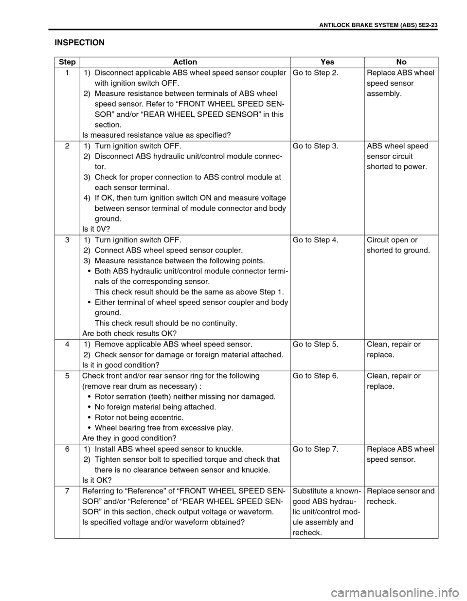
INSPECTION
Step Action Yes No
1 1) Disconnect applicable ABS wheel speed sensor coupler
with ignition switch OFF.
2) Measure resistance between terminals of ABS wheel
speed sensor. Refer to “FRONT WHEEL SPEED SEN-
SOR” and/or “REAR WHEEL SPEED SENSOR” in this
section.
Is measured resistance value as specified?Go to Step 2. Replace ABS wheel
speed sensor
assembly.
2 1) Turn ignition switch OFF.
2) Disconnect ABS hydraulic unit/control module connec-
tor.
3) Check for proper connection to ABS control module at
each sensor terminal.
4) If OK, then turn ignition switch ON and measure voltage
between sensor terminal of module connector and body
ground.
Is it 0V?Go to Step 3. ABS wheel speed
sensor circuit
shorted to power.
3 1) Turn ignition switch OFF.
2) Connect ABS wheel speed sensor coupler.
3) Measure resistance between the following points.
Both ABS hydraulic unit/control module connector termi-
nals of the corresponding sensor.
This check result should be the same as above Step 1.
Either terminal of wheel speed sensor coupler and body
ground.
This check result should be no continuity.
Are both check results OK?Go to Step 4. Circuit open or
shorted to ground.
4 1) Remove applicable ABS wheel speed sensor.
2) Check sensor for damage or foreign material attached.
Is it in good condition?Go to Step 5. Clean, repair or
replace.
5 Check front and/or rear sensor ring for the following
(remove rear drum as necessary) :
Rotor serration (teeth) neither missing nor damaged.
No foreign material being attached.
Rotor not being eccentric.
Wheel bearing free from excessive play.
Are they in good condition?Go to Step 6. Clean, repair or
replace.
6 1) Install ABS wheel speed sensor to knuckle.
2) Tighten sensor bolt to specified torque and check that
there is no clearance between sensor and knuckle.
Is it OK?Go to Step 7. Replace ABS wheel
speed sensor.
7 Referring to “Reference” of “FRONT WHEEL SPEED SEN-
SOR” and/or “Reference” of “REAR WHEEL SPEED SEN-
SOR” in this section, check output voltage or waveform.
Is specified voltage and/or waveform obtained?Substitute a known-
good ABS hydrau-
lic unit/control mod-
ule assembly and
recheck.Replace sensor and
recheck.
Page 159 of 656
5E2-34 ANTILOCK BRAKE SYSTEM (ABS)
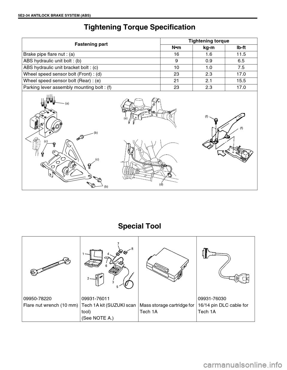
Tightening Torque Specification
Special Tool
Fastening partTightening torque
Nm kg-m lb-ft
Brake pipe flare nut : (a) 16 1.6 11.5
ABS hydraulic unit bolt : (b) 9 0.9 6.5
ABS hydraulic unit bracket bolt : (c) 10 1.0 7.5
Wheel speed sensor bolt (Front) : (d) 23 2.3 17.0
Wheel speed sensor bolt (Rear) : (e) 21 2.1 15.5
Parking lever assembly mounting bolt : (f) 23 2.3 17.0
(b) (b) (a)
(c) (c)
09950-78220 09931-76011 09931-76030
Flare nut wrench (10 mm) Tech 1A kit (SUZUKI scan
tool)
(See NOTE A.)Mass storage cartridge for
Tech 1A16/14 pin DLC cable for
Tech 1A
Page 306 of 656
ENGINE MECHANICAL (H27 ENGINE) 6A2-19
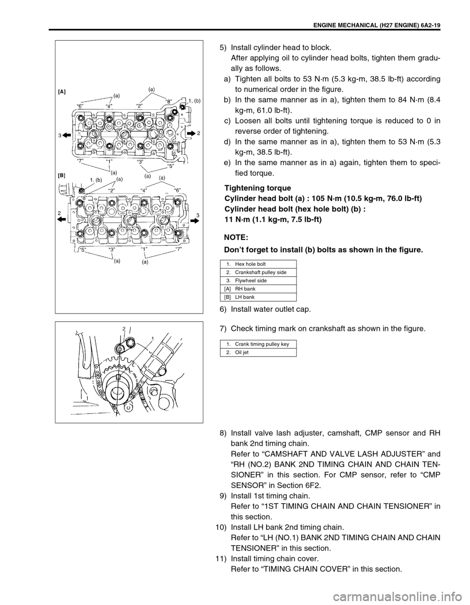
5) Install cylinder head to block.
After applying oil to cylinder head bolts, tighten them gradu-
ally as follows.
a) Tighten all bolts to 53 N·m (5.3 kg-m, 38.5 lb-ft) according
to numerical order in the figure.
b) In the same manner as in a), tighten them to 84 N·m (8.4
kg-m, 61.0 lb-ft).
c) Loosen all bolts until tightening torque is reduced to 0 in
reverse order of tightening.
d) In the same manner as in a), tighten them to 53 N·m (5.3
kg-m, 38.5 lb-ft).
e) In the same manner as in a) again, tighten them to speci-
fied torque.
Tightening torque
Cylinder head bolt (a) : 105 N·m (10.5 kg-m, 76.0 lb-ft)
Cylinder head bolt (hex hole bolt) (b) :
11 N·m (1.1 kg-m, 7.5 lb-ft)
6) Install water outlet cap.
7) Check timing mark on crankshaft as shown in the figure.
8) Install valve lash adjuster, camshaft, CMP sensor and RH
bank 2nd timing chain.
Refer to “CAMSHAFT AND VALVE LASH ADJUSTER” and
“RH (NO.2) BANK 2ND TIMING CHAIN AND CHAIN TEN-
SIONER” in this section. For CMP sensor, refer to “CMP
SENSOR” in Section 6F2.
9) Install 1st timing chain.
Refer to “1ST TIMING CHAIN AND CHAIN TENSIONER” in
this section.
10) Install LH bank 2nd timing chain.
Refer to “LH (NO.1) BANK 2ND TIMING CHAIN AND CHAIN
TENSIONER” in this section.
11) Install timing chain cover.
Refer to “TIMING CHAIN COVER” in this section. NOTE:
Don’t forget to install (b) bolts as shown in the figure.
1. Hex hole bolt
2. Crankshaft pulley side
3. Flywheel side
[A] RH bank
[B] LH bank
1. Crank timing pulley key
2. Oil jet
Page 317 of 656

6A2-30 ENGINE MECHANICAL (H27 ENGINE)
Main Bearings, Crankshaft and Cylinder Block
1. Cylinder block 6. Rear oil seal 11. O-ring [A]: Sealant application amount
2. Lower crankcase :
Apply sealant 99000-31150 to lower
crankcase mating surface.7. Flywheel (M/T) Drive plate
(A/T)12. Clutch housing plate Tightening Torque
3. Crankshaft 8. Water pump 13. Cap bolt Do not reuse
4. Main bearing 9. O-ring 14. Lower crankcase bolt Apply engine oil to sliding
surface of each parts.
5. Thrust bearing :
Set bearing facing grooved side to
crank weds.10. Timing chain oil jet 15. Knock sensor“a”: Width 3 mm (0.12 in.)
“b”: Height 2 mm (0.08 in.)
Page 447 of 656
7B1-38 AUTOMATIC TRANSMISSION (4 A/T)
Stall Test
This test is to check overall performance of automatic transmission and engine by measuring stall speed at “D”
and “R” ranges. Be sure to perform this test only when transmission fluid is at normal operating temperature and
its level is between FULL and LOW marks.
1) Apply parking brake and block wheels.
2) Install tachometer.
3) Start engine with select lever shifted to “P”.
4) Depress brake pedal fully.
5) Shift select lever to “D” and depress accelerator pedal fully while watching tachometer. Read engine rpm
quickly when it has become constant (stall speed).
6) Release accelerator pedal immediately after stall speed is checked.
7) In the same way, check stall speed in “R” range.
8) Stall speed should be within the following specification.
Stall speed :
2,460 – 2,760 r/min.
TROUBLESHOOTING
CAUTION:
Do not run engine at stall more than 5 seconds continuously, for fluid temperature may rise exces-
sively high.
After performing stall test, be sure to leave engine running at idle for longer than 30 seconds before
another stall test.
Condition Possible cause
Lower than standard level•Faulty engine output
•Defective torque converter
Higher than standard level in “D” range•Slippery O/D clutch
•Slippery forward clutch
•Malfunctioning O/D one-way clutch
•Malfunctioning one-way clutch No. 2
•Low line pressure
Higher than standard level in “R” range•Slippery direct clutch
•Slippery reverse brake
•Low fluid pressure
•Slippery O/D clutch
•Defective O/D one-way clutch
Page 448 of 656
AUTOMATIC TRANSMISSION (4 A/T) 7B1-39
Line Pressure Test
Purpose of this test is to check operating conditions of each part
by measuring fluid pressure in fluid pressure line. Line pressure
test requires following conditions.
•Automatic fluid is at normal operating temperature (70 to 80
°
C/158 – 176 °F).
•Fluid is filled to proper level (between FULL HOT and LOW
HOT on dipstick).
1) Apply parking brake securely and place checks against
wheels.
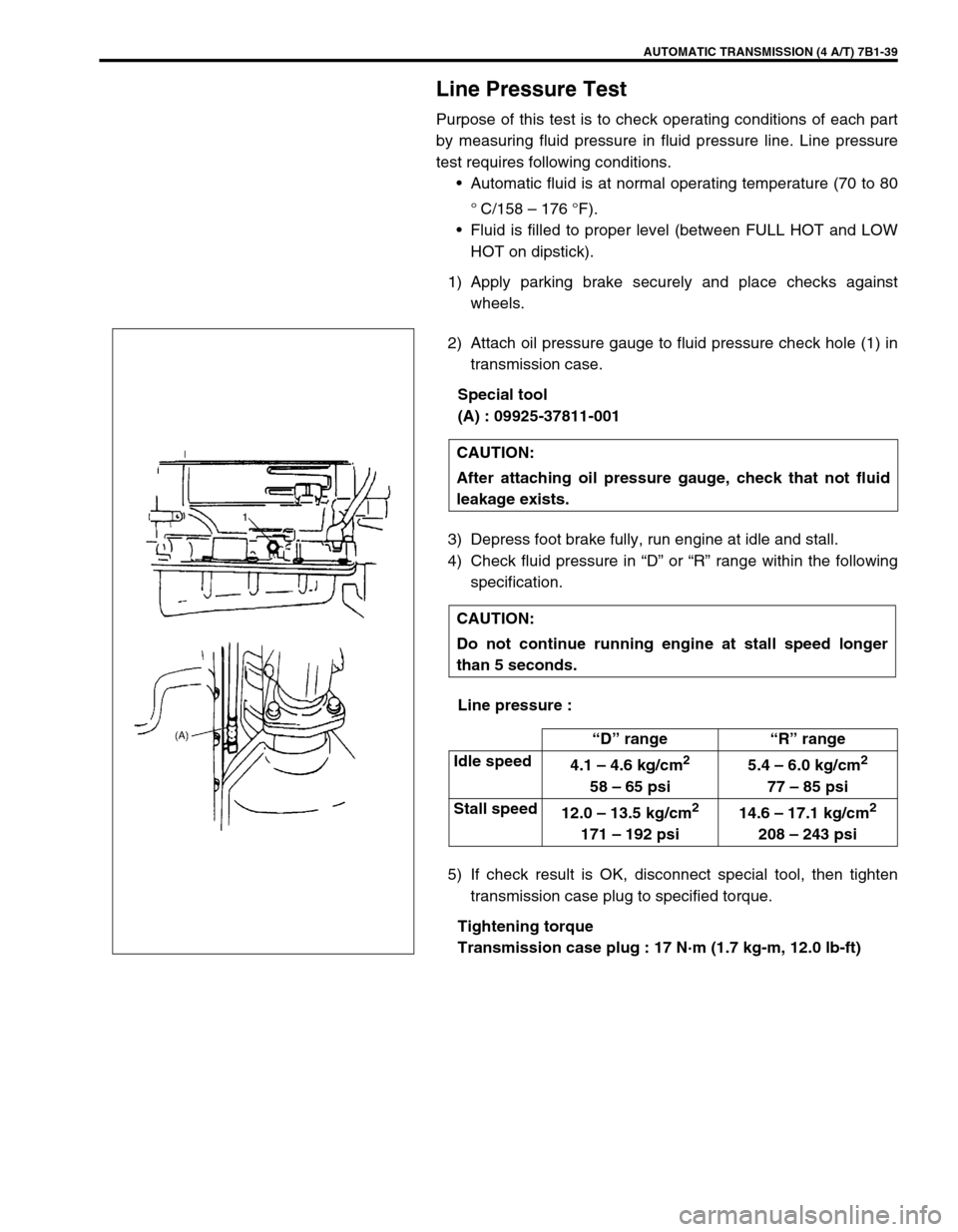
2) Attach oil pressure gauge to fluid pressure check hole (1) in
transmission case.
Special tool
(A) : 09925-37811-001
3) Depress foot brake fully, run engine at idle and stall.
4) Check fluid pressure in “D” or “R” range within the following
specification.
Line pressure :
5) If check result is OK, disconnect special tool, then tighten
transmission case plug to specified torque.
Tightening torque
Transmission case plug : 17 N·m (1.7 kg-m, 12.0 lb-ft) CAUTION:
After attaching oil pressure gauge, check that not fluid
leakage exists.
CAUTION:
Do not continue running engine at stall speed longer
than 5 seconds.
“D” range“R” range
Idle speed
4.1 – 4.6 kg/cm
2
58 – 65 psi5.4 – 6.0 kg/cm
2
77 – 85 psi
Stall speed
12.0 – 13.5 kg/cm
2
171 – 192 psi14.6 – 17.1 kg/cm
2
208 – 243 psi
Page 491 of 656
7F-6 DIFFERENTIAL (REAR)
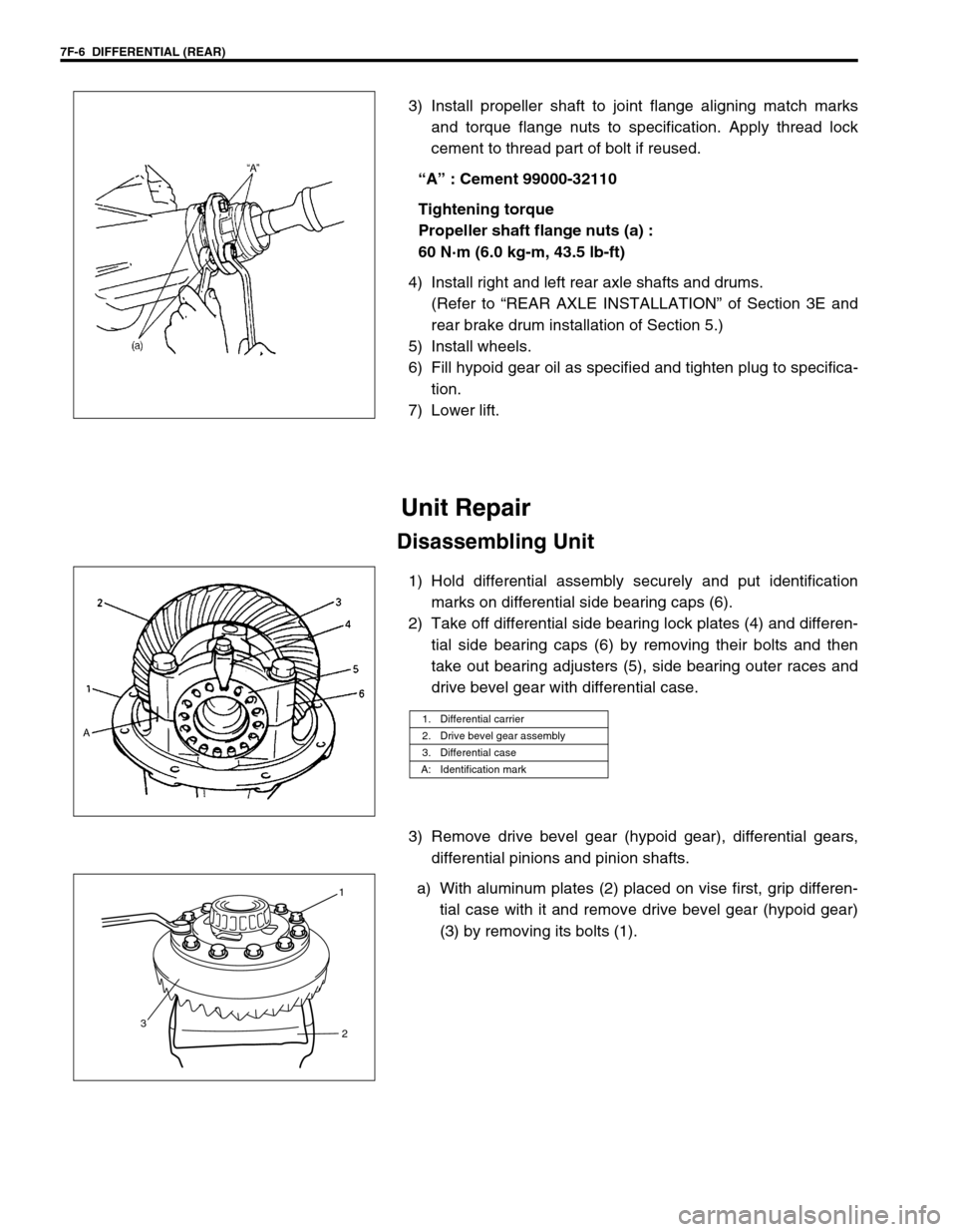
3) Install propeller shaft to joint flange aligning match marks
and torque flange nuts to specification. Apply thread lock
cement to thread part of bolt if reused.
“A” : Cement 99000-32110
Tightening torque
Propeller shaft flange nuts (a) :
60 N·m (6.0 kg-m, 43.5 lb-ft)
4) Install right and left rear axle shafts and drums.
(Refer to “REAR AXLE INSTALLATION” of Section 3E and
rear brake drum installation of Section 5.)
5) Install wheels.
6) Fill hypoid gear oil as specified and tighten plug to specifica-
tion.
7) Lower lift.
Unit Repair
Disassembling Unit
1) Hold differential assembly securely and put identification
marks on differential side bearing caps (6).
2) Take off differential side bearing lock plates (4) and differen-
tial side bearing caps (6) by removing their bolts and then
take out bearing adjusters (5), side bearing outer races and
drive bevel gear with differential case.
3) Remove drive bevel gear (hypoid gear), differential gears,
differential pinions and pinion shafts.
a) With aluminum plates (2) placed on vise first, grip differen-
tial case with it and remove drive bevel gear (hypoid gear)
(3) by removing its bolts (1).
1. Differential carrier
2. Drive bevel gear assembly
3. Differential case
A: Identification mark
1
3
2