Operation SUZUKI GRAND VITARA 2001 2.G Repair Manual
[x] Cancel search | Manufacturer: SUZUKI, Model Year: 2001, Model line: GRAND VITARA, Model: SUZUKI GRAND VITARA 2001 2.GPages: 656, PDF Size: 14.31 MB
Page 628 of 656
AIR BAG SYSTEM 10B-51
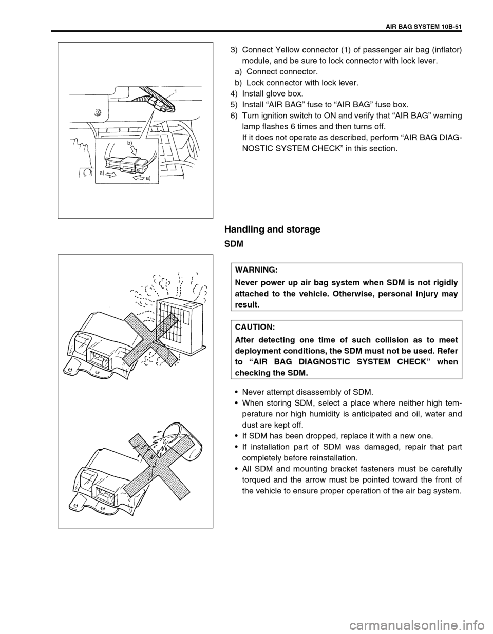
3) Connect Yellow connector (1) of passenger air bag (inflator)
module, and be sure to lock connector with lock lever.
a) Connect connector.
b) Lock connector with lock lever.
4) Install glove box.
5) Install “AIR BAG” fuse to “AIR BAG” fuse box.
6) Turn ignition switch to ON and verify that “AIR BAG” warning
lamp flashes 6 times and then turns off.
If it does not operate as described, perform “AIR BAG DIAG-
NOSTIC SYSTEM CHECK” in this section.
Handling and storage
SDM
•Never attempt disassembly of SDM.
•When storing SDM, select a place where neither high tem-
perature nor high humidity is anticipated and oil, water and
dust are kept off.
•If SDM has been dropped, replace it with a new one.
•If installation part of SDM was damaged, repair that part
completely before reinstallation.
•All SDM and mounting bracket fasteners must be carefully
torqued and the arrow must be pointed toward the front of
the vehicle to ensure proper operation of the air bag system.
WARNING:
Never power up air bag system when SDM is not rigidly
attached to the vehicle. Otherwise, personal injury may
result.
CAUTION:
After detecting one time of such collision as to meet
deployment conditions, the SDM must not be used. Refer
to “AIR BAG DIAGNOSTIC SYSTEM CHECK” when
checking the SDM.
Page 633 of 656

10B-56 AIR BAG SYSTEM
Repairs and Inspections Required after an Accident
Accident with deployment/activation - component replacement
Certain air bag system components must be replaced. Those components are:
•Driver and passenger air bag (inflator) modules
–Replace with new one.
•Driver and Passenger seat belt pretensioners
–Replace with new one.
•SDM after detecting such collision as to meet deployment conditions
–Replace with new one.
•Forward sensors
–Replace with new one. CAUTION:
All air bag system components, including the electrical harness (component mounting points),
must be inspected after an accident. If any components are damaged or bent, they must be replaced
even if air bag system activation did not occur.
Never use air bag system parts from another vehicle.
Do not attempt to service the parts below. Service of these parts is by replacement only.
–Driver/Passenger air bag (inflator) modules, Driver/Passenger seat belt pretensioners
–Forward sensors
–SDM
–Contact coil and combination switch assembly
–Air bag wire harness
Proper operation of the sensors and air bag system requires that any repairs to the vehicle struc-
ture return it to its original production configuration.
CAUTION:
After detecting one time of such collision as to meet deployment conditions, the SDM must not be
used.
Refer to “AIR BAG DIAGNOSTIC SYSTEM CHECK” when checking the SDM.
Page 639 of 656

10B-62 AIR BAG SYSTEM
Forward Sensor
REMOVAL
1) Disconnect negative cable at battery.
2) Disable air bag system. Refer to “DISABLING AIR BAG
SYSTEM” in this section.
3) Remove front grill referring to “FRONT BUMPER” in Section
9.
4) Disconnect forward sensor connector sliding connector outer
(1) as shown.
5) Remove forward sensor bolts (1), and forward sensor (2)
from front panel (3). WARNING:
During service procedures, be very careful when han-
dling a sensor.
Never strike or jar a sensor.
Under some circumstances, it could cause improper
operation of the air bag system. A sensor and mount-
ing bracket bolts must be carefully torqued to assure
proper operation.
1
1
1
3
2
Page 640 of 656
AIR BAG SYSTEM 10B-63
INSPECTION
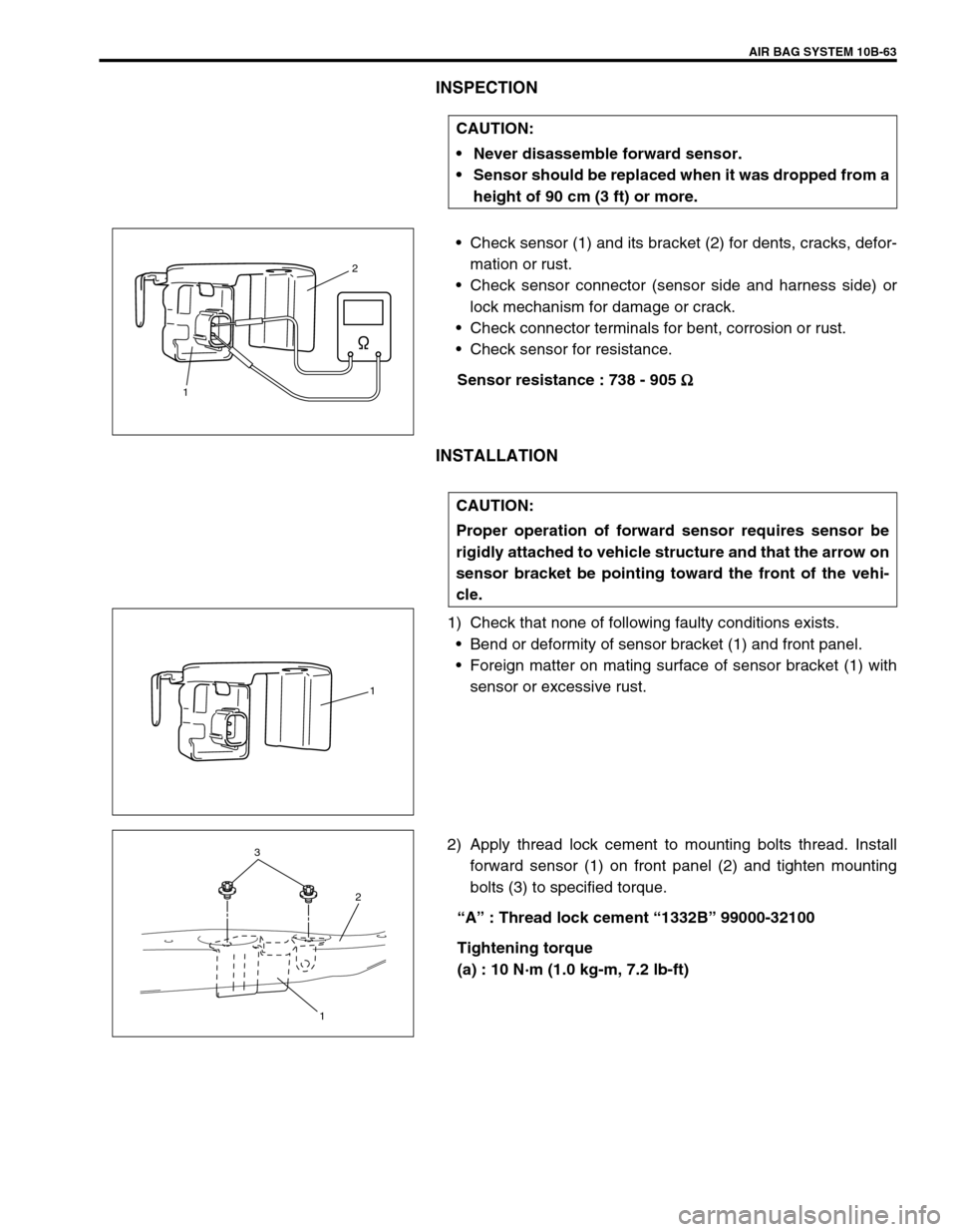
•Check sensor (1) and its bracket (2) for dents, cracks, defor-
mation or rust.
•Check sensor connector (sensor side and harness side) or
lock mechanism for damage or crack.
•Check connector terminals for bent, corrosion or rust.
•Check sensor for resistance.
Sensor resistance : 738 - 905 Ω
ΩΩ Ω
INSTALLATION
1) Check that none of following faulty conditions exists.
•Bend or deformity of sensor bracket (1) and front panel.
•Foreign matter on mating surface of sensor bracket (1) with
sensor or excessive rust.
2) Apply thread lock cement to mounting bolts thread. Install
forward sensor (1) on front panel (2) and tighten mounting
bolts (3) to specified torque.
“A” : Thread lock cement “1332B” 99000-32100
Tightening torque
(a) : 10 N·m (1.0 kg-m, 7.2 lb-ft) CAUTION:
Never disassemble forward sensor.
Sensor should be replaced when it was dropped from a
height of 90 cm (3 ft) or more.
2
1
CAUTION:
Proper operation of forward sensor requires sensor be
rigidly attached to vehicle structure and that the arrow on
sensor bracket be pointing toward the front of the vehi-
cle.
1
3
2
1