Hoses SUZUKI GRAND VITARA 2001 2.G Owners Manual
[x] Cancel search | Manufacturer: SUZUKI, Model Year: 2001, Model line: GRAND VITARA, Model: SUZUKI GRAND VITARA 2001 2.GPages: 656, PDF Size: 14.31 MB
Page 15 of 656
0B-2 MAINTENANCE AND LUBRICATION
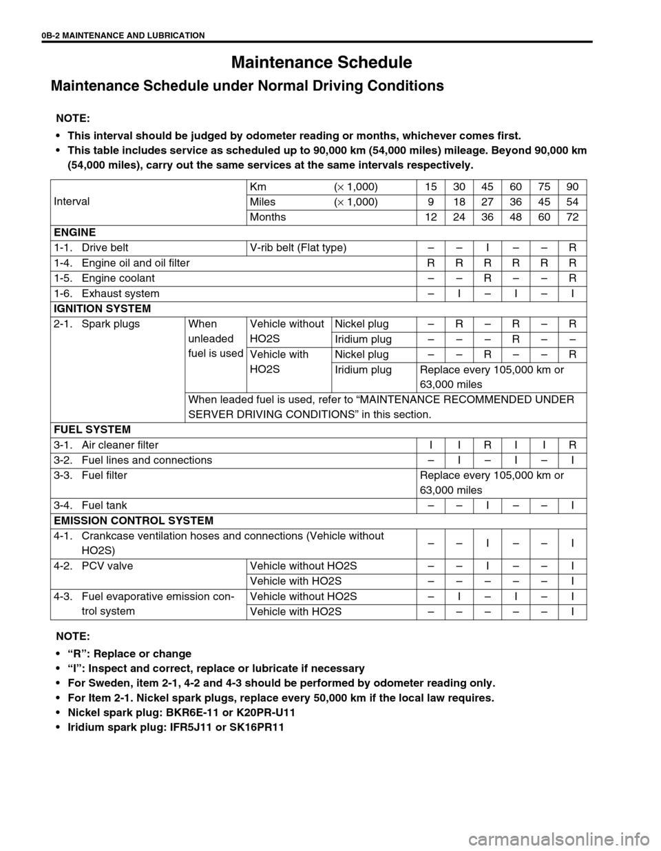
Maintenance Schedule
Maintenance Schedule under Normal Driving Conditions
NOTE:
This interval should be judged by odometer reading or months, whichever comes first.
This table includes service as scheduled up to 90,000 km (54,000 miles) mileage. Beyond 90,000 km
(54,000 miles), carry out the same services at the same intervals respectively.
IntervalKm (× 1,000) 15 30 45 60 75 90
Miles (× 1,000) 9 18 27 36 45 54
Months 12 24 36 48 60 72
ENGINE
1-1. Drive belt V-rib belt (Flat type)––I––R
1-4. Engine oil and oil filter R R R R R R
1-5. Engine coolant––R––R
1-6. Exhaust system–I–I–I
IGNITION SYSTEM
2-1. Spark plugs When
unleaded
fuel is usedVehicle without
HO2SNickel plug –R–R–R
Iridium plug–––R––
Vehicle with
HO2SNickel plug ––R––R
Iridium plug Replace every 105,000 km or
63,000 miles
When leaded fuel is used, refer to “MAINTENANCE RECOMMENDED UNDER
SERVER DRIVING CONDITIONS” in this section.
FUEL SYSTEM
3-1. Air cleaner filter I I R I I R
3-2. Fuel lines and connections–I–I–I
3-3. Fuel filter Replace every 105,000 km or
63,000 miles
3-4. Fuel tank––I––I
EMISSION CONTROL SYSTEM
4-1. Crankcase ventilation hoses and connections (Vehicle without
HO2S)––I––I
4-2. PCV valve Vehicle without HO2S––I––I
Vehicle with HO2S–––––I
4-3. Fuel evaporative emission con-
trol systemVehicle without HO2S–I–I–I
Vehicle with HO2S–––––I
NOTE:
“R”: Replace or change
“I”: Inspect and correct, replace or lubricate if necessary
For Sweden, item 2-1, 4-2 and 4-3 should be performed by odometer reading only.
For Item 2-1. Nickel spark plugs, replace every 50,000 km if the local law requires.
Nickel spark plug: BKR6E-11 or K20PR-U11
Iridium spark plug: IFR5J11 or SK16PR11
Page 16 of 656
MAINTENANCE AND LUBRICATION 0B-3
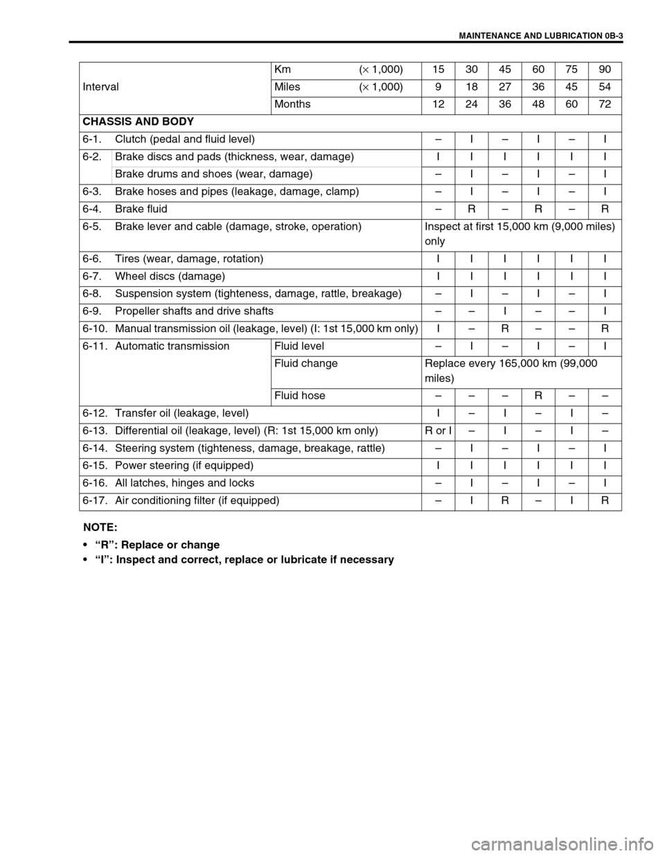
IntervalKm (× 1,000) 153045607590
Miles (× 1,000) 9 18 27 36 45 54
Months 12 24 36 48 60 72
CHASSIS AND BODY
6-1. Clutch (pedal and fluid level)–I–I–I
6-2.Brake discs and pads (thickness, wear, damage) IIIIII
Brake drums and shoes (wear, damage)–I–I–I
6-3. Brake hoses and pipes (leakage, damage, clamp)–I–I–I
6-4. Brake fluid–R–R–R
6-5. Brake lever and cable (damage, stroke, operation) Inspect at first 15,000 km (9,000 miles)
only
6-6.Tires (wear, damage, rotation) IIIIII
6-7.Wheel discs (damage) IIIIII
6-8. Suspension system (tighteness, damage, rattle, breakage)–I–I–I
6-9. Propeller shafts and drive shafts––I––I
6-10. Manual transmission oil (leakage, level) (I: 1st 15,000 km only) I–R––R
6-11. Automatic transmission Fluid level –I–I–I
Fluid change Replace every 165,000 km (99,000
miles)
Fluid hose–––R––
6-12. Transfer oil (leakage, level) I–I–I–
6-13. Differential oil (leakage, level) (R: 1st 15,000 km only) R or I–I–I–
6-14. Steering system (tighteness, damage, breakage, rattle)–I–I–I
6-15.Power steering (if equipped) IIIIII
6-16. All latches, hinges and locks–I–I–I
6-17. Air conditioning filter (if equipped)–IR–IR
NOTE:
“R”: Replace or change
“I”: Inspect and correct, replace or lubricate if necessary
Page 27 of 656
1B-2 AIR CONDITIONING (OPTIONAL)
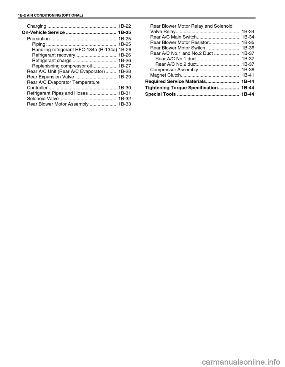
Charging .................................................... 1B-22
On-Vehicle Service ...................................... 1B-25
Precaution .................................................. 1B-25
Piping ..................................................... 1B-25
Handling refrigerant HFC-134a (R-134a) 1B-26
Refrigerant recovery............................... 1B-26
Refrigerant charge ................................. 1B-26
Replenishing compressor oil .................. 1B-27
Rear A/C Unit (Rear A/C Evaporator) ........ 1B-28
Rear Expansion Valve ............................... 1B-29
Rear A/C Evaporator Temperature
Controller ................................................... 1B-30
Refrigerant Pipes and Hoses ..................... 1B-31
Solenoid Valve ........................................... 1B-32
Rear Blower Motor Assembly .................... 1B-33Rear Blower Motor Relay and Solenoid
Valve Relay................................................ 1B-34
Rear A/C Main Switch................................ 1B-34
Rear Blower Motor Resistor....................... 1B-35
Rear Blower Motor Switch ......................... 1B-36
Rear A/C No.1 and No.2 Duct ................... 1B-37
Rear A/C No.1 duct ................................ 1B-37
Rear A/C No.2 duct ................................ 1B-37
Compressor Assembly............................... 1B-38
Magnet Clutch............................................ 1B-41
Required Service Materials ......................... 1B-44
Tightening Torque Specification................ 1B-44
Special Tools ............................................... 1B-44
Page 35 of 656
1B-10 AIR CONDITIONING (OPTIONAL)
Performance Diagnosis
1) Confirm that vehicle and environmental conditions are as fol-
lows.
Vehicle is not exposed to direct sun.
Ambient temperature is within 15 - 35 °C (59 - 95 °F).
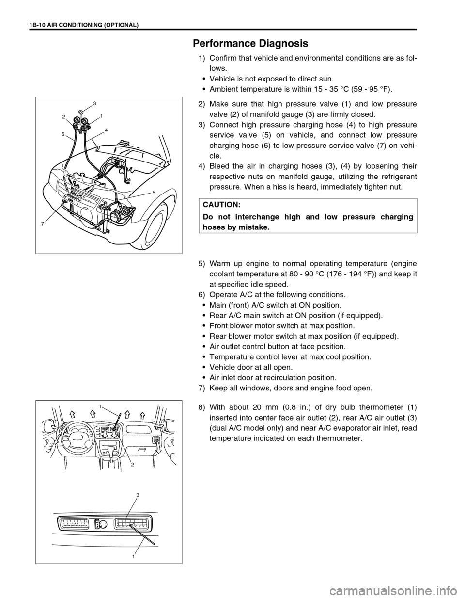
2) Make sure that high pressure valve (1) and low pressure
valve (2) of manifold gauge (3) are firmly closed.
3) Connect high pressure charging hose (4) to high pressure
service valve (5) on vehicle, and connect low pressure
charging hose (6) to low pressure service valve (7) on vehi-
cle.
4) Bleed the air in charging hoses (3), (4) by loosening their
respective nuts on manifold gauge, utilizing the refrigerant
pressure. When a hiss is heard, immediately tighten nut.
5) Warm up engine to normal operating temperature (engine
coolant temperature at 80 - 90 °C (176 - 194 °F)) and keep it
at specified idle speed.
6) Operate A/C at the following conditions.
Main (front) A/C switch at ON position.
Rear A/C main switch at ON position (if equipped).
Front blower motor switch at max position.
Rear blower motor switch at max position (if equipped).
Air outlet control button at face position.
Temperature control lever at max cool position.
Vehicle door at all open.
Air inlet door at recirculation position.
7) Keep all windows, doors and engine food open.
8) With about 20 mm (0.8 in.) of dry bulb thermometer (1)
inserted into center face air outlet (2), rear A/C air outlet (3)
(dual A/C model only) and near A/C evaporator air inlet, read
temperature indicated on each thermometer. CAUTION:
Do not interchange high and low pressure charging
hoses by mistake.
2
64
3
75 1
3
1
2
Page 48 of 656
AIR CONDITIONING (OPTIONAL) 1B-23
The initial charging of the A/C system is performed from the high-
pressure side with the engine stopped.
And next, this method must be followed by charging from the low-
pressure side with the engine running.
1) Check to make sure that hoses are routed properly after
evacuating the system.
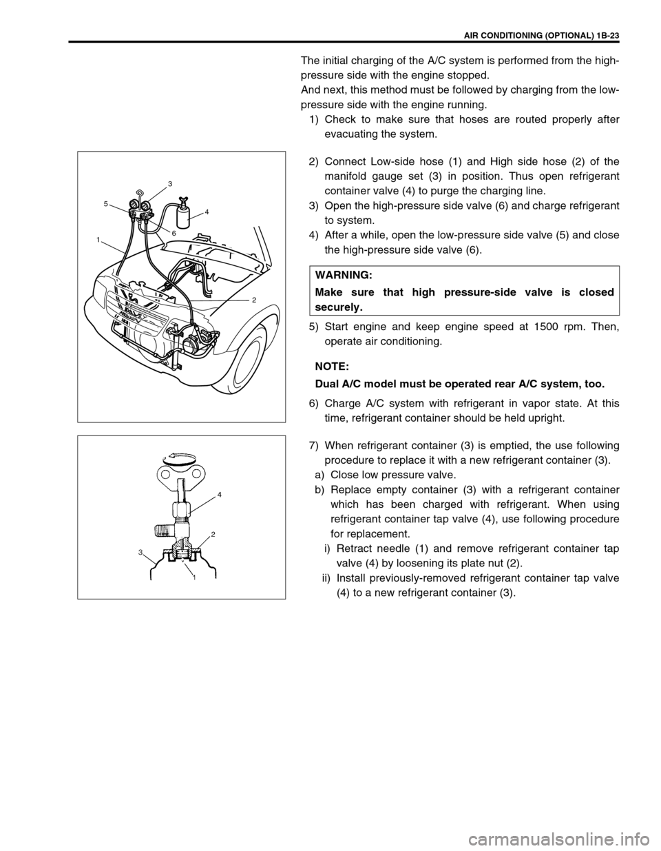
2) Connect Low-side hose (1) and High side hose (2) of the
manifold gauge set (3) in position. Thus open refrigerant
container valve (4) to purge the charging line.
3) Open the high-pressure side valve (6) and charge refrigerant
to system.
4) After a while, open the low-pressure side valve (5) and close
the high-pressure side valve (6).
5) Start engine and keep engine speed at 1500 rpm. Then,
operate air conditioning.
6) Charge A/C system with refrigerant in vapor state. At this
time, refrigerant container should be held upright.
7) When refrigerant container (3) is emptied, the use following
procedure to replace it with a new refrigerant container (3).
a) Close low pressure valve.
b) Replace empty container (3) with a refrigerant container
which has been charged with refrigerant. When using
refrigerant container tap valve (4), use following procedure
for replacement.
i) Retract needle (1) and remove refrigerant container tap
valve (4) by loosening its plate nut (2).
ii) Install previously-removed refrigerant container tap valve
(4) to a new refrigerant container (3). WARNING:
Make sure that high pressure-side valve is closed
securely.
NOTE:
Dual A/C model must be operated rear A/C system, too.
153
64
2
Page 50 of 656
AIR CONDITIONING (OPTIONAL) 1B-25
On-Vehicle Service
Precaution
When servicing air conditioning system, the following rules must be observed.
Piping
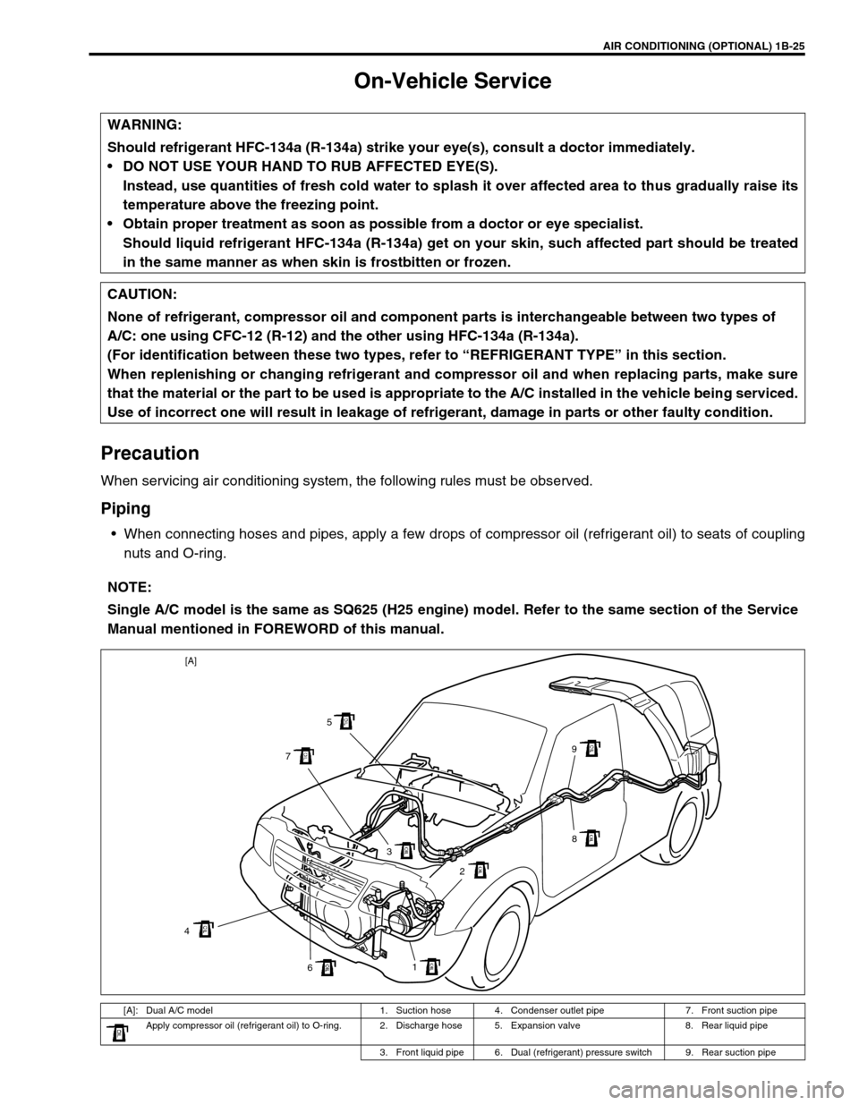
When connecting hoses and pipes, apply a few drops of compressor oil (refrigerant oil) to seats of coupling
nuts and O-ring. WARNING:
Should refrigerant HFC-134a (R-134a) strike your eye(s), consult a doctor immediately.
DO NOT USE YOUR HAND TO RUB AFFECTED EYE(S).
Instead, use quantities of fresh cold water to splash it over affected area to thus gradually raise its
temperature above the freezing point.
Obtain proper treatment as soon as possible from a doctor or eye specialist.
Should liquid refrigerant HFC-134a (R-134a) get on your skin, such affected part should be treated
in the same manner as when skin is frostbitten or frozen.
CAUTION:
None of refrigerant, compressor oil and component parts is interchangeable between two types of
A/C: one using CFC-12 (R-12) and the other using HFC-134a (R-134a).
(For identification between these two types, refer to “REFRIGERANT TYPE” in this section.
When replenishing or changing refrigerant and compressor oil and when replacing parts, make sure
that the material or the part to be used is appropriate to the A/C installed in the vehicle being serviced.
Use of incorrect one will result in leakage of refrigerant, damage in parts or other faulty condition.
NOTE:
Single A/C model is the same as SQ625 (H25 engine) model. Refer to the same section of the Service
Manual mentioned in FOREWORD of this manual.
[A]: Dual A/C model 1. Suction hose 4. Condenser outlet pipe 7. Front suction pipe
Apply compressor oil (refrigerant oil) to O-ring. 2. Discharge hose 5. Expansion valve 8. Rear liquid pipe
3. Front liquid pipe 6. Dual (refrigerant) pressure switch 9. Rear suction pipe
1
6 43 75
9
8
2 [A]
Page 52 of 656
AIR CONDITIONING (OPTIONAL) 1B-27
Replenishing compressor oil
When replacing air conditioning parts with new ones, it is neces-
sary to replenish oil by the amount supposedly remaining in each
part.
WHEN CHANGING GAS ONLY
When it is unavoidable to change gas without replacing any com-
ponent part for engine removal and installation or for some other
reason, replenish 20 cm
3 (20cc) oil. When replenishing gas only,
oil replenishment is not necessary.
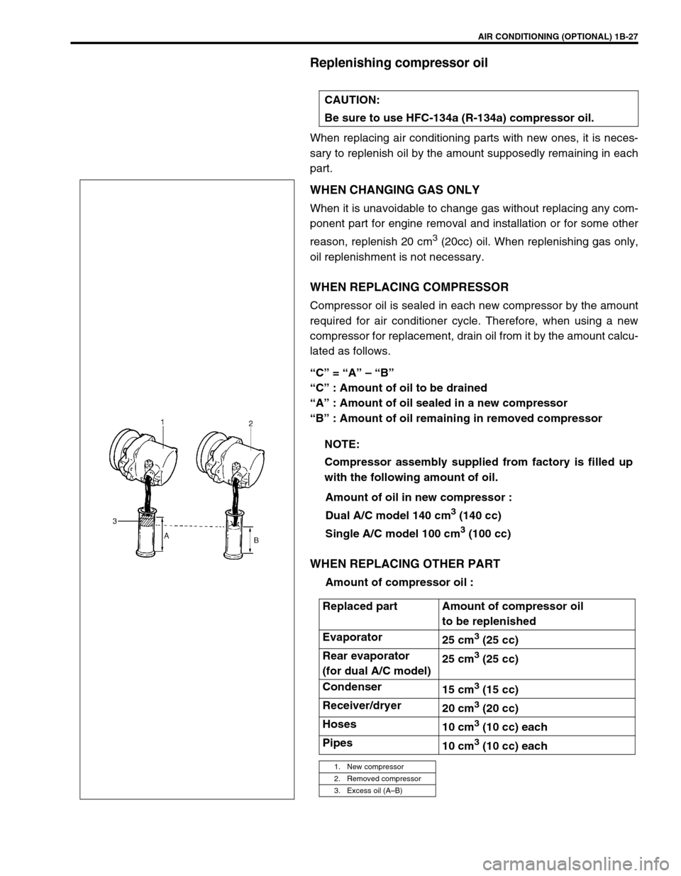
WHEN REPLACING COMPRESSOR
Compressor oil is sealed in each new compressor by the amount
required for air conditioner cycle. Therefore, when using a new
compressor for replacement, drain oil from it by the amount calcu-
lated as follows.
“C” = “A” – “B”
“C” : Amount of oil to be drained
“A” : Amount of oil sealed in a new compressor
“B” : Amount of oil remaining in removed compressor
Amount of oil in new compressor :
Dual A/C model 140 cm
3 (140 cc)
Single A/C model 100 cm
3 (100 cc)
WHEN REPLACING OTHER PART
Amount of compressor oil : CAUTION:
Be sure to use HFC-134a (R-134a) compressor oil.
NOTE:
Compressor assembly supplied from factory is filled up
with the following amount of oil.
Replaced part Amount of compressor oil
to be replenished
Evaporator
25 cm
3 (25 cc)
Rear evaporator
(for dual A/C model)25 cm
3 (25 cc)
Condenser
15 cm
3 (15 cc)
Receiver/dryer
20 cm
3 (20 cc)
Hoses
10 cm
3 (10 cc) each
Pipes
10 cm
3 (10 cc) each
1. New compressor
2. Removed compressor
3. Excess oil (A–B)
Page 56 of 656
AIR CONDITIONING (OPTIONAL) 1B-31
INSPECTION
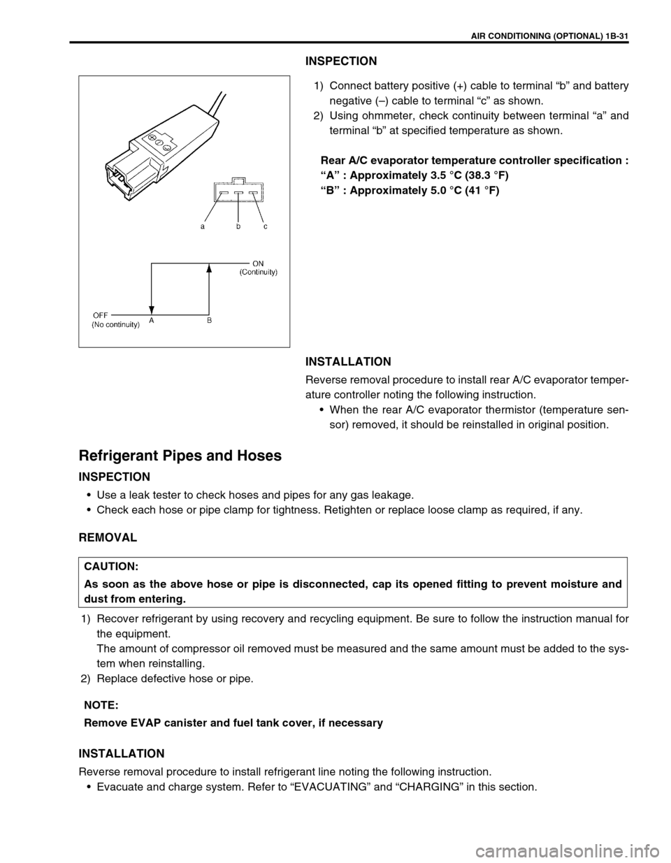
1) Connect battery positive (+) cable to terminal “b” and battery
negative (–) cable to terminal “c” as shown.
2) Using ohmmeter, check continuity between terminal “a” and
terminal “b” at specified temperature as shown.
Rear A/C evaporator temperature controller specification :
“A” : Approximately 3.5 °C (38.3 °F)
“B” : Approximately 5.0 °C (41 °F)
INSTALLATION
Reverse removal procedure to install rear A/C evaporator temper-
ature controller noting the following instruction.
When the rear A/C evaporator thermistor (temperature sen-
sor) removed, it should be reinstalled in original position.
Refrigerant Pipes and Hoses
INSPECTION
Use a leak tester to check hoses and pipes for any gas leakage.
Check each hose or pipe clamp for tightness. Retighten or replace loose clamp as required, if any.
REMOVAL
1) Recover refrigerant by using recovery and recycling equipment. Be sure to follow the instruction manual for
the equipment.
The amount of compressor oil removed must be measured and the same amount must be added to the sys-
tem when reinstalling.
2) Replace defective hose or pipe.
INSTALLATION
Reverse removal procedure to install refrigerant line noting the following instruction.
Evacuate and charge system. Refer to “EVACUATING” and “CHARGING” in this section.
CAUTION:
As soon as the above hose or pipe is disconnected, cap its opened fitting to prevent moisture and
dust from entering.
NOTE:
Remove EVAP canister and fuel tank cover, if necessary
Page 174 of 656
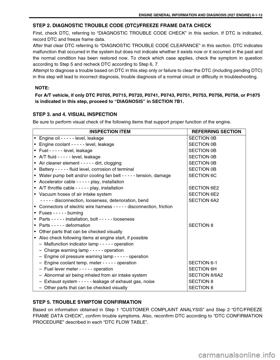
ENGINE GENERAL INFORMATION AND DIAGNOSIS (H27 ENGINE) 6-1-13
STEP 2. DIAGNOSTIC TROUBLE CODE (DTC)/FREEZE FRAME DATA CHECK
First, check DTC, referring to “DIAGNOSTIC TROUBLE CODE CHECK” in this section. If DTC is indicated,
record DTC and freeze frame data.
After that clear DTC referring to “DIAGNOSTIC TROUBLE CODE CLEARANCE” in this section. DTC indicates
malfunction that occurred in the system but does not indicate whether it exists now or it occurred in the past and
the normal condition has been restored now. To check which case applies, check the symptom in question
according to Step 5 and recheck DTC according to Step 6, 7.
Attempt to diagnose a trouble based on DTC in this step only or failure to clear the DTC (including pending DTC)
in this step will lead to incorrect diagnosis, trouble diagnosis of a normal circuit or difficulty in troubleshooting.
STEP 3. and 4. VISUAL INSPECTION
Be sure to perform visual check of the following items that support proper function of the engine.
STEP 5. TROUBLE SYMPTOM CONFIRMATION
Based on information obtained in Step 1 “CUSTOMER COMPLAINT ANALYSIS” and Step 2 “DTC/FREEZE
FRAME DATA CHECK”, confirm trouble symptoms. Also, reconfirm DTC according to “DTC CONFIRMATION
PROCEDURE” described in each “DTC FLOW TABLE”.NOTE:
For A/T vehicle, if only DTC P0705, P0715, P0720, P0741, P0743, P0751, P0753, P0756, P0758, or P1875
is indicated in this step, proceed to “DIAGNOSIS” in SECTION 7B1.
INSPECTION ITEM REFERRING SECTION
• Engine oil - - - - - level, leakage
• Engine coolant - - - - - level, leakage
• Fuel - - - - - level, leakage
• A/T fluid - - - - - level, leakage
• Air cleaner element - - - - - dirt, clogging
• Battery - - - - - fluid level, corrosion of terminal
• Water pump belt and/or cooling fan belt - - - - - tension, damage
• Accelerator cable - - - - - play, installation
• A/T throttle cable - - - - - play, installation
• Vacuum hoses of air intake system
- - - - - disconnection, looseness, deterioration, bend
• Connectors of electric wire harness - - - - - disconnection, friction
• Fuses - - - - - burning
• Parts - - - - - installation, bolt - - - - - looseness
• Parts - - - - - deformation
• Other parts that can be checked visually
• Also check following items at engine start, if possible
– Malfunction indicator lamp - - - - - operation
– Charge warning lamp - - - - - operation
– Engine oil pressure warning lamp - - - - - operation
– Engine coolant temp. meter - - - - - operation
– Fuel lever meter - - - - - operation
– Abnormal air being inhaled from air intake system
– Exhaust system - - - - - leakage of exhaust gas, noise
– Other parts that can be checked visuallySECTION 0B
SECTION 0B
SECTION 0B
SECTION 0B
SECTION 0B
SECTION 0B
SECTION 6C
SECTION 6E2
SECTION 6E2
SECTION 6A2
SECTION 8
SECTION 6-1
SECTION 6H
SECTION 8/6A2
SECTION 8
SECTION 8
Page 262 of 656
ENGINE GENERAL INFORMATION AND DIAGNOSIS (H27 ENGINE) 6-1-101
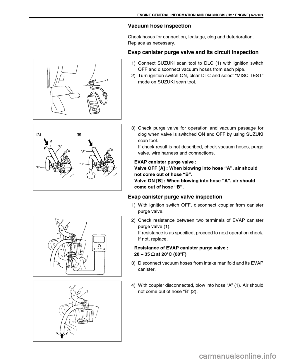
Vacuum hose inspection
Check hoses for connection, leakage, clog and deterioration.
Replace as necessary.
Evap canister purge valve and its circuit inspection
1) Connect SUZUKI scan tool to DLC (1) with ignition switch
OFF and disconnect vacuum hoses from each pipe.
2) Turn ignition switch ON, clear DTC and select “MISC TEST”
mode on SUZUKI scan tool.
3) Check purge valve for operation and vacuum passage for
clog when valve is switched ON and OFF by using SUZUKI
scan tool.
If check result is not described, check vacuum hoses, purge
valve, wire harness and connections.
EVAP canister purge valve :
Valve OFF [A] : When blowing into hose “A”, air should
not come out of hose “B”.
Valve ON [B] : When blowing into hose “A”, air should
come out of hose “B”.
Evap canister purge valve inspection
1) With ignition switch OFF, disconnect coupler from canister
purge valve.
2) Check resistance between two terminals of EVAP canister
purge valve (1).
If resistance is as specified, proceed to next operation check.
If not, replace.
Resistance of EVAP canister purge valve :
28 – 35
Ω
ΩΩ Ω at 20°C (68°F)
3) Disconnect vacuum hoses from intake manifold and its EVAP
canister.
4) With coupler disconnected, blow into hose “A” (1). Air should
not come out of hose “B” (2).