oil pressure switch SUZUKI GRAND VITARA 2001 2.G Owners Manual
[x] Cancel search | Manufacturer: SUZUKI, Model Year: 2001, Model line: GRAND VITARA, Model: SUZUKI GRAND VITARA 2001 2.GPages: 656, PDF Size: 14.31 MB
Page 26 of 656
AIR CONDITIONING (OPTIONAL) 1B-1
1B
SECTION 1B
AIR CONDITIONING (OPTIONAL)
CONTENTS
General Description ....................................... 1B-3
Refrigerant Type .......................................... 1B-3
Refrigerant Flow of Air Conditioning System 1B-3
Major Components And Location ................. 1B-4
Diagnosis ........................................................ 1B-6
General ........................................................ 1B-6
Main A/C system (front A/C system) ........ 1B-6
Rear A/C system ...................................... 1B-8
Quickly Checking of Refrigerant Charge
(If Equipped with Sight Glass) ...................... 1B-9
Performance Diagnosis .............................. 1B-10
Performance diagnosis table .................. 1B-12
Detail diagnosis table (at ambient temperature within 30 - 35 °C
(85 - 95 °F)) ............................................ 1B-13
Wiring Circuit.............................................. 1B-14
Inspection of A/C Controller and Its
Circuits ....................................................... 1B-15
Voltage check......................................... 1B-15
Refrigerant Recovery, Evacuation and
Charging ....................................................... 1B-19
Operation Procedure for Charging A/C with
Refrigerant ................................................. 1B-19
Recovery .................................................... 1B-20
Evacuating ................................................. 1B-21
Evacuating procedure ............................ 1B-21
Checking system for pressure leaks ...... 1B-22 WARNING:
For vehicles equipped with Supplemental Restraint (Air Bag) System:
Service on and around the air bag system components or wiring must be performed only by an
authorized SUZUKI dealer. Refer to “Air Bag System Components and Wiring Location View” under
“General Description” in air bag system section in order to confirm whether you are performing ser-
vice on or near the air bag system components or wiring. Please observe all WARNINGS and “Ser-
vice Precautions” under “On-Vehicle Service” in air bag system section before performing service
on or around the air bag system components or wiring. Failure to follow WARNINGS could result in
unintentional activation of the system or could render the system inoperative. Either of these two
conditions may result in severe injury.
Technical service work must be started at least 90 seconds after the ignition switch is turned to the
“LOCK” position and the negative cable is disconnected from the battery. Otherwise, the system
may be activated by reserve energy in the Sensing and Diagnostic Module (SDM).
CAUTION:
The air conditioning system of this vehicle uses refrigerant HFC-134a (R-134a).
None of refrigerant, compressor oil and component parts is interchangeable between two types of
A/C: one using refrigerant CFC-12 (R-12) and the other using refrigerant HFC-134a (R-134a).
Be sure to check which refrigerant is used before any service work including inspection and mainte-
nance. For identification between these two types, refer to “REFRIGERANT TYPE” in this section.
When replenishing or changing refrigerant and compressor oil and when replacing parts, make sure
that the material or the part to be used is appropriate to the A/C installed in the vehicle being serviced.
Use of incorrect one will result in leakage of refrigerant, damage in parts or other faulty condition.
NOTE:
For the descriptions (items) not found in this section, refer to the same section of the Service Man-
ual mentioned in FOREWORD of this manual.
For basic servicing method of the air conditioning system that is not described in this section, refer
to “AIR CONDITIONING BASIC MANUAL (99520-02130)”.
Page 37 of 656
1B-12 AIR CONDITIONING (OPTIONAL)
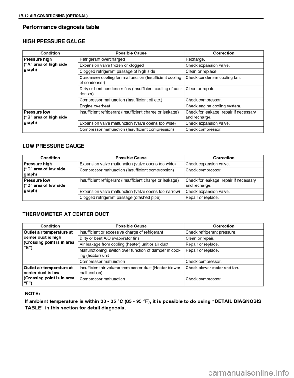
Performance diagnosis table
HIGH PRESSURE GAUGE
LOW PRESSURE GAUGE
THERMOMETER AT CENTER DUCT
Condition Possible Cause Correction
Pressure high
(“A” area of high side
graph)Refrigerant overcharged Recharge.
Expansion valve frozen or clogged Check expansion valve.
Clogged refrigerant passage of high side Clean or replace.
Condenser cooling fan malfunction (Insufficient cooling
of condenser)Check condenser cooling fan.
Dirty or bent condenser fins (Insufficient cooling of con-
denser)Clean or repair.
Compressor malfunction (Insufficient oil etc.) Check compressor.
Engine overheat Check engine cooling system.
Pressure low
(“B” area of high side
graph)Insufficient refrigerant (Insufficient charge or leakage) Check for leakage, repair if necessary
and recharge.
Expansion valve malfunction (valve opens too wide) Check expansion valve.
Compressor malfunction (Insufficient compression) Check compressor.
Condition Possible Cause Correction
Pressure high
(“C” area of low side
graph)Expansion valve malfunction (valve opens too wide) Check expansion valve.
Compressor malfunction (Insufficient compression) Check compressor.
Pressure low
(“D” area of low side
graph)Insufficient refrigerant (Insufficient charge or leakage) Check for leakage, repair if necessary
and recharge.
Expansion valve malfunction (valve opens too narrow) Check expansion valve.
Clogged refrigerant passage (crashed pipe) Repair or replace.
Condition Possible Cause Correction
Outlet air temperature at
center duct is high
(Crossing point is in area
“E”)Insufficient or excessive charge of refrigerant Check refrigerant pressure.
Dirty or bent A/C evaporator fins Clean or repair.
Air leakage from cooling (heater) unit or air duct Repair or replace.
Malfunctioning, switch over function of damper in cool-
ing (heater) unitRepair or replace.
Compressor malfunction Check compressor.
Outlet air temperature at
center duct is low
(Crossing point is in area
“F”)Insufficient air volume from center duct (Heater blower
malfunction)Check blower motor and fan.
Compressor malfunction Check compressor.
NOTE:
If ambient temperature is within 30 - 35 °C (85 - 95 °F), it is possible to do using “DETAIL DIAGNOSIS
TABLE” in this section for detail diagnosis.
Page 50 of 656
AIR CONDITIONING (OPTIONAL) 1B-25
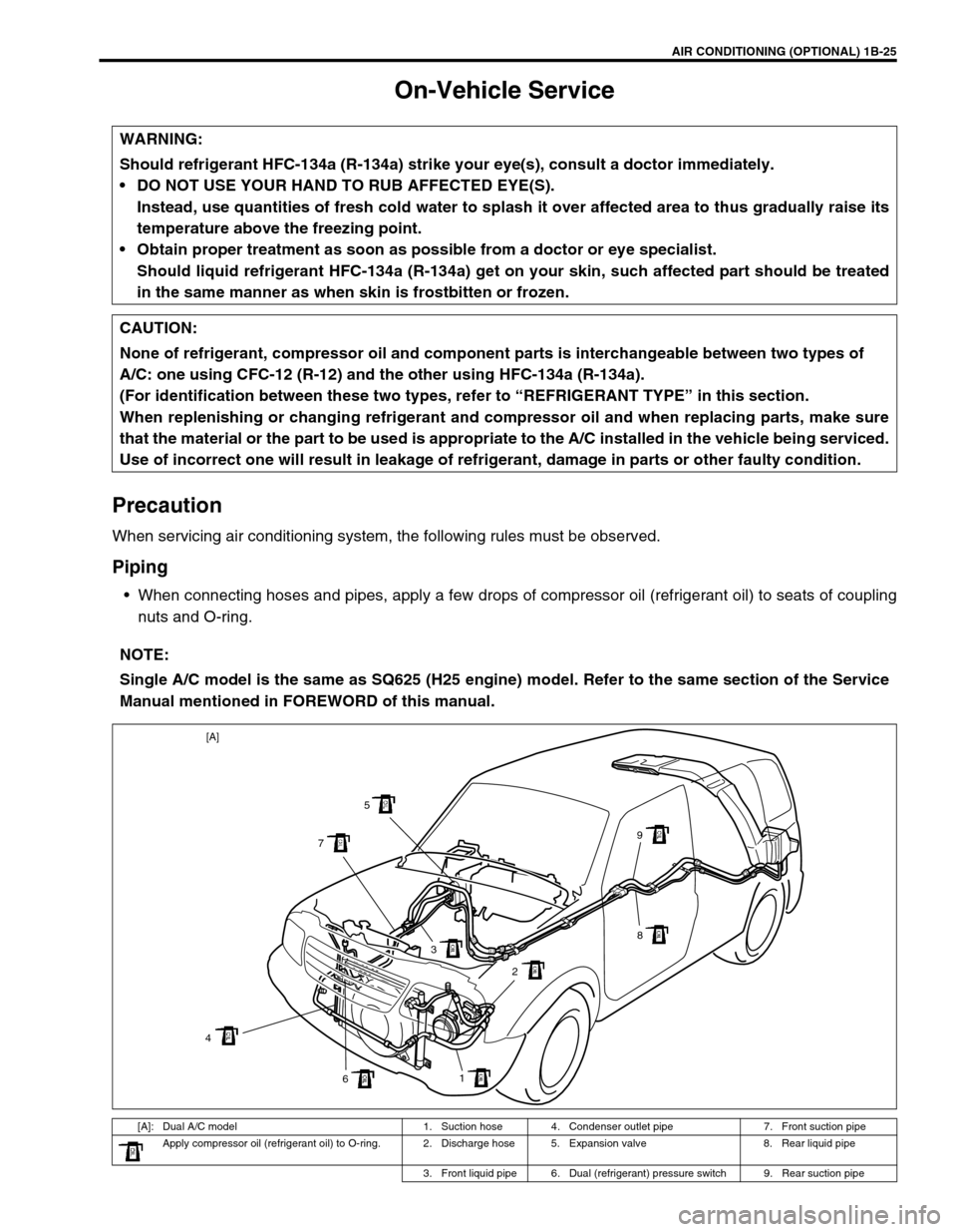
On-Vehicle Service
Precaution
When servicing air conditioning system, the following rules must be observed.
Piping
When connecting hoses and pipes, apply a few drops of compressor oil (refrigerant oil) to seats of coupling
nuts and O-ring. WARNING:
Should refrigerant HFC-134a (R-134a) strike your eye(s), consult a doctor immediately.
DO NOT USE YOUR HAND TO RUB AFFECTED EYE(S).
Instead, use quantities of fresh cold water to splash it over affected area to thus gradually raise its
temperature above the freezing point.
Obtain proper treatment as soon as possible from a doctor or eye specialist.
Should liquid refrigerant HFC-134a (R-134a) get on your skin, such affected part should be treated
in the same manner as when skin is frostbitten or frozen.
CAUTION:
None of refrigerant, compressor oil and component parts is interchangeable between two types of
A/C: one using CFC-12 (R-12) and the other using HFC-134a (R-134a).
(For identification between these two types, refer to “REFRIGERANT TYPE” in this section.
When replenishing or changing refrigerant and compressor oil and when replacing parts, make sure
that the material or the part to be used is appropriate to the A/C installed in the vehicle being serviced.
Use of incorrect one will result in leakage of refrigerant, damage in parts or other faulty condition.
NOTE:
Single A/C model is the same as SQ625 (H25 engine) model. Refer to the same section of the Service
Manual mentioned in FOREWORD of this manual.
[A]: Dual A/C model 1. Suction hose 4. Condenser outlet pipe 7. Front suction pipe
Apply compressor oil (refrigerant oil) to O-ring. 2. Discharge hose 5. Expansion valve 8. Rear liquid pipe
3. Front liquid pipe 6. Dual (refrigerant) pressure switch 9. Rear suction pipe
1
6 43 75
9
8
2 [A]
Page 195 of 656
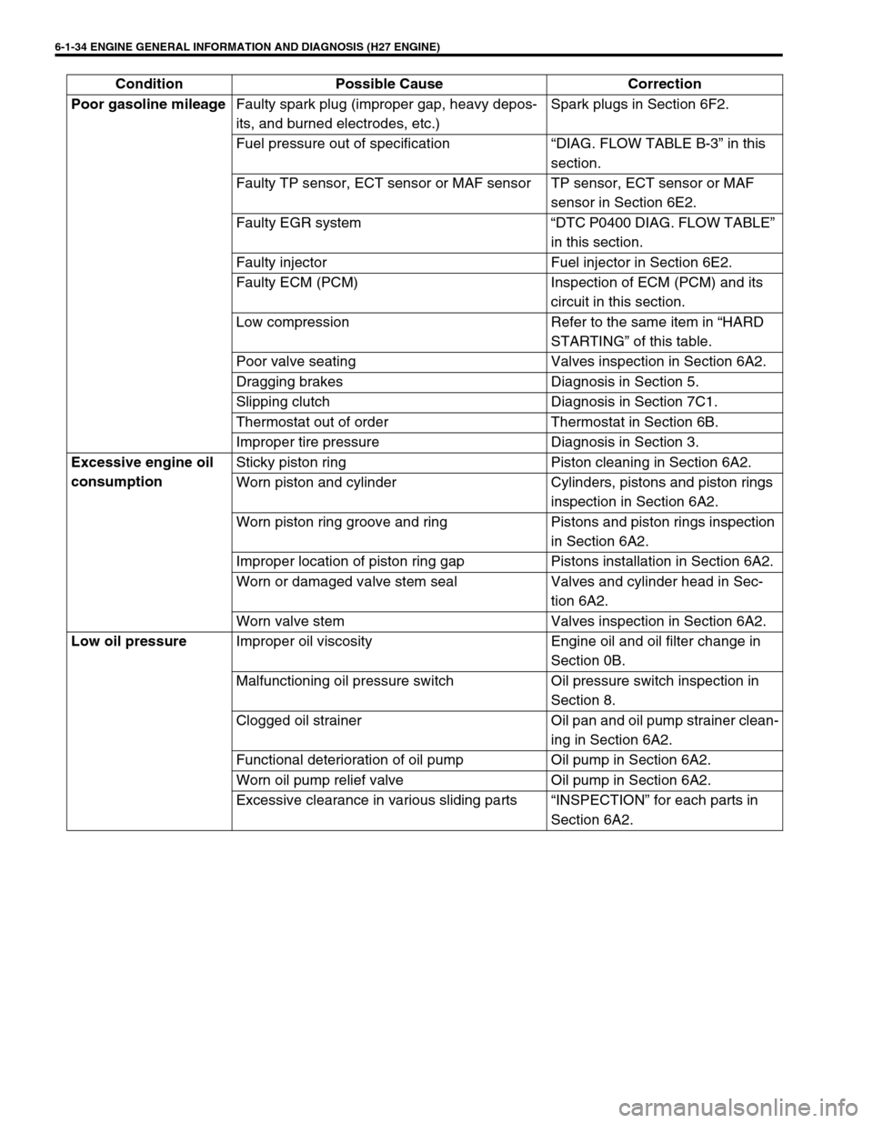
6-1-34 ENGINE GENERAL INFORMATION AND DIAGNOSIS (H27 ENGINE)
Poor gasoline mileage
Faulty spark plug (improper gap, heavy depos-
its, and burned electrodes, etc.)Spark plugs in Section 6F2.
Fuel pressure out of specification “DIAG. FLOW TABLE B-3” in this
section.
Faulty TP sensor, ECT sensor or MAF sensor TP sensor, ECT sensor or MAF
sensor in Section 6E2.
Faulty EGR system “DTC P0400 DIAG. FLOW TABLE”
in this section.
Faulty injector Fuel injector in Section 6E2.
Faulty ECM (PCM) Inspection of ECM (PCM) and its
circuit in this section.
Low compression Refer to the same item in “HARD
STARTING” of this table.
Poor valve seating Valves inspection in Section 6A2.
Dragging brakes Diagnosis in Section 5.
Slipping clutch Diagnosis in Section 7C1.
Thermostat out of order Thermostat in Section 6B.
Improper tire pressure Diagnosis in Section 3.
Excessive engine oil
consumptionSticky piston ring Piston cleaning in Section 6A2.
Worn piston and cylinder Cylinders, pistons and piston rings
inspection in Section 6A2.
Worn piston ring groove and ring Pistons and piston rings inspection
in Section 6A2.
Improper location of piston ring gap Pistons installation in Section 6A2.
Worn or damaged valve stem seal Valves and cylinder head in Sec-
tion 6A2.
Worn valve stem Valves inspection in Section 6A2.
Low oil pressure
Improper oil viscosity Engine oil and oil filter change in
Section 0B.
Malfunctioning oil pressure switch Oil pressure switch inspection in
Section 8.
Clogged oil strainer Oil pan and oil pump strainer clean-
ing in Section 6A2.
Functional deterioration of oil pump Oil pump in Section 6A2.
Worn oil pump relief valve Oil pump in Section 6A2.
Excessive clearance in various sliding parts “INSPECTION” for each parts in
Section 6A2. Condition Possible Cause Correction
Page 200 of 656
ENGINE GENERAL INFORMATION AND DIAGNOSIS (H27 ENGINE) 6-1-39
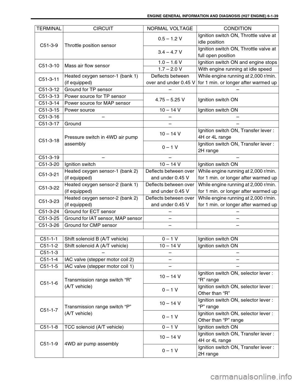
C51-3-9 Throttle position sensor0.5 – 1.2 VIgnition switch ON, Throttle valve at
idle position
3.4 – 4.7 VIgnition switch ON, Throttle valve at
full open position
C51-3-10 Mass air flow sensor1.0 – 1.6 V Ignition switch ON and engine stops
1.7 – 2.0 V With engine running at idle speed
C51-3-11Heated oxygen sensor-1 (bank 1)
(if equipped)Deflects between
over and under 0.45 VWhile engine running at 2,000 r/min.
for 1 min. or longer after warmed up
C51-3-12 Ground for TP sensor – –
C51-3-13 Power source for TP sensor
4.75 – 5.25 V Ignition switch ON
C51-3-14 Power source for MAP sensor
C51-3-15 Power source 10 – 14 V Ignition switch ON
C51-3-16 – – –
C51-3-17 Ground – –
C51-3-18Pressure switch in 4WD air pump
assembly10 – 14 VIgnition switch ON, Transfer lever :
4H or 4L range
0 – 1 VIgnition switch ON, Transfer lever :
2H range
C51-3-19 – – –
C51-3-20 Ignition switch 10 – 14 V Ignition switch ON
C51-3-21Heated oxygen sensor-1 (bank 2)
(if equipped)Deflects between over
and under 0.45 VWhile engine running at 2,000 r/min.
for 1 min. or longer after warmed up
C51-3-22Heated oxygen sensor-2 (bank 1)
(if equipped)Deflects between over
and under 0.45 VWhile engine running at 2,000 r/min.
for 1 min. or longer after warmed up
C51-3-23Heated oxygen sensor-2 (bank 2)
(if equipped)Deflects between over
and under 0.45 VWhile engine running at 2,000 r/min.
for 1 min. or longer after warmed up
C51-3-24 Ground for ECT sensor – –
C51-3-25 Ground for IAT sensor, MAP sensor – –
C51-3-26 Ground for CMP sensor – –
C51-1-1 Shift solenoid B (A/T vehicle) 0 – 1 V Ignition switch ON
C51-1-2 Shift solenoid A (A/T vehicle) 10 – 14 V Ignition switch ON
C51-1-3 – – –
C51-1-4 IAC valve (stepper motor coil 2) – –
C51-1-5 IAC valve (stepper motor coil 1) – –
C51-1-6Transmission range switch “R”
(A/T vehicle)10 – 14 VIgnition switch ON, selector lever :
“R” range
0 – 1 VIgnition switch ON, selector lever :
Other than “R”
C51-1-7Transmission range switch “P”
(A/T vehicle)10 – 14 VIgnition switch ON, selector lever :
“P” range
0 – 1 VIgnition switch ON, selector lever :
Other than “P” range
C51-1-8 TCC solenoid (A/T vehicle) 0 – 1 V Ignition switch ON
C51-1-9 4WD air pump assembly10 – 14 VIgnition switch ON, Transfer lever :
4H or 4L range
0 – 1 VIgnition switch ON, Transfer lever :
2H range TERMINAL CIRCUIT NORMAL VOLTAGE CONDITION
Page 201 of 656
6-1-40 ENGINE GENERAL INFORMATION AND DIAGNOSIS (H27 ENGINE)
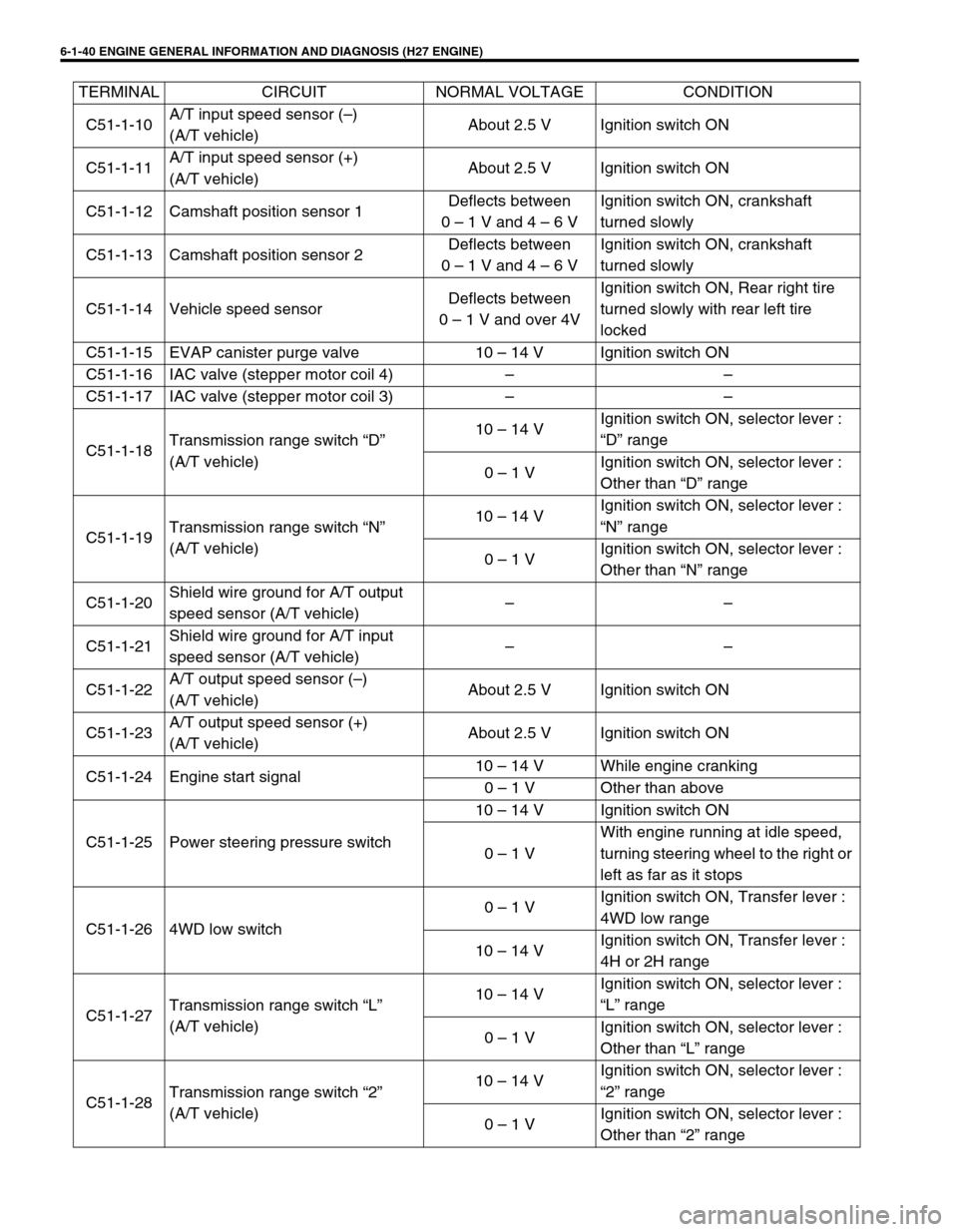
C51-1-10A/T input speed sensor (–)
(A/T vehicle)About 2.5 V Ignition switch ON
C51-1-11A/T input speed sensor (+)
(A/T vehicle)About 2.5 V Ignition switch ON
C51-1-12 Camshaft position sensor 1Deflects between
0 – 1 V and 4 – 6 VIgnition switch ON, crankshaft
turned slowly
C51-1-13 Camshaft position sensor 2Deflects between
0 – 1 V and 4 – 6 VIgnition switch ON, crankshaft
turned slowly
C51-1-14 Vehicle speed sensorDeflects between
0 – 1 V and over 4VIgnition switch ON, Rear right tire
turned slowly with rear left tire
locked
C51-1-15 EVAP canister purge valve 10 – 14 V Ignition switch ON
C51-1-16 IAC valve (stepper motor coil 4) – –
C51-1-17 IAC valve (stepper motor coil 3) – –
C51-1-18Transmission range switch “D”
(A/T vehicle)10 – 14 VIgnition switch ON, selector lever :
“D” range
0 – 1 VIgnition switch ON, selector lever :
Other than “D” range
C51-1-19Transmission range switch “N”
(A/T vehicle)10 – 14 VIgnition switch ON, selector lever :
“N” range
0 – 1 VIgnition switch ON, selector lever :
Other than “N” range
C51-1-20Shield wire ground for A/T output
speed sensor (A/T vehicle)––
C51-1-21Shield wire ground for A/T input
speed sensor (A/T vehicle)––
C51-1-22A/T output speed sensor (–)
(A/T vehicle)About 2.5 V Ignition switch ON
C51-1-23A/T output speed sensor (+)
(A/T vehicle)About 2.5 V Ignition switch ON
C51-1-24 Engine start signal10 – 14 V While engine cranking
0 – 1 V Other than above
C51-1-25 Power steering pressure switch10 – 14 V Ignition switch ON
0 – 1 VWith engine running at idle speed,
turning steering wheel to the right or
left as far as it stops
C51-1-26 4WD low switch0 – 1 VIgnition switch ON, Transfer lever :
4WD low range
10 – 14 VIgnition switch ON, Transfer lever :
4H or 2H range
C51-1-27Transmission range switch “L”
(A/T vehicle)10 – 14 VIgnition switch ON, selector lever :
“L” range
0 – 1 VIgnition switch ON, selector lever :
Other than “L” range
C51-1-28Transmission range switch “2”
(A/T vehicle)10 – 14 VIgnition switch ON, selector lever :
“2” range
0 – 1 VIgnition switch ON, selector lever :
Other than “2” range TERMINAL CIRCUIT NORMAL VOLTAGE CONDITION
Page 338 of 656
ENGINE AND EMISSION CONTROL SYSTEM (SEQUENTIAL MULTIPORT FUEL INJECTION FOR H27 ENGINE) 6E2-5
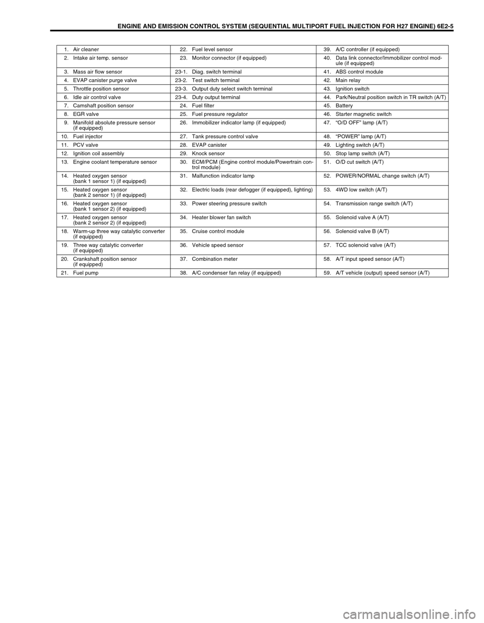
1. Air cleaner 22. Fuel level sensor 39. A/C controller (if equipped)
2. Intake air temp. sensor 23. Monitor connector (if equipped) 40. Data link connector/Immobilizer control mod-
ule (if equipped)
3. Mass air flow sensor 23-1. Diag. switch terminal 41. ABS control module
4. EVAP canister purge valve 23-2. Test switch terminal 42. Main relay
5. Throttle position sensor 23-3. Output duty select switch terminal 43. Ignition switch
6. Idle air control valve 23-4. Duty output terminal 44. Park/Neutral position switch in TR switch (A/T)
7. Camshaft position sensor 24. Fuel filter 45. Battery
8. EGR valve 25. Fuel pressure regulator 46. Starter magnetic switch
9. Manifold absolute pressure sensor
(if equipped)26. Immobilizer indicator lamp (if equipped) 47.“O/D OFF” lamp (A/T)
10. Fuel injector 27. Tank pressure control valve 48.“POWER” lamp (A/T)
11. PCV valve 28. EVAP canister 49. Lighting switch (A/T)
12. Ignition coil assembly 29. Knock sensor 50. Stop lamp switch (A/T)
13. Engine coolant temperature sensor 30. ECM/PCM (Engine control module/Powertrain con-
trol module)51. O/D cut switch (A/T)
14. Heated oxygen sensor
(bank 1 sensor 1) (if equipped)31. Malfunction indicator lamp 52. POWER/NORMAL change switch (A/T)
15. Heated oxygen sensor
(bank 2 sensor 1) (if equipped)32. Electric loads (rear defogger (if equipped), lighting) 53. 4WD low switch (A/T)
16. Heated oxygen sensor
(bank 1 sensor 2) (if equipped)33. Power steering pressure switch 54. Transmission range switch (A/T)
17. Heated oxygen sensor
(bank 2 sensor 2) (if equipped)34. Heater blower fan switch 55. Solenoid valve A (A/T)
18. Warm-up three way catalytic converter
(if equipped)35. Cruise control module 56. Solenoid valve B (A/T)
19. Three way catalytic converter
(if equipped)36. Vehicle speed sensor 57. TCC solenoid valve (A/T)
20. Crankshaft position sensor
(if equipped)37. Combination meter 58. A/T input speed sensor (A/T)
21. Fuel pump 38. A/C condenser fan relay (if equipped) 59. A/T vehicle (output) speed sensor (A/T)
Page 341 of 656
6E2-8 ENGINE AND EMISSION CONTROL SYSTEM (SEQUENTIAL MULTIPORT FUEL INJECTION FOR H27 ENGINE)
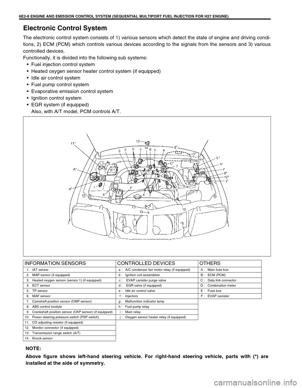
Electronic Control System
The electronic control system consists of 1) various sensors which detect the state of engine and driving condi-
tions, 2) ECM (PCM) which controls various devices according to the signals from the sensors and 3) various
controlled devices.
Functionally, it is divided into the following sub systems:
•Fuel injection control system
•Heated oxygen sensor heater control system (if equipped)
•Idle air control system
•Fuel pump control system
•Evaporative emission control system
•Ignition control system
•EGR system (if equipped)
Also, with A/T model, PCM controls A/T.
INFORMATION SENSORS CONTROLLED DEVICES OTHERS
1. IAT sensor a : A/C condenser fan motor relay (if equipped) A : Main fuse box
2. MAP sensor (if equipped) b : Ignition coil assemblies B : ECM (PCM)
3. Heated oxygen sensor (sensor 1) (if equipped) c : EVAP canister purge valve C : Data link connector
4. ECT sensor d : EGR valve (if equipped) D : Combination meter
5. TP sensor e : Idle air control valve E : Fuse box
6. MAF sensor f : Injectors F : EVAP canister
7. Camshaft position sensor (CMP sensor) g : Malfunction indicator lamp
8. ABS control module h : Fuel pump relay
9. Crankshaft position sensor (CKP sensor) (if equipped) i : Main relay
10. Power steering pressure switch (PSP switch) j : Oxygen sensor heater relay (if equipped)
11. CO adjusting resistor (if equipped)
12. Monitor connector (if equipped)
13. Transmission range switch (A/T)
14. Knock sensor
NOTE:
Above figure shows left-hand steering vehicle. For right-hand steering vehicle, parts with (*) are
installed at the side of symmetry.
Page 343 of 656
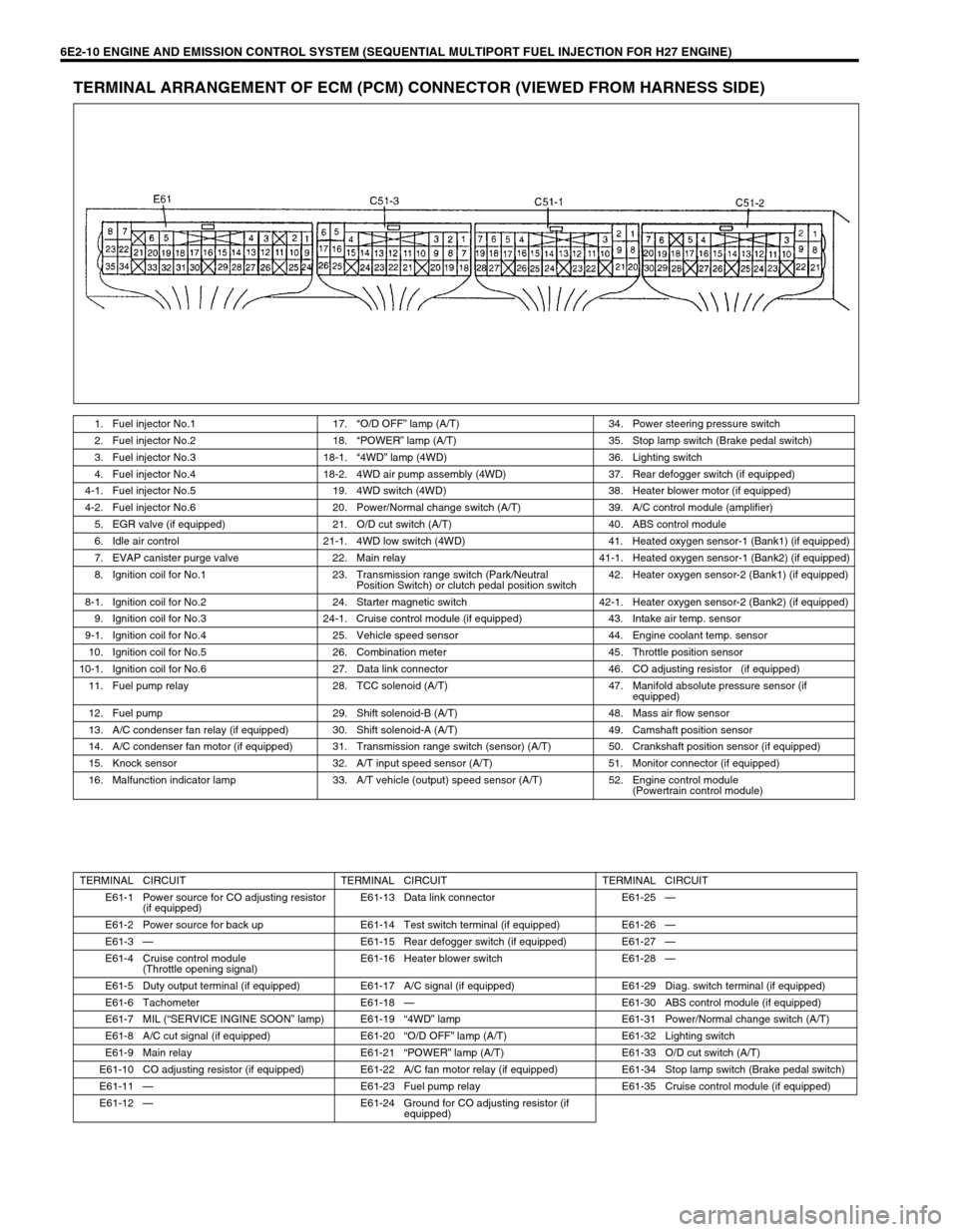
6E2-10 ENGINE AND EMISSION CONTROL SYSTEM (SEQUENTIAL MULTIPORT FUEL INJECTION FOR H27 ENGINE)
TERMINAL ARRANGEMENT OF ECM (PCM) CONNECTOR (VIEWED FROM HARNESS SIDE)
1. Fuel injector No.1 17.“O/D OFF” lamp (A/T) 34. Power steering pressure switch
2. Fuel injector No.2 18.“POWER” lamp (A/T) 35. Stop lamp switch (Brake pedal switch)
3. Fuel injector No.3 18-1.“4WD” lamp (4WD) 36. Lighting switch
4. Fuel injector No.4 18-2. 4WD air pump assembly (4WD) 37. Rear defogger switch (if equipped)
4-1. Fuel injector No.5 19. 4WD switch (4WD) 38. Heater blower motor (if equipped)
4-2. Fuel injector No.6 20. Power/Normal change switch (A/T) 39. A/C control module (amplifier)
5. EGR valve (if equipped) 21. O/D cut switch (A/T) 40. ABS control module
6. Idle air control 21-1. 4WD low switch (4WD) 41. Heated oxygen sensor-1 (Bank1) (if equipped)
7. EVAP canister purge valve 22. Main relay 41-1. Heated oxygen sensor-1 (Bank2) (if equipped)
8. Ignition coil for No.1 23. Transmission range switch (Park/Neutral
Position Switch) or clutch pedal position switch42. Heater oxygen sensor-2 (Bank1) (if equipped)
8-1. Ignition coil for No.2 24. Starter magnetic switch 42-1. Heater oxygen sensor-2 (Bank2) (if equipped)
9. Ignition coil for No.3 24-1. Cruise control module (if equipped) 43. Intake air temp. sensor
9-1. Ignition coil for No.4 25. Vehicle speed sensor 44. Engine coolant temp. sensor
10. Ignition coil for No.5 26. Combination meter 45. Throttle position sensor
10-1. Ignition coil for No.6 27. Data link connector 46. CO adjusting resistor (if equipped)
11. Fuel pump relay 28. TCC solenoid (A/T) 47. Manifold absolute pressure sensor (if
equipped)
12. Fuel pump 29. Shift solenoid-B (A/T) 48. Mass air flow sensor
13. A/C condenser fan relay (if equipped) 30. Shift solenoid-A (A/T) 49. Camshaft position sensor
14. A/C condenser fan motor (if equipped) 31. Transmission range switch (sensor) (A/T) 50. Crankshaft position sensor (if equipped)
15. Knock sensor 32. A/T input speed sensor (A/T) 51. Monitor connector (if equipped)
16. Malfunction indicator lamp 33. A/T vehicle (output) speed sensor (A/T) 52. Engine control module
(Powertrain control module)
TERMINAL CIRCUIT TERMINAL CIRCUIT TERMINAL CIRCUIT
E61-1 Power source for CO adjusting resistor
(if equipped)E61-13 Data link connector E61-25—
E61-2 Power source for back up E61-14 Test switch terminal (if equipped) E61-26—
E61-3—E61-15 Rear defogger switch (if equipped) E61-27—
E61-4 Cruise control module
(Throttle opening signal)E61-16 Heater blower switch E61-28—
E61-5 Duty output terminal (if equipped) E61-17 A/C signal (if equipped) E61-29 Diag. switch terminal (if equipped)
E61-6 Tachometer E61-18—E61-30 ABS control module (if equipped)
E61-7 MIL (“SERVICE INGINE SOON” lamp) E61-19“4WD” lamp E61-31 Power/Normal change switch (A/T)
E61-8 A/C cut signal (if equipped) E61-20“O/D OFF” lamp (A/T) E61-32 Lighting switch
E61-9 Main relay E61-21“POWER” lamp (A/T) E61-33 O/D cut switch (A/T)
E61-10 CO adjusting resistor (if equipped) E61-22 A/C fan motor relay (if equipped) E61-34 Stop lamp switch (Brake pedal switch)
E61-11—E61-23 Fuel pump relay E61-35 Cruise control module (if equipped)
E61-12—E61-24 Ground for CO adjusting resistor (if
equipped)
Page 344 of 656
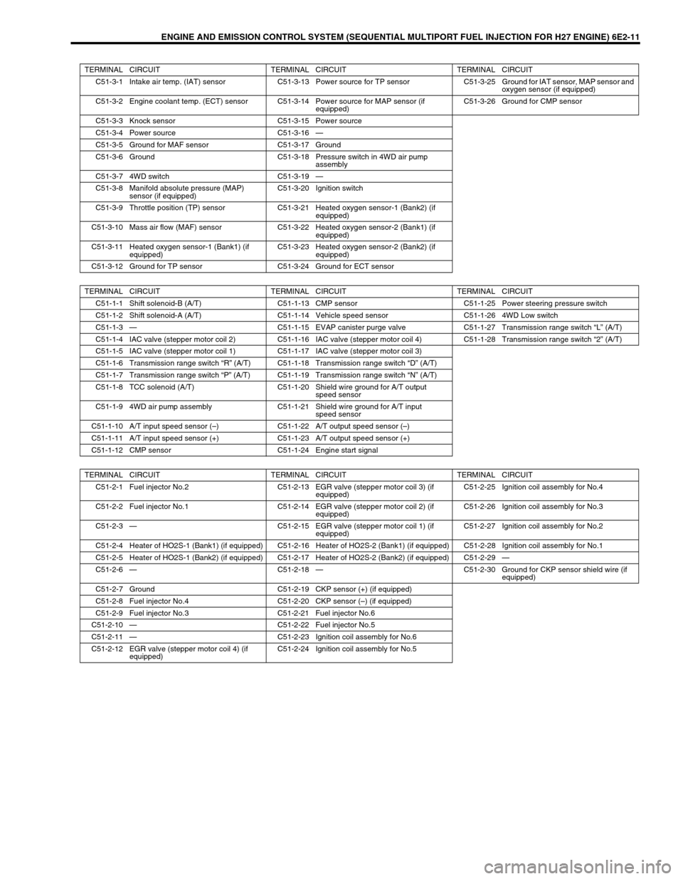
ENGINE AND EMISSION CONTROL SYSTEM (SEQUENTIAL MULTIPORT FUEL INJECTION FOR H27 ENGINE) 6E2-11
TERMINAL CIRCUIT TERMINAL CIRCUIT TERMINAL CIRCUIT
C51-3-1 Intake air temp. (IAT) sensor C51-3-13 Power source for TP sensor C51-3-25 Ground for IAT sensor, MAP sensor and
oxygen sensor (if equipped)
C51-3-2 Engine coolant temp. (ECT) sensor C51-3-14 Power source for MAP sensor (if
equipped)C51-3-26 Ground for CMP sensor
C51-3-3 Knock sensor C51-3-15 Power source
C51-3-4 Power source C51-3-16—
C51-3-5 Ground for MAF sensor C51-3-17 Ground
C51-3-6 Ground C51-3-18 Pressure switch in 4WD air pump
assembly
C51-3-7 4WD switch C51-3-19—
C51-3-8 Manifold absolute pressure (MAP)
sensor (if equipped)C51-3-20 Ignition switch
C51-3-9 Throttle position (TP) sensor C51-3-21 Heated oxygen sensor-1 (Bank2) (if
equipped)
C51-3-10 Mass air flow (MAF) sensor C51-3-22 Heated oxygen sensor-2 (Bank1) (if
equipped)
C51-3-11 Heated oxygen sensor-1 (Bank1) (if
equipped)C51-3-23 Heated oxygen sensor-2 (Bank2) (if
equipped)
C51-3-12 Ground for TP sensor C51-3-24 Ground for ECT sensor
TERMINAL CIRCUIT TERMINAL CIRCUIT TERMINAL CIRCUIT
C51-1-1 Shift solenoid-B (A/T) C51-1-13 CMP sensor C51-1-25 Power steering pressure switch
C51-1-2 Shift solenoid-A (A/T) C51-1-14 Vehicle speed sensor C51-1-26 4WD Low switch
C51-1-3—C51-1-15 EVAP canister purge valve C51-1-27 Transmission range switch “L” (A/T)
C51-1-4 IAC valve (stepper motor coil 2) C51-1-16 IAC valve (stepper motor coil 4) C51-1-28 Transmission range switch “2” (A/T)
C51-1-5 IAC valve (stepper motor coil 1) C51-1-17 IAC valve (stepper motor coil 3)
C51-1-6 Transmission range switch “R” (A/T) C51-1-18 Transmission range switch “D” (A/T)
C51-1-7 Transmission range switch “P” (A/T) C51-1-19 Transmission range switch “N” (A/T)
C51-1-8 TCC solenoid (A/T) C51-1-20 Shield wire ground for A/T output
speed sensor
C51-1-9 4WD air pump assembly C51-1-21 Shield wire ground for A/T input
speed sensor
C51-1-10 A/T input speed sensor (–) C51-1-22 A/T output speed sensor (–)
C51-1-11 A/T input speed sensor (+) C51-1-23 A/T output speed sensor (+)
C51-1-12 CMP sensor C51-1-24 Engine start signal
TERMINAL CIRCUIT TERMINAL CIRCUIT TERMINAL CIRCUIT
C51-2-1 Fuel injector No.2 C51-2-13 EGR valve (stepper motor coil 3) (if
equipped)C51-2-25 Ignition coil assembly for No.4
C51-2-2 Fuel injector No.1 C51-2-14 EGR valve (stepper motor coil 2) (if
equipped)C51-2-26 Ignition coil assembly for No.3
C51-2-3—C51-2-15 EGR valve (stepper motor coil 1) (if
equipped)C51-2-27 Ignition coil assembly for No.2
C51-2-4 Heater of HO2S-1 (Bank1) (if equipped) C51-2-16 Heater of HO2S-2 (Bank1) (if equipped) C51-2-28 Ignition coil assembly for No.1
C51-2-5 Heater of HO2S-1 (Bank2) (if equipped) C51-2-17 Heater of HO2S-2 (Bank2) (if equipped) C51-2-29—
C51-2-6—C51-2-18—C51-2-30 Ground for CKP sensor shield wire (if
equipped)
C51-2-7 Ground C51-2-19 CKP sensor (+) (if equipped)
C51-2-8 Fuel injector No.4 C51-2-20 CKP sensor (–) (if equipped)
C51-2-9 Fuel injector No.3 C51-2-21 Fuel injector No.6
C51-2-10—C51-2-22 Fuel injector No.5
C51-2-11—C51-2-23 Ignition coil assembly for No.6
C51-2-12 EGR valve (stepper motor coil 4) (if
equipped)C51-2-24 Ignition coil assembly for No.5