change wheel SUZUKI GRAND VITARA 2008 3.G User Guide
[x] Cancel search | Manufacturer: SUZUKI, Model Year: 2008, Model line: GRAND VITARA, Model: SUZUKI GRAND VITARA 2008 3.GPages: 290, PDF Size: 4.99 MB
Page 212 of 290
9-5INSPECTION AND MAINTENANCE
66J22-03E
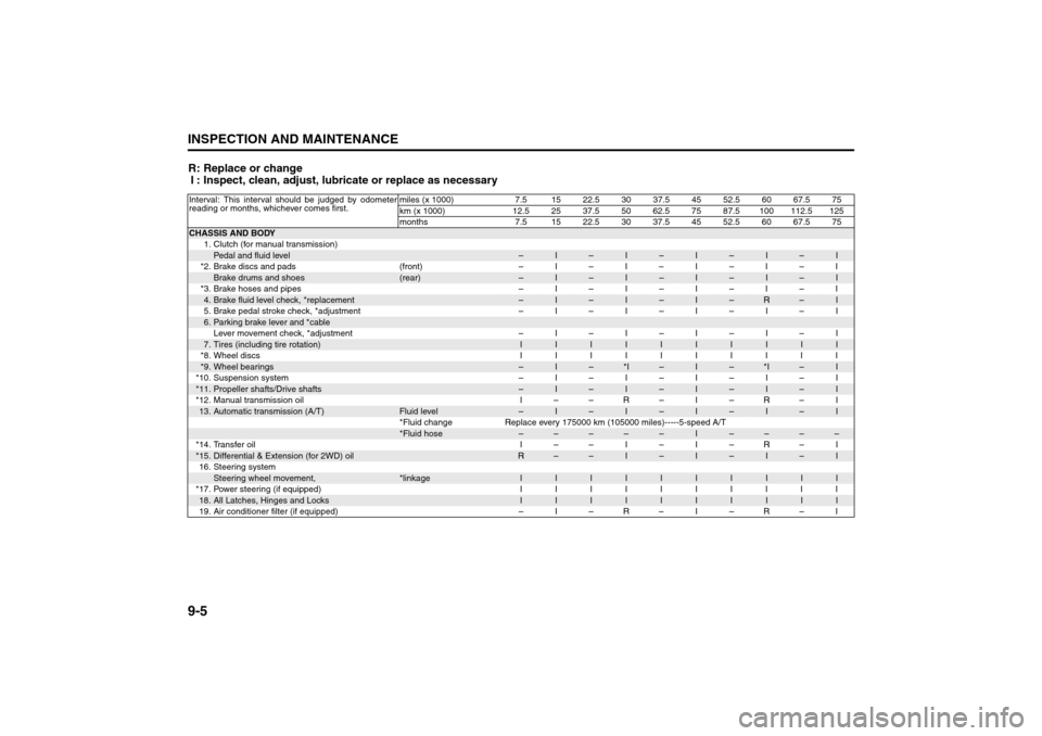
R: Replace or change
I : Inspect, clean, adjust, lubricate or replace as necessaryInterval: This interval should be judged by odometer
reading or months, whichever comes first.miles (x 1000) 7.5 15 22.5 30 37.5 45 52.5 60 67.5 75
km (x 1000) 12.5 25 37.5 50 62.5 75 87.5 100 112.5 125
months 7.5 15 22.5 30 37.5 45 52.5 60 67.5 75CHASSIS AND BODY
1. Clutch (for manual transmission)
Pedal and fluid level
–
I
–
I
–
I
–
I
–
I
*2. Brake discs and pads (front) – I – I – I – I – I
Brake drums and shoes
(rear)
–
I
–
I
–
I
–
I
–
I
*3. Brake hoses and pipes – I – I – I – I – I
4.Brake fluid level check, *replacement
–
I
–
I
–
I
–
R
–
I
5. Brake pedal stroke check, *adjustment – I – I – I – I – I
6.Parking brake lever and *cableLever movement check, *adjustment – I – I – I – I – I7.Tires (including tire rotation)
I
I
I
I
I
I
I
I
I
I
*8. Wheel discs I I I I I I I I I I
*9.
Wheel bearings
–
I
–
*I
–
I
–
*I
–
I
*10. Suspension system – I – I – I – I – I
*11.
Propeller shafts/Drive shafts
–
I
–
I
–
I
–
I
–
I
*12. Manual transmission oil I – – R – I – R – I
13.
Automatic transmission (A/T)
Fluid level
–
I
–
I
–
I
–
I
–
I
*Fluid change Replace every 175000 km (105000 miles)-----5-speed A/T
*Fluid hose
–
–
–
–
–
I
–
–
–
–
*14. Transfer oil I – – I – I – R – I
*15.
Differential & Extension (for 2WD) oil
R
–
–
I
–
I
–
I
–
I
16. Steering system
Steering wheel movement,
*linkage
I
I
I
I
I
I
I
I
I
I
*17. Power steering (if equipped) I I I I I I I I I I
18.
All Latches, Hinges and Locks
I
I
I
I
I
I
I
I
I
I
19. Air conditioner filter (if equipped) – I – R – I – R – I
Periodic Maintenance Schedule: 1, 2, 3, 4, 5, 6, 9, 10
Page 213 of 290
9-6
INSPECTION AND MAINTENANCE
66J22-03E
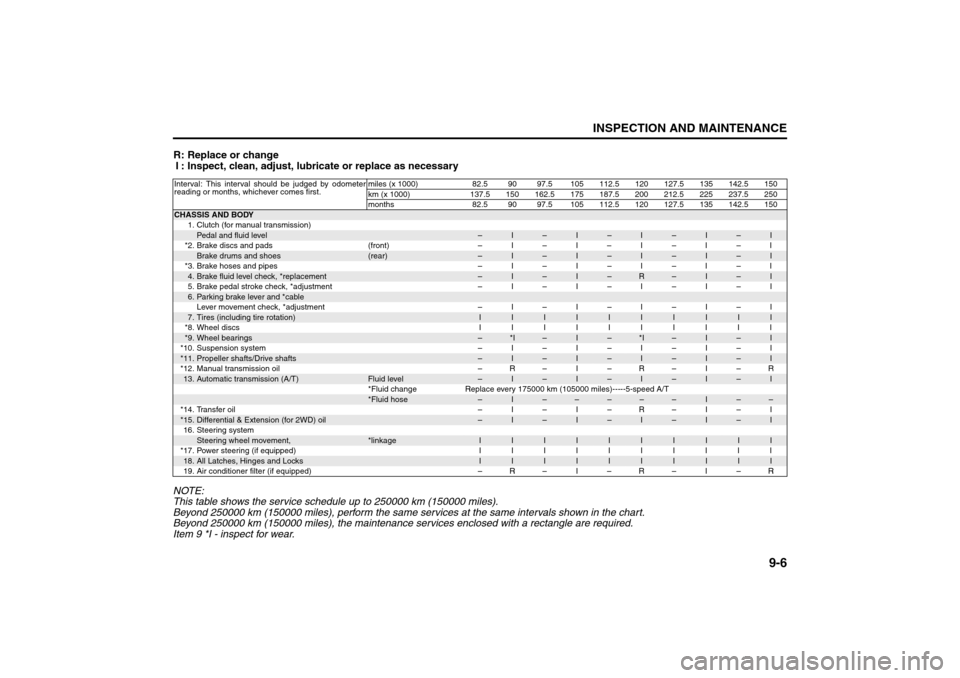
R: Replace or change
I : Inspect, clean, adjust, lubricate or replace as necessary
NOTE:
This table shows the service schedule up to 250000 km (150000 miles).
Beyond 250000 km (150000 miles), perform the same services at the same intervals shown in the chart.
Beyond 250000 km (150000 miles), the maintenance services enclosed with a rectangle are required.
Item 9 *I - inspect for wear.Interval: This interval should be judged by odometer
reading or months, whichever comes first.miles (x 1000) 82.5 90 97.5 105 112.5 120 127.5 135 142.5 150
km (x 1000) 137.5 150 162.5 175 187.5 200 212.5 225 237.5 250
months 82.5 90 97.5 105 112.5 120 127.5 135 142.5 150CHASSIS AND BODY
1. Clutch (for manual transmission)
Pedal and fluid level
–
I
–
I
–
I
–
I
–
I
*2. Brake discs and pads (front) – I – I – I – I – I
Brake drums and shoes
(rear)
–
I
–
I
–
I
–
I
–
I
*3. Brake hoses and pipes – I – I – I – I – I
4.Brake fluid level check, *replacement
–
I
–
I
–
R
–
I
–
I
5. Brake pedal stroke check, *adjustment – I – I – I – I – I
6.Parking brake lever and *cableLever movement check, *adjustment – I – I – I – I – I7.Tires (including tire rotation)
I
I
I
I
I
I
I
I
I
I
*8. Wheel discs I I I I I I I I I I
*9.
Wheel bearings
–
*I
–
I
–
*I
–
I
–
I
*10. Suspension system – I – I – I – I – I
*11.
Propeller shafts/Drive shafts
–
I
–
I
–
I
–
I
–
I
*12. Manual transmission oil – R – I – R – I – R
13.
Automatic transmission (A/T)
Fluid level
–
I
–
I
–
I
–
I
–
I
*Fluid change Replace every 175000 km (105000 miles)-----5-speed A/T
*Fluid hose
–
I
–
–
–
–
–
I
–
–
*14. Transfer oil – I – I – R – I – I
*15.
Differential & Extension (for 2WD) oil
–
I
–
I
–
I
–
I
–
I
16. Steering system
Steering wheel movement,
*linkage
I
I
I
I
I
I
I
I
I
I
*17. Power steering (if equipped) I I I I I I I I I I
18.
All Latches, Hinges and Locks
I
I
I
I
I
I
I
I
I
I
19. Air conditioner filter (if equipped) – R – I – R – I – R
Periodic Maintenance Schedule: 1, 2, 3, 4, 5, 6, 9, 10
Page 233 of 290
9-26
INSPECTION AND MAINTENANCE
66J22-03E
D. Construction Code
This letter code is used to indicate the
type of ply construction in the tire. The
letter “R” means radial ply tire con-
struction, the letter “D” means diago-
nal or bias ply construction, and the
letter “B” means belted-bias ply con-
struction.
E. Rim Diameter
This two-digit number is the wheel or
rim diameter in inches.
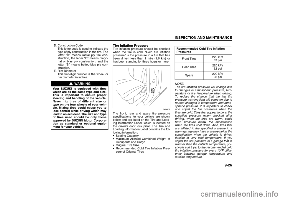
Tire Inflation PressureTire inflation pressure should be checked
when the tire is cold. “Cold tire inflation
pressure” is the pressure in a tire that has
been driven less than 1 mile (1.6 km) or
has been standing for three hours or more.
54G307
The front, rear and spare tire pressure
specifications for your vehicle are shown
below and are listed on the Tire and Load-
ing Information Label, which is located on
the driver’s door lock pillar. The Tire and
Loading Information Label contains the fol-
lowing information:
Seating Capacity
Maximum Allowed Combined Weight of
Occupants and Cargo
Original Tire Size
Recommended Cold Tire Inflation Pres-
sure of Original TiresNOTE:
The tire inflation pressure will change due
to changes in atmospheric pressure, tem-
perature or tire temperature when driving.
To reduce the chance that the low tire
pressure warning light will come on due to
normal changes in temperature and atmo-
spheric pressure, it is important to check
and adjust the tire pressures when the
tires are cold. Tires that appear to be at the
specified pressure when checked after
driving, when the tires are warm, could
have pressure below the specification
when the tires cool down. Also, tires that
are inflated to the specified pressure in a
warm garage may have pressure below the
specification when the vehicle is driven
outside in very cold temperature. If you
adjust the tire pressure in a garage that is
warmer than the outside temperature, you
should add 1 psi to the recommended cold
tire inflation pressure for every 10°F differ-
ence between garage temperature and
outside temperature.
WARNING
Your SUZUKI is equipped with tires
which are all the same type and size.
This is important to ensure proper
steering and handling of the vehicle.
Never mix tires of different size or
type on the four wheels of your vehi-
cle. Mixing tires could cause you to
lose control while driving which may
lead to an accident. The size and type
of tires used should be only those
approved by SUZUKI Motor Corpora-
tion as standard or optional equip-
ment for your vehicle.
Recommended Cold Tire Inflation
Pressures
Front Tires220 kPa
32 psi
Rear Tires220 kPa
32 psi
Spare220 kPa
32 psi
Tires: 6
Page 235 of 290
9-28
INSPECTION AND MAINTENANCE
66J22-03E
damage should be replaced. If any tires
show abnormal wear, have them
inspected by your SUZUKI dealer.
4) Check for loose wheel nuts.
5) Check that there are no nails, stones or
other objects sticking into the tires.
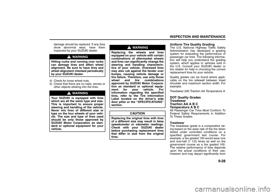
Uniform Tire Quality GradingThe U.S. National Highway Traffic Safety
Administration has developed a grading
system for evaluating the performance of
passenger car tires. The following informa-
tion will help you understand the grading
system, which applies to vehicles sold in
the U.S. Consult your SUZUKI dealer or
tire retailer for help in choosing the correct
replacement tires for your vehicle.
Quality grades can be found where appli-
cable on the tire sidewall between tread
shoulder and maximum section width. For
example:
Treadwear 200 Traction AA Temperature ADOT Quality Grades
Treadwear
Traction AA A B C
Temperature A B CAll Passenger Car Tires Must Conform To
Federal Safety Requirements in Addition
To These Grades
Treadwear
The treadwear grade is a comparative rat-
ing based on the wear rate of the tire when
tested under controlled conditions on a
specified government test course. For
example, a tire graded 150 would wear one
and one-half (1 1/2) times as well on the
government course as a tire graded 100.
The relative performance of tires depends
upon the actual conditions of their use,
however and may depart significantly from
WARNING
Hitting curbs and running over rocks
can damage tires and affect wheel
alignment. Be sure to have tires and
wheel alignment checked periodically
by your SUZUKI dealer.
WARNING
Your SUZUKI is equipped with tires
which are all the same type and size.
This is important to ensure proper
steering and handling of the vehicle.
Never mix tires of different size or
type on the four wheels of your vehi-
cle. The size and type of tires used
should be only those approved by
SUZUKI Motor Corporation as stan-
dard or optional equipment for your
vehicle.
WARNING
Replacing the wheels and tires
equipped on your vehicle with certain
combinations of aftermarket wheels
and tires can significantly change the
steering and handling characteris-
tics of your vehicle. Oversized tires
may also rub against the fender over
bumps, causing vehicle damage or
tire failure. Therefore, use only those
wheel and tire combinations
approved by SUZUKI Motor Corpora-
tion as standard or optional equip-
ment for your vehicle. For
information regarding the specified
tires, refer to the Tire Information
Label located on the driver’s side
door pillar or the “SPECIFICATIONS”
section.
CAUTION
Replacing the original tires with tires
of a different size may result in false
speedometer or odometer readings.
Check with your SUZUKI dealer
before purchasing replacement tires
that differ in size from the original
tires.
Tires: 6
Page 236 of 290
9-29INSPECTION AND MAINTENANCE
66J22-03E
the norm due to variations in driving habits,
service practices and differences in road
characteristics and climate.
Traction – AA, A, B, C
The traction grades, from highest to low-
est, are AA, A, B and C. Those grades rep-
resent the tire’s ability to stop on wet
pavement as measured under controlled
conditions on specified government test
surfaces of asphalt and concrete. A tire
marked C may have poor traction perfor-
mance.
Temperature – A, B, C
The temperature grades are A (the high-
est), B and C, representing the tire’s resis-
tance to the generation of heat and its
ability to dissipate heat when tested under
controlled conditions on a specified indoor
laboratory test wheel. Sustained high tem-
perature can cause the material of the tire
to degenerate and reduce tire life, and
excessive temperature can lead to sudden
tire failure. The grade C corresponds to a
level of performance which all passenger
car tires must meet under the FederalMotor Vehicle Safety Standard No. 109.
Grades B and A represent higher levels of
performance on the laboratory test wheel
than the minimum required by law.
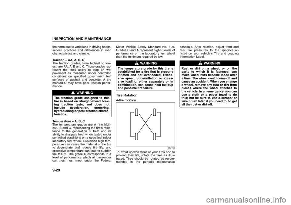
Tire Rotation4-tire rotation
65D459
To avoid uneven wear of your tires and to
prolong their life, rotate the tires as illus-
trated. Tires should be rotated as recom-
mended in the periodic maintenanceschedule. After rotation, adjust front and
rear tire pressures to the specification
listed on your vehicle’s Tire and Loading
Information Label.
WARNING
The traction grade assigned to this
tire is based on straight-ahead brak-
ing traction tests, and does not
include acceleration, cornering,
hydroplaning or peak traction charac-
teristics.
WARNING
The temperature grade for this tire is
established for a tire that is properly
inflated and not overloaded. Exces-
sive speed, underinflation or exces-
sive loading, either separately or in
combination, can cause heat buildup
and possible tire failure.
WARNING
Rust or dirt on a wheel, or on the
parts to which it is fastened, can
make wheel nuts become loose after
a time. The wheel could come off and
cause an accident. When you change
a wheel, remove any rust or dirt from
places where the wheel attaches to
the vehicle. In an emergency, you can
use a cloth or a paper towel to do
this; but be sure to use a scraper or
wire brush later, if you need to, to get
all the rust or dirt off.
Tires: 6
Page 237 of 290
9-30
INSPECTION AND MAINTENANCE
66J22-03E
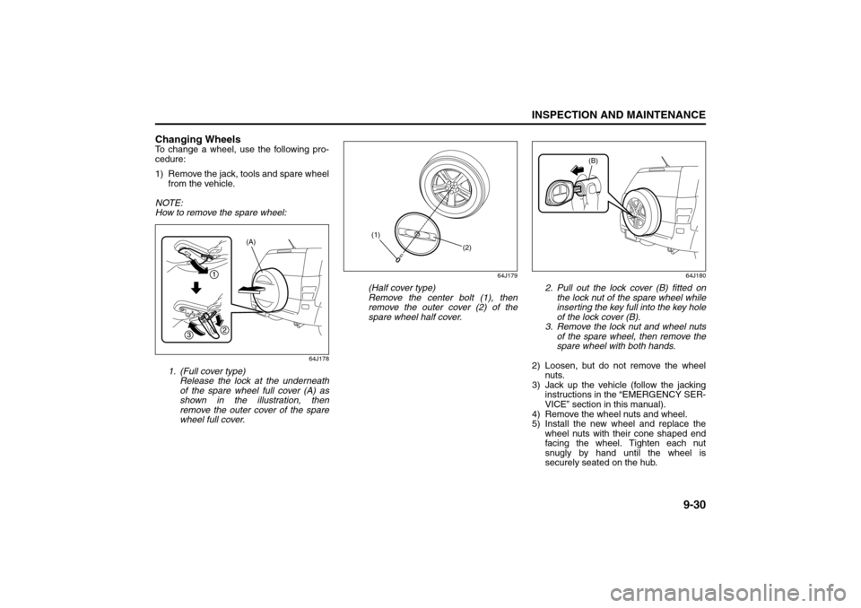
Changing WheelsTo change a wheel, use the following pro-
cedure:
1) Remove the jack, tools and spare wheel
from the vehicle.
NOTE:
How to remove the spare wheel:
64J178
1. (Full cover type)
Release the lock at the underneath
of the spare wheel full cover (A) as
shown in the illustration, then
remove the outer cover of the spare
wheel full cover.
64J179
(Half cover type)
Remove the center bolt (1), then
remove the outer cover (2) of the
spare wheel half cover.
64J180
2. Pull out the lock cover (B) fitted on
the lock nut of the spare wheel while
inserting the key full into the key hole
of the lock cover (B).
3. Remove the lock nut and wheel nuts
of the spare wheel, then remove the
spare wheel with both hands.
2) Loosen, but do not remove the wheel
nuts.
3) Jack up the vehicle (follow the jacking
instructions in the “EMERGENCY SER-
VICE” section in this manual).
4) Remove the wheel nuts and wheel.
5) Install the new wheel and replace the
wheel nuts with their cone shaped end
facing the wheel. Tighten each nut
snugly by hand until the wheel is
securely seated on the hub.
(A)
(2) (1)
(B)
Tires: 6
Page 257 of 290
10-2
EMERGENCY SERVICE
66J22-03E
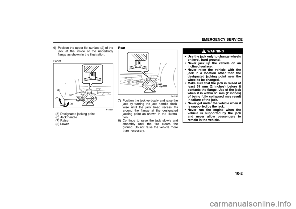
6) Position the upper flat surface (2) of the
jack at the inside of the underbody
flange as shown in the illustration.
Front
64J251
(5) Designated jacking point
(6) Jack handle
(7) Raise
(8) LowerRear
64J252
7) Position the jack vertically and raise the
jack by turning the jack handle clock-
wise until the jack head recess fits
around the flange at the designated
jacking point as shown in the illustra-
tion.
8) Continue to raise the jack slowly and
smoothly until the tire clears the
ground. Do not raise the vehicle more
than necessary.
(5)
(8) (7)(6)
WARNING
Use the jack only to change wheels
on level, hard ground.
Never jack up the vehicle on an
inclined surface.
Never raise the vehicle with the
jack in a location other than the
designated jacking point near the
wheel to be changed.
Make sure that the jack is raised at
least 51 mm (2 inches) before it
contacts the flange. Use of the jack
when it is within 51 mm (2 inches)
of being fully collapsed may result
in failure of the jack.
Never get under the vehicle when it
is supported by the jack.
Never run the engine when the
vehicle is supported by the jack
and never allow passengers to
remain in the vehicle.
Jacking Instructions: 5
Page 279 of 290

14-1
SPECIFICATIONS
66J22-03E
14
SPECIFICATIONSNOTE:
Specifications are subject to change with-
out notice.4WD: 4-wheel drive
2WD: 2-wheel driveM/T: Manual transmission
A/T: Automatic transmission
ITEM: Dimensions UNIT: mm (in.)
Overall length 4470 (176.0)
Overall width 1810 (71.3)
Overall height 4WD 1695 (66.7)
2WD 1683 (66.3)
Wheelbase 2640 (103.9)
Tread front 1540 (60.6)
rear 1560 (61.4)
Minimum running ground clearance 4WD 200 (7.9)
2WD 188 (7.4)
ITEM: Weight
Gross axle weight rating
See the safety certification label and the tire information label which
are located on the driver’s door lock pillar. Gross vehicle weight rating
Vehicle capacity weight
ITEM: Engine
Type H27A (24V DOHC)
Number of cylinders 6
Bore 88.0 mm (3.46 in.)
Stroke 75.0 mm (2.95 in.)
Piston displacement 2736 cm
3 (167.1 cu.in, 2736 cc)
Compression ratio 9.5 : 1
Specifications: 1, 2, 5, 6, 7, 10, 11