SUZUKI GRAND VITARA 2008 3.G Repair Manual
Manufacturer: SUZUKI, Model Year: 2008, Model line: GRAND VITARA, Model: SUZUKI GRAND VITARA 2008 3.GPages: 290, PDF Size: 4.99 MB
Page 61 of 290
STEERING COLUMN CONTROLS
3
66J22-03E
60G405
STEERING COLUMN CONTROLSIgnition Switch ..................................................................... 3-1
Lighting/Turn Signal Control Lever ................................... 3-5
Windshield Wiper and Washer Lever ................................ 3-8
Rear Window Wiper/Washer Switch .................................. 3-9
Tilt Steering Lock Lever ..................................................... 3-10
Cruise Control (if equipped) ............................................... 3-10
Remote Audio Controls (if equipped) ............................... 3-12
Horn ...................................................................................... 3-12
Page 62 of 290
3-1STEERING COLUMN CONTROLS
66J22-03E
65D611
Ignition SwitchVehicle Without Keyless Start Sys-
tem
60B041
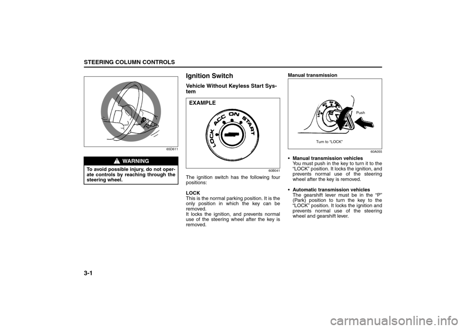
The ignition switch has the following four
positions:
LOCK
This is the normal parking position. It is the
only position in which the key can be
removed.
It locks the ignition, and prevents normal
use of the steering wheel after the key is
removed.Manual transmission
60A055
Manual transmission vehicles
You must push in the key to turn it to the
“LOCK” position. It locks the ignition, and
prevents normal use of the steering
wheel after the key is removed.
Automatic transmission vehicles
The gearshift lever must be in the “P”
(Park) position to turn the key to the
“LOCK” position. It locks the ignition and
prevents normal use of the steering
wheel and gearshift lever.
WARNING
To avoid possible injury, do not oper-
ate controls by reaching through the
steering wheel.
EXAMPLE
Push
Turn to “LOCK”
Ignition Switch: 8, 10
Page 63 of 290
3-2
STEERING COLUMN CONTROLS
66J22-03E
ACC
Accessories such as the radio can oper-
ate, but the engine is off.
ON
This is the normal operating position. All
electrical systems are on.
START
This is the position for starting the engine
using the starter motor. The key should be
released from this position as soon as the
engine starts.
Ignition key reminder (if equipped)
A buzzer sounds intermittently to remind
you to remove the ignition key if it is in the
ignition switch when the driver’s door is
opened.
Vehicle With Keyless Start System
63J270
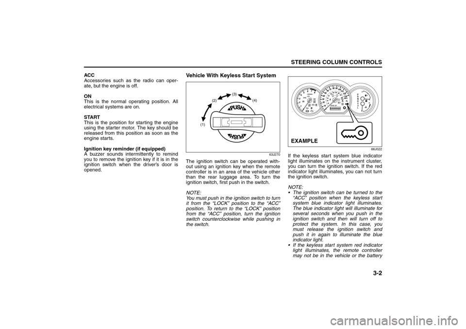
The ignition switch can be operated with-
out using an ignition key when the remote
controller is in an area of the vehicle other
than the rear luggage area. To turn the
ignition switch, first push in the switch.
NOTE:
You must push in the ignition switch to turn
it from the “LOCK” position to the “ACC”
position. To return to the “LOCK” position
from the “ACC” position, turn the ignition
switch counterclockwise while pushing in
the switch.
66J022
If the keyless start system blue indicator
light illuminates on the instrument cluster,
you can turn the ignition switch. If the red
indicator light illuminates, you can not turn
the ignition switch.
NOTE:
The ignition switch can be turned to the
“ACC” position when the keyless start
system blue indicator light illuminates.
The blue indicator light will illuminate for
several seconds when you push in the
ignition switch and then will turn off to
protect the system. In this case, you
must release the ignition switch and
push it in again to illuminate the blue
indicator light.
If the keyless start system red indicator
light illuminates, the remote controller
may not be in the vehicle or the battery
(1)(2)(3)
(4)
EXAMPLE
Ignition Switch: 8, 10
Page 64 of 290

3-3STEERING COLUMN CONTROLS
66J22-03E
of the remote controller may be unreli-
able.
NOTE:
If the battery of the remote controller
runs down or there are strong radio
waves or noise, the operating range may
be narrower or the remote controller may
be inoperative.
If the remote controller is too close to the
door glass, it may not operate.
The ignition switch may not turn when
the remote controller is on the instru-
ment panel, in the glove box, in the door
pocket, in the sun visor or on the floor.
You can also turn the ignition switch by
inserting the ignition key into the slot.The ignition switch has the following four
positions:
LOCK (1)
This is the normal parking position. It is the
only position in which the key can be
removed. It locks the ignition, and prevents
normal use of the steering wheel.
For vehicles with an automatic transmis-
sion, the gearshift lever must be in the “P”
(Park) position to turn the key to the
“LOCK” position.
To release the steering lock, turn the igni-
tion switch clockwise to one of the other
positions. If you have trouble turning the
ignition switch to unlock the steering, try
turning the steering wheel slightly to the
right or left while turning the switch.
NOTE:
You must push the ignition switch in to turn
it to the “ACC” position. Also you must
push the ignition switch in to return it to the
“LOCK” position.
ACC (2)
Accessories such as the radio can oper-
ate, but the engine is off.
ON (3)
This is the normal operating position. All
electrical systems are on.START (4)
This is the position for starting the engine
using the starter motor. The switch should
be released from this position as soon as
the engine starts.
Ignition switch reminder
(When using the keyless start system)
A buzzer sounds intermittently to remind
you to return the ignition switch to the
“LOCK” position if it is in the “ACC” position
when the driver’s door is opened.
Ignition key reminder
(When using the ignition key)
A buzzer sounds intermittently to remind
you to remove the ignition key if it is in the
ignition switch when the driver’s door is
opened.
CAUTION
The remote controller is a sensitive
electronic instrument. To avoid dam-
aging the remote controller:
Do not expose it to impacts, mois-
ture or high temperature such as by
leaving it on the dashboard under
direct sunlight.
Keep the remote controller away
from magnetic objects such as a
television.
Ignition Switch: 8, 10
Page 65 of 290
3-4
STEERING COLUMN CONTROLS
66J22-03E
64J216
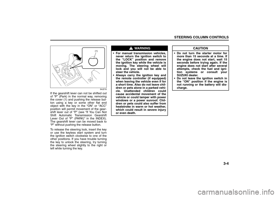
If the gearshift lever can not be shifted out
of “P” (Park) in the normal way, removing
the cover (1) and pushing the release but-
ton using a key or some other flat end
object with the key in the “ON” or “ACC”
position will permit movement of the gear-
shift lever out of “P” (see “If You Can Not
Shift Automatic Transmission Gearshift
Lever Out of “P” (PARK)” in the INDEX).
The gearshift lever can be moved back to
“P” without pushing the release button.
To release the steering lock, insert the key
or use the keyless start system and turn
the ignition switch clockwise to one of the
other positions. If you have trouble turning
the key to unlock the steering, try turning
the steering wheel slightly to the right or
left while turning the key.
(1)
WARNING
For manual transmission vehicles,
never return the ignition switch to
the “LOCK” position and remove
the ignition key while the vehicle is
moving. The steering wheel will
lock and you will not be able to
steer the vehicle.
Always carry the ignition key and
the remote controller (if equipped)
when leaving the vehicle even if for
a short time. Also do not leave chil-
dren or pets alone in a parked vehi-
cle. Unattended children could
cause accidental movement of the
vehicle or could tamper with power
windows or a power sunroof. Chil-
dren or pets could also suffer from
heatstroke in warm or hot weather,
which could result in severe injury
or even death.
CAUTION
Do not turn the starter motor for
more than 15 seconds at a time. If
the engine does not start, wait 15
seconds before trying again. If the
engine does not start after several
attempts, check the fuel and igni-
tion systems or consult your
SUZUKI dealer.
Do not leave the ignition switch in
the “ON” position if the engine is
not running or the battery will dis-
charge.
Ignition Switch: 8, 10
Page 66 of 290
3-5STEERING COLUMN CONTROLS
66J22-03E
Lighting/Turn Signal Control
Lever
66J023
52D166
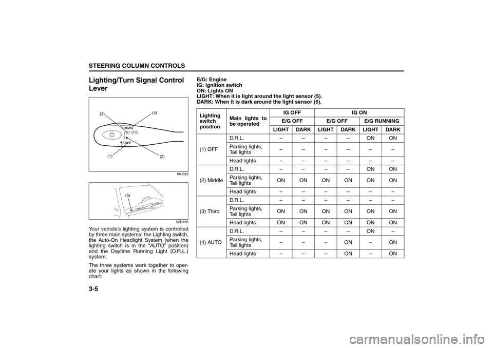
Your vehicle’s lighting system is controlled
by three main systems: the Lighting switch,
the Auto-On Headlight System (when the
lighting switch is in the “AUTO” position)
and the Daytime Running Light (D.R.L.)
system.
The three systems work together to oper-
ate your lights as shown in the following
chart:
(1)
(2) (3)(4)
E/G: Engine
IG: Ignition switch
ON: Lights ON
LIGHT: When it is light around the light sensor (5).
DARK: When it is dark around the light sensor (5).
Lighting
switch
positionMain lights to
be operatedIG OFF IG ON
E/G OFF E/G OFF E/G RUNNING
LIGHT DARK LIGHT DARK LIGHT DARK
(1) OFFD.R.L. ––––ONON
Parking lights,
Tail lights––––––
Head lights ––––––
(2) MiddleD.R.L. ––––ONON
Parking lights,
Tail lightsON ON ON ON ON ON
Head lights ––––––
(3) ThirdD.R.L. ––––––
Parking lights,
Tail lightsON ON ON ON ON ON
Head lights ONONONONONON
(4) AUTOD.R.L. ––––ON–
Parking lights,
Tail lights–––ON–ON
Head lights – – – ON – ON
Lighting/Turn Signal Control Lever: 7, 8
Page 67 of 290
3-6
STEERING COLUMN CONTROLS
66J22-03E
Lighting Operation
66J024
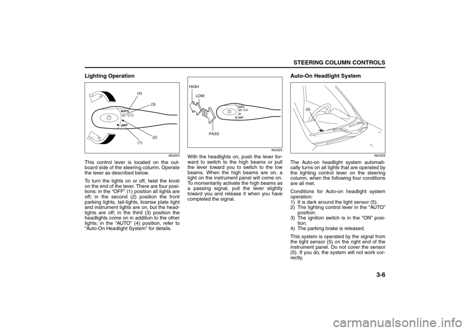
This control lever is located on the out-
board side of the steering column. Operate
the lever as described below.
To turn the lights on or off, twist the knob
on the end of the lever. There are four posi-
tions: in the “OFF” (1) position all lights are
off; in the second (2) position the front
parking lights, tail-lights, license plate light
and instrument lights are on, but the head-
lights are off; in the third (3) position the
headlights come on in addition to the other
lights; in the “AUTO” (4) position, refer to
“Auto-On Headlight System” for details.
66J025
With the headlights on, push the lever for-
ward to switch to the high beams or pull
the lever toward you to switch to the low
beams. When the high beams are on, a
light on the instrument panel will come on.
To momentarily activate the high beams as
a passing signal, pull the lever slightly
toward you and release it when you have
completed the signal.
Auto-On Headlight System
66J026
The Auto-on headlight system automati-
cally turns on all lights that are operated by
the lighting control lever on the steering
column, when the following four conditions
are all met.
Conditions for Auto-on headlight system
operation:
1) It is dark around the light sensor (5).
2) The lighting control lever in the “AUTO”
position.
3) The ignition switch is in the “ON” posi-
tion.
4) The parking brake is released.
This system is operated by the signal from
the light sensor (5) on the right end of the
instrument panel. Do not cover the sensor
(5). If you do, the system will not work cor-
rectly.
(1)(2) (3) (4)
HIGH
LOW
PASS
(5)
Lighting/Turn Signal Control Lever: 7, 8
Page 68 of 290
3-7STEERING COLUMN CONTROLS
66J22-03E
NOTE:
This system does not react to all types of
ambient light. As the sensor is infrared
type, it will not work correctly with ambient
lights that do not contain infrared rays.
Daytime Running Light (D.R.L.)
SystemThe headlights light, but are dimmer than
the low beam, when the following three
conditions are all met. Also, the D.R.L. indi-
cator light on the instrument panel comes
on.
Conditions for D.R.L. system operation:
1) The engine is running.
2) The parking brake is released.
3) The lighting switch is in either the “OFF”
or the “Second” position: or The lighting
switch is in the “AUTO” position and it is
light around the light sensor.
NOTE:
Be sure to turn the lighting switch to the
third position at night or at any time of the
day when driving or weather conditions
require the headlights to operate at full
brightness and the taillights to be on.
Lights “On” reminder
A buzzer sounds to remind you to turn off
the lights if they are left on when the igni-
tion key is removed and the driver’s door is
opened.
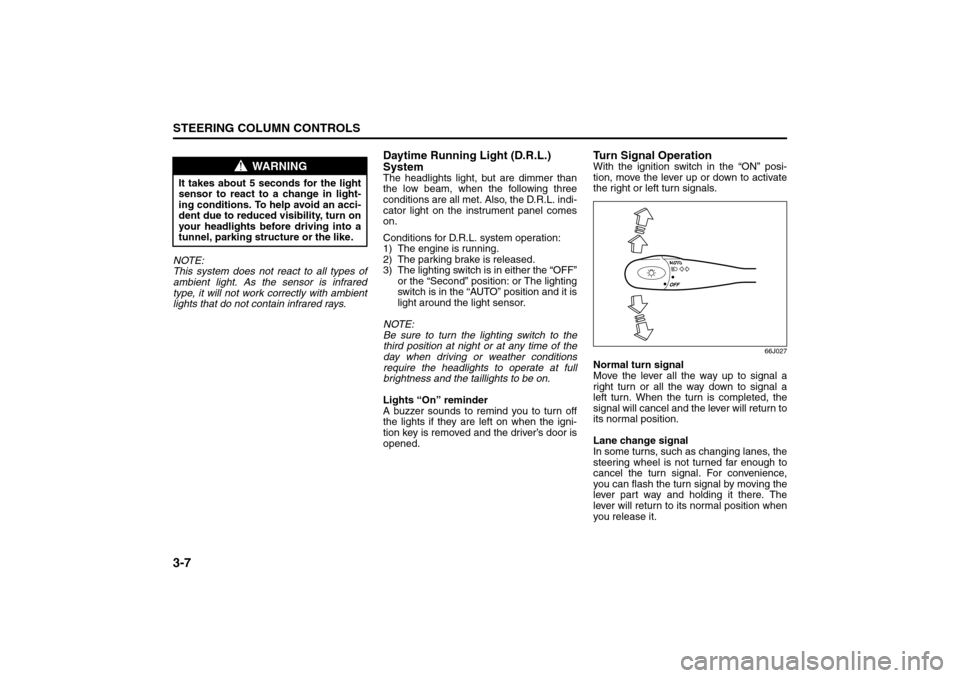
Turn Signal OperationWith the ignition switch in the “ON” posi-
tion, move the lever up or down to activate
the right or left turn signals.
66J027
Normal turn signal
Move the lever all the way up to signal a
right turn or all the way down to signal a
left turn. When the turn is completed, the
signal will cancel and the lever will return to
its normal position.
Lane change signal
In some turns, such as changing lanes, the
steering wheel is not turned far enough to
cancel the turn signal. For convenience,
you can flash the turn signal by moving the
lever part way and holding it there. The
lever will return to its normal position when
you release it.
WARNING
It takes about 5 seconds for the light
sensor to react to a change in light-
ing conditions. To help avoid an acci-
dent due to reduced visibility, turn on
your headlights before driving into a
tunnel, parking structure or the like.
Lighting/Turn Signal Control Lever: 7, 8
Page 69 of 290
3-8
STEERING COLUMN CONTROLS
66J22-03E
Windshield Wiper and Washer
LeverWindshield Wipers
63J283
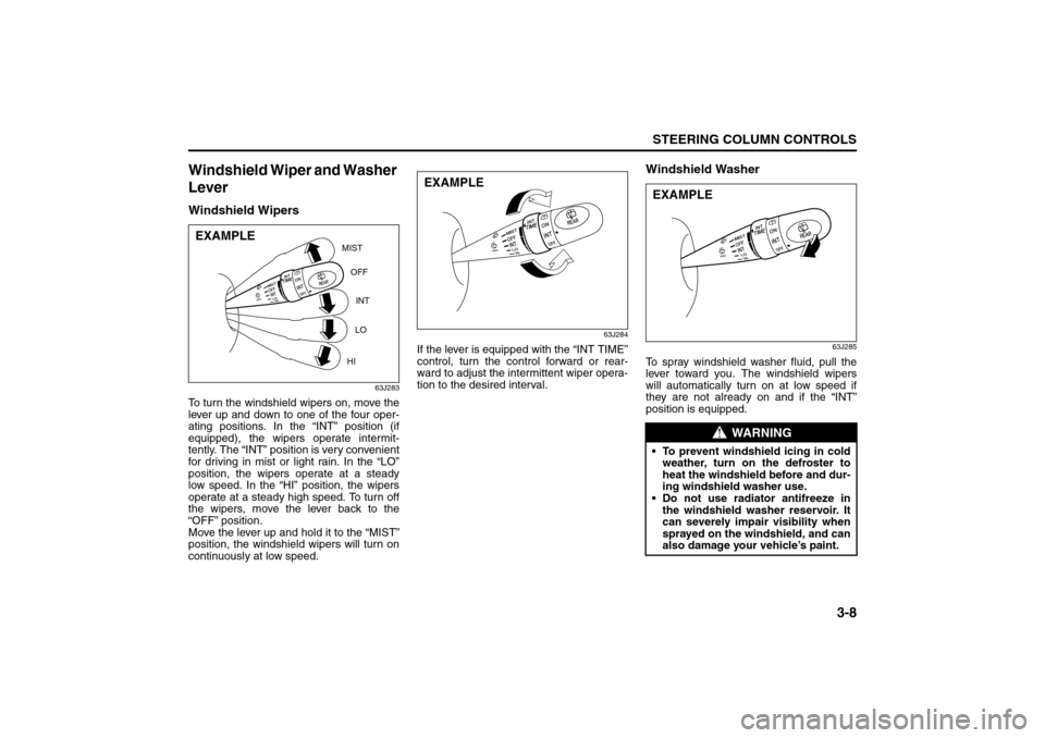
To turn the windshield wipers on, move the
lever up and down to one of the four oper-
ating positions. In the “INT” position (if
equipped), the wipers operate intermit-
tently. The “INT” position is very convenient
for driving in mist or light rain. In the “LO”
position, the wipers operate at a steady
low speed. In the “HI” position, the wipers
operate at a steady high speed. To turn off
the wipers, move the lever back to the
“OFF” position.
Move the lever up and hold it to the “MIST”
position, the windshield wipers will turn on
continuously at low speed.
63J284
If the lever is equipped with the “INT TIME”
control, turn the control forward or rear-
ward to adjust the intermittent wiper opera-
tion to the desired interval.
Windshield Washer
63J285
To spray windshield washer fluid, pull the
lever toward you. The windshield wipers
will automatically turn on at low speed if
they are not already on and if the “INT”
position is equipped.
MIST
OFF
INT
LO
HI
EXAMPLE
EXAMPLE
WARNING
To prevent windshield icing in cold
weather, turn on the defroster to
heat the windshield before and dur-
ing windshield washer use.
Do not use radiator antifreeze in
the windshield washer reservoir. It
can severely impair visibility when
sprayed on the windshield, and can
also damage your vehicle’s paint.EXAMPLE
Windshield Wiper and Washer Lever: 8
Page 70 of 290
3-9STEERING COLUMN CONTROLS
66J22-03E
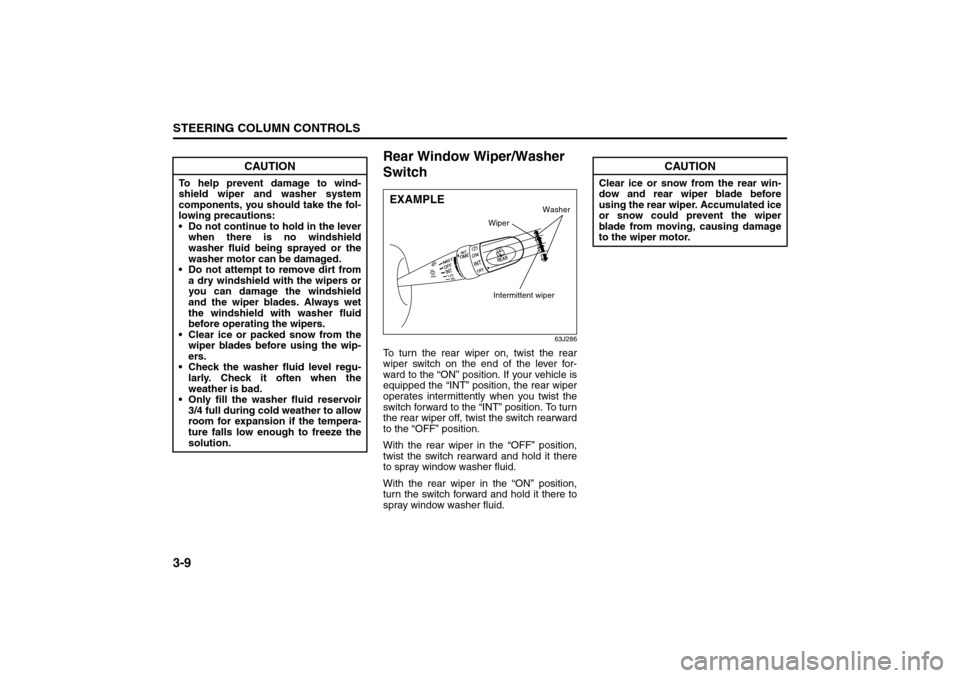
Rear Window Wiper/Washer
Switch
63J286
To turn the rear wiper on, twist the rear
wiper switch on the end of the lever for-
ward to the “ON” position. If your vehicle is
equipped the “INT” position, the rear wiper
operates intermittently when you twist the
switch forward to the “INT” position. To turn
the rear wiper off, twist the switch rearward
to the “OFF” position.
With the rear wiper in the “OFF” position,
twist the switch rearward and hold it there
to spray window washer fluid.
With the rear wiper in the “ON” position,
turn the switch forward and hold it there to
spray window washer fluid.
CAUTION
To help prevent damage to wind-
shield wiper and washer system
components, you should take the fol-
lowing precautions:
Do not continue to hold in the lever
when there is no windshield
washer fluid being sprayed or the
washer motor can be damaged.
Do not attempt to remove dirt from
a dry windshield with the wipers or
you can damage the windshield
and the wiper blades. Always wet
the windshield with washer fluid
before operating the wipers.
Clear ice or packed snow from the
wiper blades before using the wip-
ers.
Check the washer fluid level regu-
larly. Check it often when the
weather is bad.
Only fill the washer fluid reservoir
3/4 full during cold weather to allow
room for expansion if the tempera-
ture falls low enough to freeze the
solution.
EXAMPLE
Wiper
Intermittent wiper
Washer
CAUTION
Clear ice or snow from the rear win-
dow and rear wiper blade before
using the rear wiper. Accumulated ice
or snow could prevent the wiper
blade from moving, causing damage
to the wiper motor.
Windshield Wiper and Washer Lever: 8
Rear Window Wiper/Washer Switch: 8