Trip SUZUKI GRAND VITARA 2008 3.G Owners Manual
[x] Cancel search | Manufacturer: SUZUKI, Model Year: 2008, Model line: GRAND VITARA, Model: SUZUKI GRAND VITARA 2008 3.GPages: 290, PDF Size: 4.99 MB
Page 75 of 290
INSTRUMENT PANEL
4
66J22-03E
60G406
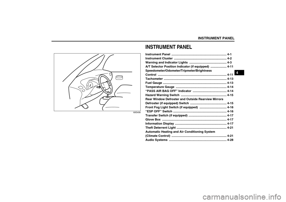
INSTRUMENT PANELInstrument Panel ................................................................. 4-1
Instrument Cluster .............................................................. 4-2
Warning and Indicator Lights ............................................ 4-3
A/T Selector Position Indicator (if equipped) ................... 4-11
Speedometer/Odometer/Tripmeter/Brightness
Control ................................................................................. 4-11
Tachometer .......................................................................... 4-13
Fuel Gauge ........................................................................... 4-13
Temperature Gauge ............................................................ 4-14
“PASS AIR BAG OFF” Indicator ........................................ 4-14
Hazard Warning Switch ...................................................... 4-15
Rear Window Defroster and Outside Rearview Mirrors
Defroster (if equipped) Switch ........................................... 4-15
Front Fog Light Switch (if equipped) ................................ 4-16
“ESP OFF” Switch ............................................................... 4-16
Transfer Switch (if equipped) ............................................. 4-17
Glove Box ............................................................................ 4-17
Information Display ............................................................. 4-17
Theft Deterrent Light ........................................................... 4-21
Automatic Heating and Air Conditioning System
(Climate Control) ................................................................. 4-21
Audio Systems .................................................................... 4-28
Page 77 of 290
4-2
INSTRUMENT PANEL
66J22-03E
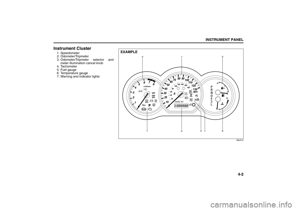
Instrument Cluster1. Speedometer
2. Odometer/Tripmeter
3. Odometer/Tripmeter selector and
meter illumination cancel knob
4. Tachometer
5. Fuel gauge
6. Temperature gauge
7. Warning and indicator lights
66J212
4
72736 15
EXAMPLE
Instrument Cluster: 8
Page 86 of 290
4-11INSTRUMENT PANEL
66J22-03E
A/T Selector Position
Indicator (if equipped)
66J034
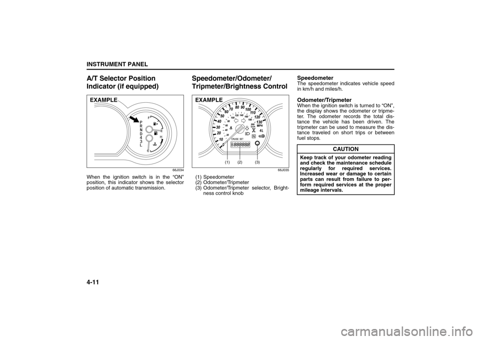
When the ignition switch is in the “ON”
position, this indicator shows the selector
position of automatic transmission.
Speedometer/Odometer/
Tripmeter/Brightness Control
66J035
(1) Speedometer
(2) Odometer/Tripmeter
(3) Odometer/Tripmeter selector, Bright-
ness control knob
SpeedometerThe speedometer indicates vehicle speed
in km/h and miles/h.Odometer/TripmeterWhen the ignition switch is turned to “ON”,
the display shows the odometer or tripme-
ter. The odometer records the total dis-
tance the vehicle has been driven. The
tripmeter can be used to measure the dis-
tance traveled on short trips or between
fuel stops.
EXAMPLE
(1)
(2)
(3)
EXAMPLE
CAUTION
Keep track of your odometer reading
and check the maintenance schedule
regularly for required services.
Increased wear or damage to certain
parts can result from failure to per-
form required services at the proper
mileage intervals.
A/T Selector Position Indicator: 8
Speedometer/Odometer/Trip meter/Meter Illumination
Control: 8
Page 87 of 290
4-12
INSTRUMENT PANEL
66J22-03E
64J049
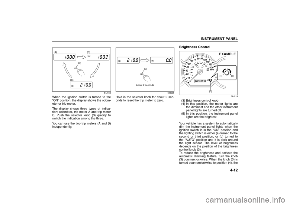
When the ignition switch is turned to the
“ON” position, the display shows the odom-
eter or trip meter.
The display shows three types of indica-
tion; odometer, trip meter A and trip meter
B. Push the selector knob (3) quickly to
switch the indication among the three.
You can use the two trip meters (A and B)
independently.
64J205
Hold in the selector knob for about 2 sec-
onds to reset the trip meter to zero.
Brightness Control
66J213
(3) Brightness control knob
(4) In this position, the meter lights are
the dimmest and the other instrument
panel lights are turned off.
(5) In this position, the instrument panel
lights are the brightest.
Your vehicle has a system to automatically
dim the instrument panel lights when the
ignition switch is in the “ON” position and
the lighting switch is either (a) turned to the
second or third position, or (b) turned to
the “AUTO” position and it is dark around
the light sensor. The level of brightness
depends on the position of the brightness
control knob (3).
To reduce the brightness and activate the
automatic dimming feature, turn the knob
(3) counterclockwise. When the knob (3) is
turned counterclockwise to position (4), the
(3) (A) (B)
(C)
About 2 seconds
(3)
(3)
(5) (4)
EXAMPLE
Speedometer/Odometer/Trip meter/Meter Illumination
Control: 8
Page 88 of 290
4-13INSTRUMENT PANEL
66J22-03E
meter brightness becomes dimmest and
the other instrument panel lights are
turned off.
To brighten the instrument panel lights,
turn the knob (3) clockwise.
To cancel the automatic dimming feature
and maintain full brightness, turn the knob
(3) clockwise to position (5).
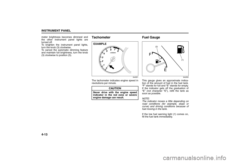
Tachometer
64J051
The tachometer indicates engine speed in
revolutions per minute.
Fuel Gauge
64J052
This gauge gives an approximate indica-
tion of the amount of fuel in the fuel tank.
“F” stands for full and “E” stands for empty.
If the indicator gets off the graduation of
“E” (not character “E”), refill the tank as
soon as possible.
NOTE:
The indicator moves a little depending on
road conditions (for example, slope or
curve) and driving conditions because of
fuel moving in the tank.
If the low fuel warning light (1) comes on,
fill the fuel tank immediately.
CAUTION
Never drive with the engine speed
indicator in the red zone or severe
engine damage can result.EXAMPLE
(1) (2)
Speedometer/Odometer/Trip meter/Meter Illumination Control: 8Tachometer: 8
Fuel Gauge: 8
Page 214 of 290

9-7INSPECTION AND MAINTENANCE
66J22-03E
Maintenance Recommended under Severe Driving ConditionsIf the vehicle is usually used under the conditions corresponding to any severe condition code given below, it is recommended that appli-
cable maintenance operation be performed at the particular interval shown in the chart below.
Severe condition code
A – Repeated short trips
B – Driving on rough and/or muddy roads
C – Driving on dusty roads
D – Driving in extremely cold weather and/or on salted roads
E – Repeated short trips in extremely cold weather
H – Towing a trailer
Severe
Condition CodeMaintenanceMaintenance
OperationMaintenance Interval
A – C D E H Engine oil and oil filter REvery 5000 km (3000 miles)
or 3 months
A B – D – H Exhaust pipes and mountings IEvery 10000 km (6000 miles)
or 6 months
– – C – – – Air cleaner filter element *1IEvery 5000 km (3000 miles)
or 3 months
REvery 25000 km (15000 miles)
or 15 months
– – C – – – Canister air suction filter REvery 100000 km (60000 miles)
or 60 months
ABC– – HBrake discs and pads (front)
Brake drums and shoes (rear)IEvery 10000 km (6000 miles)
or 6 months
– B – D E H Propeller shafts/Drive shafts IEvery 10000 km (6000 miles)
or 6 months
– B – – E H Manual transmission oil REvery 25000 km (15000 miles)
or 15 months
Maintenance Recommended under Severe Driving Condi-
tions: 1, 2, 3, 4, 5, 6, 9, 10
Page 241 of 290

9-34
INSPECTION AND MAINTENANCE
66J22-03E
Steps for Determining Correct Load
Limit
1) Locate the statement “The combined
weight of occupants and cargo shouldnever exceed XXX kg or XXX lbs” on
your vehicle’s placard.
2) Determine the combined weight of the
driver and passengers that will be riding
in your vehicle.
3) Subtract the combined weight of the
driver and passengers from XXX kg or
XXX lbs.
4) The resulting figure equals the available
amount of cargo and luggage load
capacity. For example, if the “XXX”
amount equals 1400 lbs and there will
be five 150 lb passengers in your vehi-
cle, the amount of available cargo and
luggage load capacity is 650 lbs (1400
– 750 (5 x 150) = 650 lbs).
5) Determine the combined weight of lug-
gage and cargo being loaded on the
vehicle. That weight may not safely
exceed the available cargo and luggage
load capacity calculated in Step 4.
6) If your vehicle will be towing a trailer,
load from your trailer will be transferred
to your vehicle. Consult this manual to
determine how this reduces the avail-
able cargo and luggage load capacity of
your vehicle.
Vehicle Loading Example
As an example, suppose that the Tire and
Loading Information label on your vehicle
indicates that your vehicle’s total load
capacity is 950 lbs. If you were to drive
your vehicle with one passenger, and the
total combined weight of you and your pas-
senger was 350 lbs, then the cargo andluggage capacity of your vehicle would be
600 lbs (950 – 350 = 600 lbs).
If you later added 2 more passengers, hav-
ing a combined weight of 325 lbs, the
cargo and luggage capacity of your vehicle
would be reduced from 600 lbs to 275 lbs
(600 – 325 = 275 lbs). As you can see, as
the number and combined weight of vehi-
cle occupants increase, the vehicle’s cargo
and luggage capacity decreases.
Suppose again, that you were to take a trip
in your vehicle with the same three pas-
sengers described above, and you decided
to tow a trailer having a trailer tongue
weight of 75 lbs. The cargo and luggage
capacity would be reduced again, to 200
lbs (275 – 75 = 200 lbs).
Determining Compatibility of Tire and
Vehicle Load Limits
The tires on your vehicle, when they are
inflated to the recommended tire inflation
pressure, have a load-carrying capacity
that is greater than the load that will be on
the tires when the vehicle is at its GVWR
or GAWR limit. Never use replacement
tires that have a load-carrying capacity
less than the original tires on your vehicle.
Tire load-carrying capacity information is
molded into the tire sidewall typically
shown as “Max. Load”. Use of replacement
tires with a lower load-carrying capacity
than the original tires, or failure to keep the
tires inflated to recommended tire pres-
sure, may reduce the GVWR or GAWR
limit of your vehicle.
WARNING
Never overload your vehicle. Over-
loading your vehicle can cause dam-
age to your tires and lead to poor
steering and braking which can result
in an accident. The gross vehicle
weight (sum of the weights of the
loaded vehicle, driver and passen-
gers) must never exceed the Gross
Vehicle Weight Rating (GVWR) listed
on the Safety Certification Label. In
addition, never distribute a load so
that the weight on either the front or
rear axle exceeds the Gross Axle
Weight Rating (GAWR) listed on the
Safety Certification Label.
WARNING
Always distribute cargo evenly.
To avoid personal injury or damage
to your vehicle, always secure
cargo to prevent it from shifting if
the vehicle moves suddenly.
Place heavier objects on the floor
and as far forward in the cargo area
as possible. Never pile cargo
higher than the top of the seat-
backs.
Fuses: 7
Page 287 of 290

15-5
INDEX66J22-03E
Tire Rotation
........................................................................9-29
Tire Sidewall Labeling
.........................................................9-24
Tire Size
................................................................................9-25
Tires
......................................................................................9-24
Towing a Disabled Vehicle
.................................................10-4
Towing Your Vehicle (recreational towing)
.......................8-7
Traction Control System
.....................................................6-18
Trailer Towing
......................................................................8-2
Transfer Position Indicator Light
.......................................4-10
Transfer Switch
....................................................................4-17
Tripmeter
..............................................................................4-11
Troubleshooting
..................................................................4-53
Turn Signal Indicators
.........................................................4-9
Turn Signal Operation .........................................................3-7
UUnderfloor Bins
...................................................................5-23
Uniform Tire Quality Grading
.............................................9-28
Using the Transfer Switch
..................................................6-7
Using the Transmission
......................................................6-5
VVehicle Cleaning
..................................................................11-3
Vehicle Identification Number
............................................12-1
Vehicle Loading
........................................................... 8-1
, 9-33
Vehicle With Keyless Start System
............................ 3-2
, 6-3
Vehicle Without Keyless Start System
..............................3-1
WWarning and Indicator Lights
.............................................4-3
Warranties
............................................................................12-2
Washing
................................................................................11-4
Waxing ..................................................................................11-4
Windows ...............................................................................2-14Windshield Washer Fluid
................................................... 9-19
Windshield Wiper and Washer Lever
................................ 3-8
Wiper Blades
....................................................................... 9-44