power steering SUZUKI GRAND VITARA 2008 3.G Owners Manual
[x] Cancel search | Manufacturer: SUZUKI, Model Year: 2008, Model line: GRAND VITARA, Model: SUZUKI GRAND VITARA 2008 3.GPages: 290, PDF Size: 4.99 MB
Page 65 of 290
3-4
STEERING COLUMN CONTROLS
66J22-03E
64J216
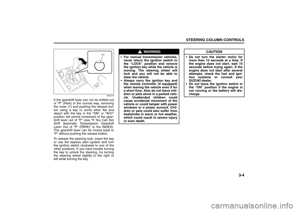
If the gearshift lever can not be shifted out
of “P” (Park) in the normal way, removing
the cover (1) and pushing the release but-
ton using a key or some other flat end
object with the key in the “ON” or “ACC”
position will permit movement of the gear-
shift lever out of “P” (see “If You Can Not
Shift Automatic Transmission Gearshift
Lever Out of “P” (PARK)” in the INDEX).
The gearshift lever can be moved back to
“P” without pushing the release button.
To release the steering lock, insert the key
or use the keyless start system and turn
the ignition switch clockwise to one of the
other positions. If you have trouble turning
the key to unlock the steering, try turning
the steering wheel slightly to the right or
left while turning the key.
(1)
WARNING
For manual transmission vehicles,
never return the ignition switch to
the “LOCK” position and remove
the ignition key while the vehicle is
moving. The steering wheel will
lock and you will not be able to
steer the vehicle.
Always carry the ignition key and
the remote controller (if equipped)
when leaving the vehicle even if for
a short time. Also do not leave chil-
dren or pets alone in a parked vehi-
cle. Unattended children could
cause accidental movement of the
vehicle or could tamper with power
windows or a power sunroof. Chil-
dren or pets could also suffer from
heatstroke in warm or hot weather,
which could result in severe injury
or even death.
CAUTION
Do not turn the starter motor for
more than 15 seconds at a time. If
the engine does not start, wait 15
seconds before trying again. If the
engine does not start after several
attempts, check the fuel and igni-
tion systems or consult your
SUZUKI dealer.
Do not leave the ignition switch in
the “ON” position if the engine is
not running or the battery will dis-
charge.
Ignition Switch: 8, 10
Page 161 of 290
6-2
OPERATING YOUR VEHICLE
66J22-03E
Daily Inspection ChecklistBefore Driving1) Make sure that windows, mirrors, lights
and reflectors are clean and unob-
structed.
2) Visually check the tires for the following
points:
– the depth of the tread groove
– abnormal wear, cracks and damage
– loose wheel nuts
– existence of foreign material such as
nails, stones, etc.
Refer to “Tires” in “INSPECTION AND
MAINTENANCE” section for details.
3) Look for fluid, oil leaks.
NOTE:
It is normal for water to drip from the air
conditioning system after use.
4) Make sure the hood is fully closed and
latched.
5) Check the headlights, turn signal lights,
brake lights and horn for proper opera-
tion.
6) Lock all doors.
7) Adjust the seat and adjustable head
restraints (if equipped).
8) Check the brake pedal and the parking
brake lever.
9) Adjust the mirrors.
10)Make sure that you and all passengers
have properly fastened your seat belts.11)Make sure that all warning lights come
on as the key is turned to the “ON” or
“START” position.
12)Check all gauges.
13)Make sure that the BRAKE SYSTEM
WARNING light turns off when the
parking brake is released.
Once a week, or each time you fill your fuel
tank, perform the following under-hood
checks:
1) Engine oil level
2) Coolant level
3) Brake fluid level
4) Power steering (if equipped) fluid level
5) Windshield washer fluid level
6) Hood latch operation
Pull the hood release handle inside the
vehicle. Make sure that you cannot
open the hood all the way without
releasing the secondary latch. Be sure
to close the hood securely after check-
ing for proper latch operation. See the
item “All Latches, Hinges and Locks” of
“CHASSIS AND BODY” in the “Periodic
Maintenance Schedule” in the
“INSPECTION AND MAINTENANCE”
section for lubrication schedule.
Starting the EngineBefore Starting the Engine1) Make sure the parking brake is set fully.
2) Manual Transmission – Shift into “N”
(Neutral) and depress the clutch pedal
all the way to the floor.
Hold it while starting the engine.
Automatic Transmission – If the gear-
shift lever is not in “P” (Park) position,
shift into “P”. (If you need to re-start the
engine while the vehicle is moving, shift
into “N”.)
NOTE:
The engine of manual transmission vehicle
will not start unless the clutch pedal is
depressed.
NOTE:
Automatic transmission vehicles have a
starter interlock device which is designed
to keep the starter from operating if the
transmission is in any of the drive posi-
tions.
WARNING
Make sure the hood is fully closed
and latched before driving. If it is not,
it can fly up unexpectedly during
driving, obstructing your view and
resulting in an accident.
WARNING
Make sure that the parking brake is
set fully and the transmission is in
Neutral (or Park for vehicles with an
automatic transmission) before
attempting to start the engine.
Daily Inspection Checklist: NO
Starting the Engine: 1
Page 175 of 290
6-16
OPERATING YOUR VEHICLE
66J22-03E
Power Assisted BrakesYour vehicle has power assisted brakes. If
power assistance is lost due to a stalled
engine or other failures, the system is still
fully operational on reserve power and you
can bring the vehicle to a complete stop by
pressing the brake pedal once and holding
it down. The reserve power is partly used
up when you depress the brake pedal and
reduces each time the pedal is pressed.
Apply smooth and even pressure to the
pedal. Do not pump the pedal.
Brake Assist SystemWhen you slam the brakes on, the brake
assist system judges as an emergency
stop and provides more powerful braking
for a driver who cannot hold down the
brake pedal firmly.
NOTE:
If you depress the brakes forcefully, you
may hear a clicking sound in the brake
pedal. This is normal and indicates that the
brake assist system is activated properly.
Anti-Lock Brake System (ABS)ABS will help you avoid skidding by elec-
tronically controlling braking pressure. It
will also help you maintain steering control
when braking on slippery surfaces or when
braking hard.
The ABS works automatically, so you do
not need any special braking technique.
Just push the brake pedal down without
pumping. The ABS will operate whenever it
senses that the wheels are locking up.
You may feel the brake pedal pulsate while
the ABS is operating.
NOTE:
The ABS will not work if vehicle speed is
under 5 – 6 km/h (3 – 4 mph).
WARNING
If water gets into the brake drums,
brake performance may become poor
and unpredictable. After driving
through water or washing the under-
side of the vehicle, test the brakes
while driving at a slow speed to see if
they have maintained their normal
effectiveness. If the brakes are less
effective than normal, dry them by
repeatedly applying the brakes while
driving slowly until the brakes have
regained their normal effectiveness.
WARNING
Even without reserve power in the
brake system, you can still stop the
vehicle by pressing the brake pedal
harder than normally required. How-
ever, the stopping distance may be
longer.
Using the Transfer Switch: 10
Braking: 6
Page 177 of 290
6-18
OPERATING YOUR VEHICLE
66J22-03E
How the ABS WorksA computer continuously monitors wheel
speed. The computer compares the
changes in wheel speed when braking. If
the wheels slow suddenly, indicating a
skidding situation, the computer will
change braking pressure several times
each second to prevent the wheels from
locking. When you start your vehicle or
when you accelerate after a hard stop, you
may hear a momentary motor or clicking
sound as the system resets or checks
itself.
Electronic Stability Program
(ESP
®)
ESP
® is a registered trademark of
DaimlerChrysler AG.
The Electronic Stability Program (ESP
®)
helps to control the vehicle during corner-
ing if the vehicle is understeering or over-
steering. It also assists you in maintaining
traction while accelerating on loose or slip-
pery road surfaces. It does this by regulat-
ing the engine’s output, and by selectively
applying the brakes. In addition, ESP®
helps to avoid skidding by controlling brak-
ing pressure.The ESP
® has the following three systems:
Stability Control SystemThe vehicle stability control system helps
provide integrated control of systems such
as anti-lock brakes, traction control, engine
control, etc. This system automatically
controls the brakes and engine to help pre-
vent the vehicle from skidding when cor-
nering on a slippery road surface or when
turning the steering wheel abruptly.Traction Control SystemThe traction control system automatically
helps prevent the spinning of wheels when
the vehicle is started or accelerated on
slippery road surfaces. The system oper-
ates only if it senses that some of the
wheels are spinning or beginning to lose
traction. When this happens, the system
operates the front or rear brakes and
reduces engine power to limit wheel spin.
NOTE:
You may hear a clicking sound in the
engine compartment for a few seconds
when you start the engine or just after the
vehicle begins to move. This means that
the above systems are in the self-check
mode. This sound does not indicate a mal-
function.
WARNING
The ABS may not work properly if
tires or wheels other than those
specified in the owner’s manual are
used. This is because the ABS works
by comparing changes in wheel
speed. When replacing tires or
wheels, use only the size and type
specified in this owner’s manual.
WARNING
The ESP
® cannot enhance the vehi-
cle’s driving stability in all situations
and does not control your vehicle’s
entire braking system. The ESP
® can-
not prevent accidents, including
those resulting from excessive speed
in turns, or hydroplaning. Only a safe
and attentive driver can prevent acci-
dents. The capabilities of an ESP
®-
equipped vehicle must never be used
as a substitute for careful driving.
Braking: 6
Page 212 of 290
9-5INSPECTION AND MAINTENANCE
66J22-03E
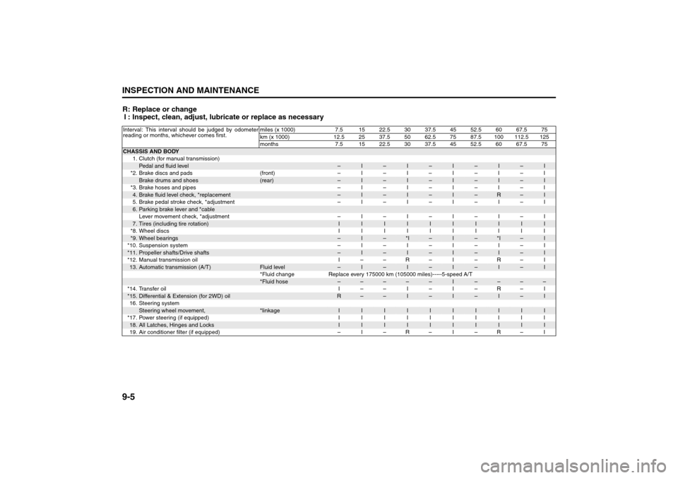
R: Replace or change
I : Inspect, clean, adjust, lubricate or replace as necessaryInterval: This interval should be judged by odometer
reading or months, whichever comes first.miles (x 1000) 7.5 15 22.5 30 37.5 45 52.5 60 67.5 75
km (x 1000) 12.5 25 37.5 50 62.5 75 87.5 100 112.5 125
months 7.5 15 22.5 30 37.5 45 52.5 60 67.5 75CHASSIS AND BODY
1. Clutch (for manual transmission)
Pedal and fluid level
–
I
–
I
–
I
–
I
–
I
*2. Brake discs and pads (front) – I – I – I – I – I
Brake drums and shoes
(rear)
–
I
–
I
–
I
–
I
–
I
*3. Brake hoses and pipes – I – I – I – I – I
4.Brake fluid level check, *replacement
–
I
–
I
–
I
–
R
–
I
5. Brake pedal stroke check, *adjustment – I – I – I – I – I
6.Parking brake lever and *cableLever movement check, *adjustment – I – I – I – I – I7.Tires (including tire rotation)
I
I
I
I
I
I
I
I
I
I
*8. Wheel discs I I I I I I I I I I
*9.
Wheel bearings
–
I
–
*I
–
I
–
*I
–
I
*10. Suspension system – I – I – I – I – I
*11.
Propeller shafts/Drive shafts
–
I
–
I
–
I
–
I
–
I
*12. Manual transmission oil I – – R – I – R – I
13.
Automatic transmission (A/T)
Fluid level
–
I
–
I
–
I
–
I
–
I
*Fluid change Replace every 175000 km (105000 miles)-----5-speed A/T
*Fluid hose
–
–
–
–
–
I
–
–
–
–
*14. Transfer oil I – – I – I – R – I
*15.
Differential & Extension (for 2WD) oil
R
–
–
I
–
I
–
I
–
I
16. Steering system
Steering wheel movement,
*linkage
I
I
I
I
I
I
I
I
I
I
*17. Power steering (if equipped) I I I I I I I I I I
18.
All Latches, Hinges and Locks
I
I
I
I
I
I
I
I
I
I
19. Air conditioner filter (if equipped) – I – R – I – R – I
Periodic Maintenance Schedule: 1, 2, 3, 4, 5, 6, 9, 10
Page 213 of 290
9-6
INSPECTION AND MAINTENANCE
66J22-03E
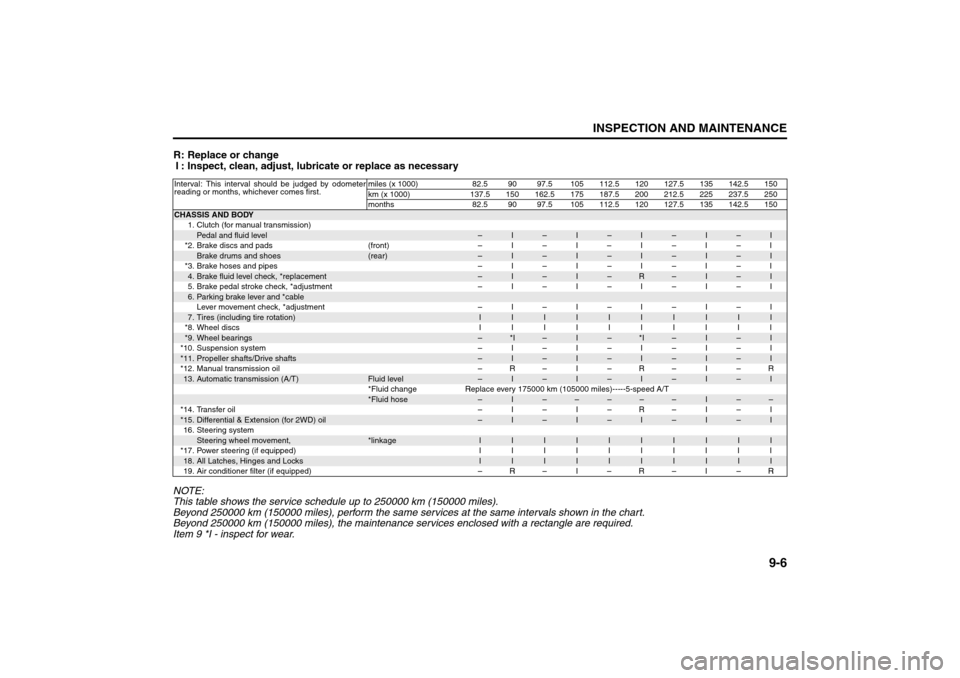
R: Replace or change
I : Inspect, clean, adjust, lubricate or replace as necessary
NOTE:
This table shows the service schedule up to 250000 km (150000 miles).
Beyond 250000 km (150000 miles), perform the same services at the same intervals shown in the chart.
Beyond 250000 km (150000 miles), the maintenance services enclosed with a rectangle are required.
Item 9 *I - inspect for wear.Interval: This interval should be judged by odometer
reading or months, whichever comes first.miles (x 1000) 82.5 90 97.5 105 112.5 120 127.5 135 142.5 150
km (x 1000) 137.5 150 162.5 175 187.5 200 212.5 225 237.5 250
months 82.5 90 97.5 105 112.5 120 127.5 135 142.5 150CHASSIS AND BODY
1. Clutch (for manual transmission)
Pedal and fluid level
–
I
–
I
–
I
–
I
–
I
*2. Brake discs and pads (front) – I – I – I – I – I
Brake drums and shoes
(rear)
–
I
–
I
–
I
–
I
–
I
*3. Brake hoses and pipes – I – I – I – I – I
4.Brake fluid level check, *replacement
–
I
–
I
–
R
–
I
–
I
5. Brake pedal stroke check, *adjustment – I – I – I – I – I
6.Parking brake lever and *cableLever movement check, *adjustment – I – I – I – I – I7.Tires (including tire rotation)
I
I
I
I
I
I
I
I
I
I
*8. Wheel discs I I I I I I I I I I
*9.
Wheel bearings
–
*I
–
I
–
*I
–
I
–
I
*10. Suspension system – I – I – I – I – I
*11.
Propeller shafts/Drive shafts
–
I
–
I
–
I
–
I
–
I
*12. Manual transmission oil – R – I – R – I – R
13.
Automatic transmission (A/T)
Fluid level
–
I
–
I
–
I
–
I
–
I
*Fluid change Replace every 175000 km (105000 miles)-----5-speed A/T
*Fluid hose
–
I
–
–
–
–
–
I
–
–
*14. Transfer oil – I – I – R – I – I
*15.
Differential & Extension (for 2WD) oil
–
I
–
I
–
I
–
I
–
I
16. Steering system
Steering wheel movement,
*linkage
I
I
I
I
I
I
I
I
I
I
*17. Power steering (if equipped) I I I I I I I I I I
18.
All Latches, Hinges and Locks
I
I
I
I
I
I
I
I
I
I
19. Air conditioner filter (if equipped) – R – I – R – I – R
Periodic Maintenance Schedule: 1, 2, 3, 4, 5, 6, 9, 10
Page 216 of 290

9-9INSPECTION AND MAINTENANCE
66J22-03E
Drive BeltMake sure the drive belt tension is correct.
If the belt is too loose, insufficient battery
charging, engine overheating, poor power
steering, poor air conditioning or excessive
belt wear can result. When you press the
belt with your thumb midway between the
pulleys, there should be a deflection
according to the following chart.
The belts should also be examined to
ensure that they are not damaged.
If you need to replace or adjust the belt
have it done by your SUZUKI dealer.
52D029
Engine Oil and FilterSpecified Oil
52D083
(1) Preferred
Use engine oil with the American Petro-
leum Institute Certified For Gasoline
Engines “Starburst” symbol.
Select the appropriate oil viscosity accord-
ing to the above chart.
We highly recommend you use SAE 5W-
30 oil.
WARNING
When the engine is running, keep
hands, hair, clothing, tools, etc. away
from the moving fan and drive belts.
DEFL: 4 – 7 mm (0.16 – 0.28 in.) DEFL: 9 – 11 mm (0.35 – 0.43 in.)
PS
GE
AC
→: 100 N (22 lbs, 10 kg) press
GE: Generator
DEFL: Deflection
PS: Power steering pump
AC: Air conditioner compressor
CAUTION
Failure to use the recommended oil
can result in engine damage.C
Fo o-30
-22-20
-4-10
14 32 50 68 86 104010203040
10W-30
(1)
5W-30
Temperature
EXAMPLE
“Starburst”
Drive Belt: 1, 2
Engine Oil and Filter: 1, 2
Page 231 of 290
9-24
INSPECTION AND MAINTENANCE
66J22-03E
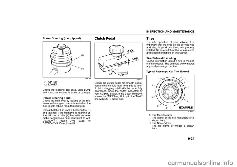
Power Steering (if equipped)
64J155
(1) UPPER
(2) LOWER
Check the steering box case, vane pump
and hose connections for leaks or damage.Power Steering FluidCheck the fluid level by looking at the res-
ervoir in the engine compartment when the
fluid is cold (about room temperature).
Check that the fluid level is between the (1)
and (2) lines. If the fluid level is near the (2)
line, fill it up to the (1) line with an auto-
matic transmission fluid equivalent to ATF
DEXRON
®-II (Esso JWS 2326) or
DEXRON®-III. Do not overfill.
Clutch Pedal
64J154
Check the clutch pedal for smooth opera-
tion and clutch fluid level from time to time.
If clutch dragging is felt with the pedal fully
depressed, have the clutch inspected by
your SUZUKI dealer. If the clutch fluid level
is near the “MIN” line, fill it up to the “MAX”
line with DOT3 brake fluid.
TiresFor safe operation of your vehicle, it is
important that the tires be the correct type
and size, in good condition, and properly
inflated. Be sure to follow the requirements
and recommendations in this section.Tire Sidewall LabelingUseful information about a tire is molded
into its sidewall. The example below shows
a typical passenger car tire.
Typical Passenger Car Tire Sidewall
67D027
A. Tire Manufacturer
The name of the tire manufacturer is
shown here.
B. Tire Name/Model
The tire name or model is shown
here.
(1)
(2)
AH B
G
E
FD
J I
C
EXAMPLE
Tires: 6
Page 239 of 290
9-32
INSPECTION AND MAINTENANCE
66J22-03E
Snow TiresYour vehicle is equipped with all-season
tires which are designed for use in summer
and most winter conditions. For improved
traction in severe winter conditions,
SUZUKI recommends mounting radial
snow tires on all four wheels. Snow tires
must be the same size as the standard
tires. Also be sure to use the tires of the
same type and brand on all four wheels of
your vehicle.
GLOSSARY OF TIRE TERMINOL-
OGYAccessory Weight – the combined weight
(in excess of those standard items which
may be replaced) of automatic transmis-
sion, power steering, power brakes, power
windows, power seats, radio, and heater,
to the extent that these items are available
as factory-installed equipment (whether
installed or not).
Cold Tire Inflation Pressure – the pressure
in a tire that has been driven less than 1
mile or has been standing for three hours
or more.
Curb Weight – the weight of a motor vehi-
cle with standard equipment including the
maximum capacity of fuel, oil, and coolant,
and, if so equipped, air conditioning and
additional weight optional engine.
Intended Outboard Sidewall – (1) the side-
wall that contains a whitewall, bears white
lettering or bears manufacturer, brand,
and/or model name molding that is higher
or deeper than the same molding on the
other sidewall of the tire, or (2) the outward
facing sidewall of an asymmetrical tire that
has a particular side that must always face
outward when mounted on a vehicle.
Maximum Inflation Pressure – the maxi-
mum cold inflation pressure a tire is
designed to support in normal service.
Maximum Loaded Vehicle Weight – the
sum of curb weight, accessory weight,vehicle capacity weight (total load capac-
ity), and production options weight.
Normal Occupant Weight – 68 kilograms
times the number of occupants specified in
the second column of Table 1 (shown
below).
Occupant distribution – distribution of
occupants in a vehicle as specified in the
third column of Table 1 (shown below).
Production Options Weight – the combined
weight of those installed regular production
options weighing over 2.3 kilograms in
excess of those standard items which they
replace, not previously considered in curb
weight or accessory weight, including
heavy duty brakes, ride levelers, roof rack,
heavy duty battery, and special trim.
Recommended Inflation Pressure – the
cold tire inflation pressure recommended
by a manufacturer.
Rim – metal support for a tire or tire and
tube assembly upon which the tire beads
are seated.
Vehicle Capacity Weight – the rated cargo
and luggage load plus 68 kilograms (150
lbs) times the vehicle’s designated seating
capacity.
Vehicle Maximum Load on the Tire – the
load on an individual tire that is determined
by distributing to each axle its share of the
maximum loaded vehicle weight and divid-
ing by two.
WARNING
(Continued)
Replace the spare tire with a new
one as soon as the tread wear indi-
cator appears.
When replacing the spare tire, use
a replacement tire with the exact
same size and construction.
Battery: 9
Fuses: 7
Page 286 of 290
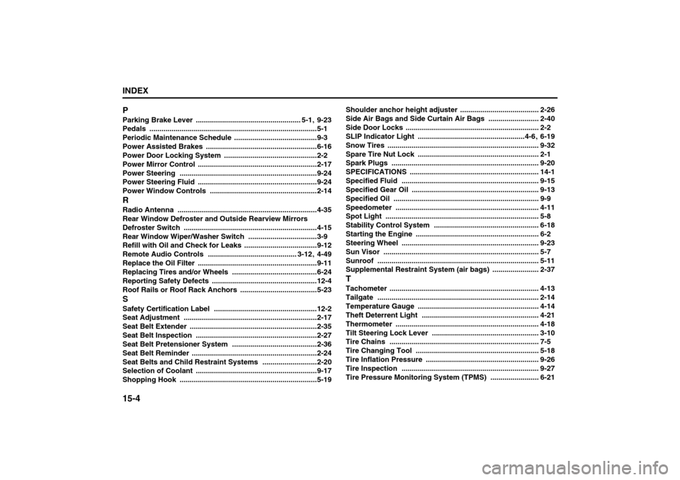
15-4INDEX
66J22-03E
PParking Brake Lever
.................................................... 5-1
, 9-23
Pedals
...................................................................................5-1
Periodic Maintenance Schedule
.........................................9-3
Power Assisted Brakes
.......................................................6-16
Power Door Locking System
..............................................2-2
Power Mirror Control
...........................................................2-17
Power Steering
....................................................................9-24
Power Steering Fluid
...........................................................9-24
Power Window Controls
.....................................................2-14
RRadio Antenna
.....................................................................4-35
Rear Window Defroster and Outside Rearview Mirrors
Defroster Switch ..................................................................4-15
Rear Window Wiper/Washer Switch
..................................3-9
Refill with Oil and Check for Leaks ....................................9-12
Remote Audio Controls
............................................ 3-12
, 4-49
Replace the Oil Filter
...........................................................9-11
Replacing Tires and/or Wheels
..........................................6-24
Reporting Safety Defects
....................................................12-4
Roof Rails or Roof Rack Anchors
......................................5-23
SSafety Certification Label
...................................................12-2
Seat Adjustment
..................................................................2-17
Seat Belt Extender ...............................................................2-35
Seat Belt Inspection ............................................................2-27
Seat Belt Pretensioner System
..........................................2-36
Seat Belt Reminder
..............................................................2-24
Seat Belts and Child Restraint Systems
...........................2-20
Selection of Coolant
............................................................9-17
Shopping Hook
....................................................................5-19Shoulder anchor height adjuster
....................................... 2-26
Side Air Bags and Side Curtain Air Bags
......................... 2-40
Side Door Locks
.................................................................. 2-2
SLIP Indicator Light
.....................................................4-6
, 6-19
Snow Tires
........................................................................... 9-32
Spare Tire Nut Lock
............................................................ 2-1
Spark Plugs
......................................................................... 9-20
SPECIFICATIONS
................................................................ 14-1
Specified Fluid
.................................................................... 9-15
Specified Gear Oil ............................................................... 9-13
Specified Oil
........................................................................ 9-9
Speedometer ....................................................................... 4-11
Spot Light
............................................................................ 5-8
Stability Control System
.................................................... 6-18
Starting the Engine
............................................................. 6-2
Steering Wheel
.................................................................... 9-23
Sun Visor
............................................................................. 5-7
Sunroof
................................................................................ 5-11
Supplemental Restraint System (air bags)
....................... 2-37
TTachometer
.......................................................................... 4-13
Tailgate
................................................................................ 2-14
Temperature Gauge
............................................................ 4-14
Theft Deterrent Light .......................................................... 4-21
Thermometer
....................................................................... 4-18
Tilt Steering Lock Lever
..................................................... 3-10
Tire Chains
.......................................................................... 7-5
Tire Changing Tool
............................................................. 5-18
Tire Inflation Pressure ........................................................ 9-26
Tire Inspection
.................................................................... 9-27
Tire Pressure Monitoring System (TPMS)
........................ 6-21