engine SUZUKI GRAND VITARA 2011 Owners Manual
[x] Cancel search | Manufacturer: SUZUKI, Model Year: 2011, Model line: GRAND VITARA, Model: SUZUKI GRAND VITARA 2011Pages: 337, PDF Size: 6.21 MB
Page 305 of 337
8-6
EMERGENCY SERVICE
79K21-03E
64J196
Snow TiresYour vehicle is equipped with all-season
tires which are designed for use in summer
and most winter conditions. For improved
traction in severe winter conditions,
SUZUKI recommends mounting radial
snow tires on all four wheels. Snow tires
must be the same size as the standard
tires. Also be sure to use the tires of the
same type and brand on all four wheels of
your vehicle.
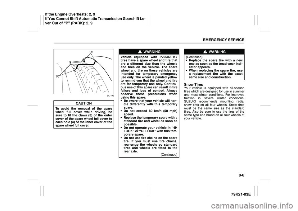
CAUTION
To avoid the removal of the spare
wheel full cover while driving, be
sure to fit the claws (3) of the outer
cover of the spare wheel full cover to
each hole (4) of the inner cover of the
spare wheel full cover.
(3)
(4)
WARNING
Vehicle equipped with P225/65R17
tires have a spare wheel and tire that
are a different size than the wheels
and tires on the vehicle. The spare
wheel and tire on these vehicles are
intended for temporary emergency
use only. The wheel is painted yellow
to remind you that the wheel and tire
are for temporary use only. Continu-
ous use of this spare can result in tire
failure and loss of control. Always
observe these precautions when
using this spare:
Be aware that your vehicle will han-
dle differently with this temporary
spare.
Do not exceed 80 km/h (50 mph)
speed.
Replace the temporary spare with a
standard tire and wheel as soon as
possible.
Do not operate your vehicle in “4H
LOCK” or “4L LOCK” with this tem-
porary spare.
Do not use tire chains on the spare
tire. If you must use tire chains,
rearrange the wheels so standard
tires and wheels are fitted to the
rear axle.
(Continued)
WARNING
(Continued)
Replace the spare tire with a new
one as soon as the tread wear indi-
cator appears.
When replacing the spare tire, use
a replacement tire with the exact
same size and construction.
If the Engine Overheats: 2, 9
If You Cannot Shift Automatic Transmission Gearshift Le-
ver Out of “P” (PARK): 2, 9
Page 306 of 337
8-7EMERGENCY SERVICE
79K21-03E
Jump Starting Instructions
When jump starting your vehicle, use
the following procedure:
60A269
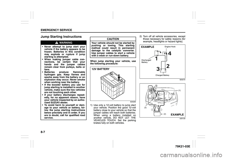
1) Use only a 12-volt battery to jump start
your vehicle. Position the good 12-volt
battery close to your vehicle so that the
jumper cables will reach both batteries.
When using a battery installed on
another vehicle, DO NOT LET THE
VEHICLES TOUCH. Set the parking
brakes fully on both vehicles.2) Turn off all vehicle accessories, except
those necessary for safety reasons (for
example, headlights or hazard lights).
60A270
52D129
WARNING
Never attempt to jump start your
vehicle if the battery appears to be
frozen. Batteries in this condition
may explode or rupture if jump
starting is attempted.
When making jumper cable con-
nections, be certain that your
hands and the jumper cables
remain clear from pulleys, belts or
fans.
Batteries produce flammable
hydrogen gas. Keep flames and
sparks away from the battery or an
explosion may occur. Never smoke
when working near the battery.
If the booster battery you use for
jump starting is installed in another
vehicle, make sure the two vehicles
are not touching each other.
If your battery discharges repeat-
edly, for no apparent reason, have
your vehicle inspected by an autho-
rized SUZUKI dealer.
To avoid harm to yourself or dam-
age to your vehicle or battery, fol-
low the jump starting instructions
below precisely and in order. If you
are in doubt, call for qualified road
service.
CAUTION
Your vehicle should not be started by
pushing or towing. This starting
method could result in permanent
damage to the catalytic converter.
Use jumper cables to start a vehicle
with a weak or run-down battery.12V BATTERY
EXAMPLE
Engine Hook
Charged Battery
Discharged
Battery
EXAMPLE
Page 307 of 337
8-8
EMERGENCY SERVICE
79K21-03E
3) Make jumper cable connections as fol-
lows:
1. Connect one end of the first jumper
cable to the positive (+) terminal of
the discharged battery (1).
2. Connect the other end to the positive
(+) terminal of the booster battery
(2).
3. Connect one end of the second
jumper cable to the negative (–) ter-
minal of the booster battery (2).
4. Make the final connection to an
unpainted, heavy metal part (i.e.
engine hook (3)) of the engine of the
vehicle with the discharged battery
(1).
4) If the booster battery you are using is
installed on another vehicle, start the
engine of the vehicle with the booster
battery. Run the engine at moderate
speed.
5) Start the engine of the vehicle with the
discharged battery.
6) Remove the jumper cables in the exact
reverse order in which you connected
them.
Towing a Disabled VehicleEmergency TowingIf your vehicle is disabled, it may be towed
by a tow truck using one of the following
methods:
1) Tow the vehicle with two wheels lifted
by the tow truck and the other two
wheels on a towing dolly.
2) Use the appropriate towing method
specified for your vehicle in the “Towing
Your Vehicle (recreational towing)” sec-
tion, but with the wheels lifted by the
tow truck instead of on a towing dolly.
Be sure to carefully follow the specific
instructions provided in the “Towing
Your Vehicle (recreational towing)” sec-
tion.
If the Starter Does Not
Operate1) Try turning the ignition switch to the
“START” position with the headlights
turned on to determine the battery con-
dition. If the headlights go excessively
dim or go off, it usually means that
either the battery has run down or bat-
tery terminal contact is poor. Recharge
the battery or correct battery terminal
contact if necessary.
2) If the headlights remain bright, check
the fuses. If the reason for failure of the
starter is not obvious, there may be a
major electrical problem. Have the vehi-
cle inspected by your authorized
SUZUKI dealer.
WARNING
Never connect the jumper cable
directly to the negative (–) terminal of
the discharged battery, or an explo-
sion may occur.
CAUTION
If vehicle damage (such as steering
or drivetrain damage, inability to
operate free axle mechanism, etc.)
prevent normal use of the towing pro-
cedures for your vehicle described in
the “Towing Your Vehicle (recre-
ational towing)” section, have your
vehicle towed with two wheels lifted
by the tow truck and the other two
wheels on a towing dolly.
Page 308 of 337
8-9EMERGENCY SERVICE
79K21-03E
If the Engine is FloodedIf the engine is flooded with gasoline, it
may be hard to start. If this happens, press
the accelerator pedal all the way to the
floor and hold it there while cranking the
engine. (Do not operate the starter motor
for more than 15 seconds).
If the Engine OverheatsThe engine could overheat temporarily
under severe driving conditions. If the
engine coolant temperature gauge indi-
cates overheating during driving:
1) Turn off the air conditioner, if equipped.
2) Take the vehicle to a safe place and
park.
3) Let the engine run at normal idle speed
for a few minutes until the indicator is
within the normal, acceptable tempera-
ture range shown by the white band
between “H” and “C”.If the temperature indication does not
come down to within the normal, accept-
able range:
1) Turn off the engine and check that the
water pump belt and pulleys are not
damaged or slipping. If any abnormality
is found, correct it.
2) Check the coolant level in the reservoir.
If it is found to be lower than the “LOW”
line, look for leaks at the radiator, water
pump and radiator and heater hoses. If
you locate any leaks that may have
caused the overheating, do not run the
engine until these problems have been
corrected.
3) If you do not find a leak, carefully add
coolant to the reservoir and then the
radiator, if necessary. (Refer to “Engine
Coolant” in the “INSPECTION AND
MAINTENANCE” section.)
WARNING
If you see or hear escaping steam,
stop the vehicle in a safe place and
immediately turn off the engine to let
it cool. Do not open the hood when
steam is present. When the steam
can no longer be seen or heard, open
the hood to see if the coolant is still
boiling. If it is, you must wait until it
stops boiling before you proceed.
Also, be careful not to touch hot
engine parts (radiator, water hoses,
engine etc.).
Page 309 of 337
8-10
EMERGENCY SERVICE
79K21-03E
66J191
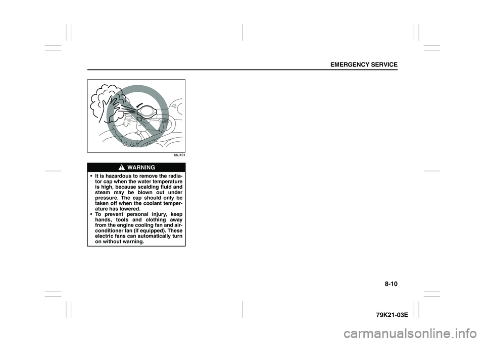
WARNING
It is hazardous to remove the radia-
tor cap when the water temperature
is high, because scalding fluid and
steam may be blown out under
pressure. The cap should only be
taken off when the coolant temper-
ature has lowered.
To prevent personal injury, keep
hands, tools and clothing away
from the engine cooling fan and air-
conditioner fan (if equipped). These
electric fans can automatically turn
on without warning.
Page 315 of 337
9-4
APPEARANCE CARE
79K21-03E
Cleaning the Exterior
WashingWhen washing the vehicle, follow the
instructions below:
1) Flush the underside of body and wheel
housings with pressurized water to
remove mud and debris. Use plenty of
water.2) Rinse the body to loosen the dirt.
Remove dirt and mud from the body
exterior with running water. You may
use a soft sponge or brush. Do not use
hard materials which can scratch the
paint or plastic. Remember that the
headlight covers or lenses are made of
plastic in many cases.
3) Wash the entire exterior with a mild
detergent or car wash soap using a
sponge or soft cloth. The sponge orcloth should be frequently soaked in the
soap solution.
4) Once the dirt has been completely
removed, rinse off the detergent with
running water.
5) After rinsing, wipe off the vehicle body
with a wet chamois or cloth and allow it
to dry in the shade.
6) Check carefully for damage to painted
surfaces. If there is any damage,
“touch-up” the damage following the
procedure below:
1. Clean all damaged spots and allow
them to dry.
2. Stir the paint and “touch-up” the
damaged spots lightly using a small
brush.
3. Allow the paint to dry completely.
CAUTION
It is important that your vehicle be
kept clean and free from dirt. Failure
to keep your vehicle clean may result
in fading of the paint or corrosion to
various parts of the vehicle body.
WARNING
Never attempt to wash and wax
your vehicle with the engine run-
ning.
When cleaning the underside of the
body and fender, where there may
be sharp-edged parts, you should
wear gloves and a long-sleeved
shirt to protect your hands and
arms from being cut.
After washing your vehicle, care-
fully test the brakes before driving
to make sure they have maintained
their normal effectiveness.
CAUTION
When washing the vehicle:
Avoid directing steam or hot water
of more than 80°C (176°F) on plas-
tic parts.
To avoid damaging engine compo-
nents, do not use pressurized
water in the engine compartment.
Do not pour the water on the bat-
tery. And wipe off the water which
remains on the battery. The water
entering inside the battery possibly
causes fluid leakage.
CAUTION
To avoid damage to the paint or plas-
tic surface, do not wipe the dirt off
without ample water. Be sure to fol-
low above procedure.
CAUTION
When using a commercial car wash
product, observe the cautions speci-
fied by the manufacturer. Never use
strong household detergents or
soaps.
Vehicle Cleaning: 5
Page 318 of 337
10-1GENERAL INFORMATION
79K21-03E
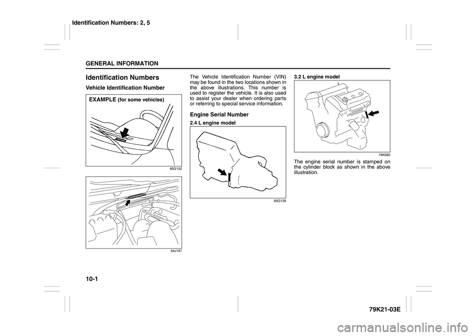
Identification NumbersVehicle Identification Number
60G152
64J197
The Vehicle Identification Number (VIN)
may be found in the two locations shown in
the above illustrations. This number is
used to register the vehicle. It is also used
to assist your dealer when ordering parts
or referring to special service information.Engine Serial Number2.4 L engine model
60G128
3.2 L engine model
79K060
The engine serial number is stamped on
the cylinder block as shown in the above
illustration.
EXAMPLE
(for some vehicles)
Identification Numbers: 2, 5
Page 320 of 337
10-3GENERAL INFORMATION
79K21-03E
On-Board Vehicle Computers
and Event Data RecordersYour vehicle is equipped with on-board
computer systems which monitor and
control several aspects of vehicle per-
formance, including the following:
Emission-related components and
engine parameters such as engine
speed and throttle position are moni-
tored to provide emissions control
and to provide optimum fuel econ-
omy. Your vehicle also has an on-
board diagnostic system which mon-
itors and records information about
emission-related malfunctions.
Signals from various sensors are
monitored to provide air bag deploy-
ment.
If your vehicle is equipped with
antilock brakes, conditions such as
vehicle speed and brake perfor-
mance are monitored, so that the
ABS system can provide effective
antilock braking. If your vehicle has
an Electronic Stability Program
(ESP
®) system, conditions such as
yaw rate, lateral acceleration, and
brake fluid pressure are monitored,
so that the ESP
® system can help
the driver control the vehicle in diffi-
cult driving situations.
Some information may be stored by
the on-board computers during normaloperation of the vehicle. This stored
information can assist technicians in
repairing the vehicle when malfunc-
tions occur. Other information is stored
only in the event of crash, by computer
systems that are commonly called
Event Data Recorders (EDRs).
In a crash event, EDRs such as the
Airbag Sensing and Diagnostic Mod-
ule (SDM) in your vehicle may record
information about the condition of the
vehicle and how it was operated, such
as data related to airbag readiness,
airbag performance, safety belt usage,
and the severity of the collision. These
data can help provide a better under-
standing of the circumstances in which
crashes and injuries occur and lead to
the designing of safer vehicles. The
SDM in your vehicle does not collect
or store personal information.
To read the stored information, special
equipment is needed and access to
the vehicle or storage device is
required. SUZUKI will not access infor-
mation about a crash event or share it
with others other than with the consent
of the vehicle owner or lessee, in
response to an official request from
the police or similar government office,
as part of SUZUKI’s defense of litiga-
tion through the discovery process, or
as required by law.In addition, once SUZUKI collects or
receives data, SUZUKI may use the
data for research conducted by
SUZUKI, make the data available for
outside research if need is shown and
confidentiality is assured, or make
summary data which does not identify
specific vehicles available for outside
research.
Others, such as law enforcement per-
sonnel, may have access to the spe-
cial equipment that can read the
information if they have access to the
vehicle or storage device.
Reporting Safety Defects: NO
Page 323 of 337
11-1
FUSES AND PROTECTED CIRCUITS
79K21-03E
11
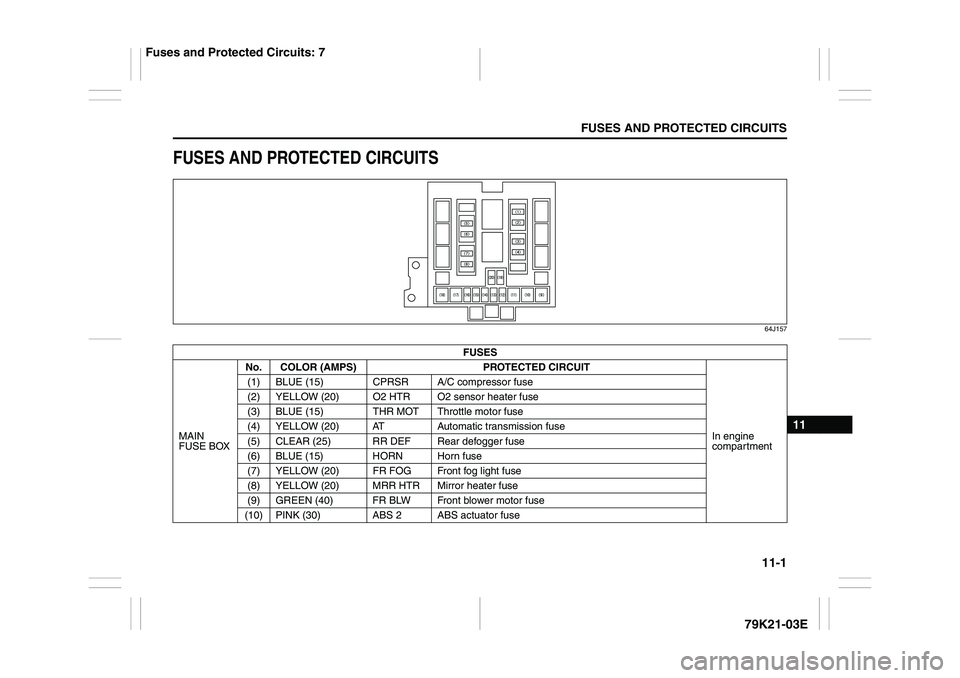
FUSES AND PROTECTED CIRCUITS
64J157
FUSES
MAIN
FUSE BOXNo. COLOR (AMPS) PROTECTED CIRCUIT
In engine
compartment (1) BLUE (15) CPRSR A/C compressor fuse
(2) YELLOW (20) O2 HTR O2 sensor heater fuse
(3) BLUE (15) THR MOT Throttle motor fuse
(4) YELLOW (20) AT Automatic transmission fuse
(5) CLEAR (25) RR DEF Rear defogger fuse
(6) BLUE (15) HORN Horn fuse
(7) YELLOW (20) FR FOG Front fog light fuse
(8) YELLOW (20) MRR HTR Mirror heater fuse
(9) GREEN (40) FR BLW Front blower motor fuse
(10) PINK (30) ABS 2ABS actuator fuse
Fuses and Protected Circuits: 7
Page 324 of 337
11-2FUSES AND PROTECTED CIRCUITS
79K21-03E
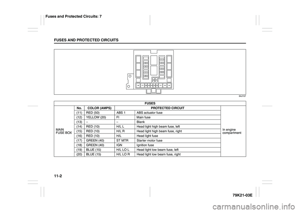
64J157
FUSES
MAIN
FUSE BOXNo. COLOR (AMPS) PROTECTED CIRCUIT
In engine
compartment (11) RED (50) ABS 1 ABS actuator fuse
(12) YELLOW (20) FI Main fuse
(13) – – Blank
(14) RED (10) H/L L Head light high beam fuse, left
(15) RED (10) H/L R Head light high beam fuse, right
(16) RED (10) H/L Head light fuse
(17) GREEN (40) ST MTR Starter motor fuse
(18) GREEN (40) IGN Ignition fuse
(19) BLUE (15) H/L LO L Head light low beam fuse, left
(20) BLUE (15) H/L LO R Head light low beam fuse, right
Fuses and Protected Circuits: 7