radio SUZUKI GRAND VITARA 2011 Owner's Manual
[x] Cancel search | Manufacturer: SUZUKI, Model Year: 2011, Model line: GRAND VITARA, Model: SUZUKI GRAND VITARA 2011Pages: 337, PDF Size: 6.21 MB
Page 209 of 337
5-56
OTHER CONTROLS AND EQUIPMENT
79K21-03E
TRACK REPEAT
The indication “TRACK RPT” appears in
the display for 2 seconds and then the
repeat indicator (E) lights.
The track being currently played is
played repeatedly.
DISC REPEAT
The indication “DISC RPT” appears in
the display for 2 seconds and then the
repeat indicator (E) lights.
When all the tracks on a disc being cur-
rently played finish playing, play starts
again at the beginning of the disc.
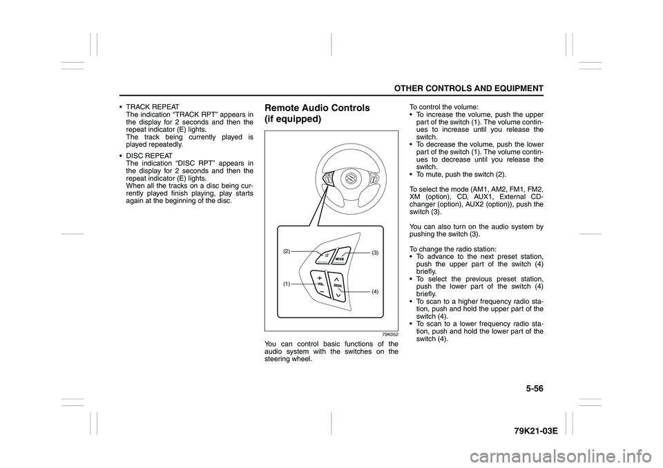
Remote Audio Controls
(if equipped)
79K052
You can control basic functions of the
audio system with the switches on the
steering wheel.To control the volume:
To increase the volume, push the upper
part of the switch (1). The volume contin-
ues to increase until you release the
switch.
To decrease the volume, push the lower
part of the switch (1). The volume contin-
ues to decrease until you release the
switch.
To mute, push the switch (2).
To select the mode (AM1, AM2, FM1, FM2,
XM (option), CD, AUX1, External CD-
changer (option), AUX2 (option)), push the
switch (3).
You can also turn on the audio system by
pushing the switch (3).
To change the radio station:
To advance to the next preset station,
push the upper part of the switch (4)
briefly.
To select the previous preset station,
push the lower part of the switch (4)
briefly.
To scan to a higher frequency radio sta-
tion, push and hold the upper part of the
switch (4).
To scan to a lower frequency radio sta-
tion, push and hold the lower part of the
switch (4).
(1)(2)
(4)(3)
Page 213 of 337
5-60
OTHER CONTROLS AND EQUIPMENT
79K21-03E
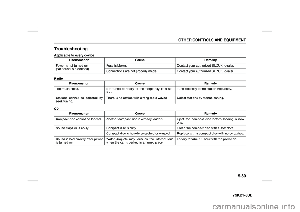
TroubleshootingApplicable to every device
Radio
CDPhenomenon Cause Remedy
Power is not turned on.
(No sound is produced)Fuse is blown. Contact your authorized SUZUKI dealer.
Connections are not properly made. Contact your authorized SUZUKI dealer.
Phenomenon Cause Remedy
Too much noise. Not tuned correctly to the frequency of a sta-
tion.Tune correctly to the station frequency.
Stations cannot be selected by
seek tuning.There is no station with strong radio waves. Select stations by manual tuning.
Phenomenon Cause Remedy
Compact disc cannot be loaded. Another compact disc is already loaded. Eject the compact disc before loading a new
one.
Sound skips or is noisy. Compact disc is dirty. Clean the compact disc with a soft cloth.
Compact disc is heavily scratched or warped. Replace with a compact disc with no scratches.
Sound is bad directly after power
is turned on.Water droplets may form on the internal lens
when the car is parked in a humid place.Let dry for about 1 hour with the power on.
Page 233 of 337
5-80
OTHER CONTROLS AND EQUIPMENT
79K21-03E
HomeLink
® (if equipped)
66J092
HomeLink
® and the HomeLink
® house are
registered trademarks of Johnson
Controls, Inc.
The HomeLink
® Wireless Control System
provides a convenient way to replace up to
three hand-held radio-frequency (RF)
transmitters used to activate devices such
as gate operators, garage door openers,
entry door locks, security systems, even
home lighting. Additional HomeLink
® infor-
mation can be found on the Internet at
www.homelink.com
or by calling 1-800-
355-3515.
Before programming HomeLink
® to a
garage door opener or gate operator, make
sure that people and objects are out of the
way of the device to prevent potential harm
or damage. When programming a garage
door opener, it is advised to park outside of
the garage. Do not use HomeLink® with
any garage door opener that lacks safety
stop and reverse features as required by
U.S. federal safety standards (this includesany garage door opener model manufac-
tured before April 1, 1982). A garage door
that cannot detect an object – signaling the
door to stop and reverse – does not meet
current U.S. federal safety standards. For
more information, contact HomeLink
® at
www.homelink.com
or by calling 1-800-
355-3515.
Retain the original transmitter of the RF
device you are programming for use in
other vehicles as well as for future
HomeLink
® programming. It is also sug-
gested that upon the sale of the vehicle,
the programmed HomeLink
® buttons be
erased for security purposes. Refer to
“Programming HomeLink
®” (step 1) only)
or, for assistance, contact HomeLink
® at
www.homelink.com
or by calling 1-800-
355-3515.
Programming HomeLink
®
NOTE:
Some vehicles may require the ignition
switch to be turned to the second (or
“accessories”) position or the “on” position
for programming and/or operation of
HomeLink
®. It is also recommended that a
new battery be placed in the hand-held
transmitter of the device being pro-
grammed to HomeLink
® for quicker train-
ing and accurate transmission of the radio-
frequency signal. Do not repeat “Program-
ming HomeLink
®” – step 1) to train addi-
tional devices to a second or thirdHomeLink
® button. Begin with “Program-
ming HomeLink
®” – step 2).
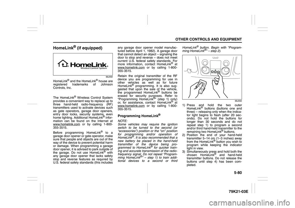
66J050
1) Press and hold the two outer
HomeLink
® buttons (buttons one and
three) – releasing only when the indica-
tor light begins to flash (after 20 sec-
onds). Do not hold the buttons for
longer than 30 seconds and do not
repeat step 1) to program a second
and/or third hand-held transmitter to the
remaining two HomeLink
® buttons.
2) Position the end of your hand-held
transmitter 5–14 cm (1–3 inches) away
from the HomeLink
® button you wish to
program while keeping the indicator
light in view.
3) Simultaneously press and hold both the
chosen HomeLink® and hand-held
transmitter buttons. Do not release the
buttons until step 4) has been com-
pleted.
Page 235 of 337
5-82
OTHER CONTROLS AND EQUIPMENT
79K21-03E
Gate Operator / Canadian Program-
mingCanadian radio-frequency laws require
transmitter signals to “time-out” (or quit)
after several seconds of transmission –
which may not be long enough for
HomeLink
® to pick up the signal during
programming. Similar to this Canadian law,
some U.S. gate operators are designed to
“time-out” in the same manner.
If you live in Canada or you are having diffi-
culties programming a gate operator by
using the Programming procedures
(regardless of where you live), replace
“Programming HomeLink
®” step 3) with
the following:
NOTE:
If programming a garage door opener or
gate operator, it is advised to unplug the
device during the “cycling” process to pre-
vent possible overheating.
3) Continue to press and hold the
HomeLink
® button while you press and
release – every two seconds (“cycle”)
your hand-held transmitter until the fre-
quency signal has successfully been
accepted by HomeLink
®. (The indicator
light will flash slowly and then rapidly.)
Proceed with “Programming HomeLink
®”
step 4) to complete.
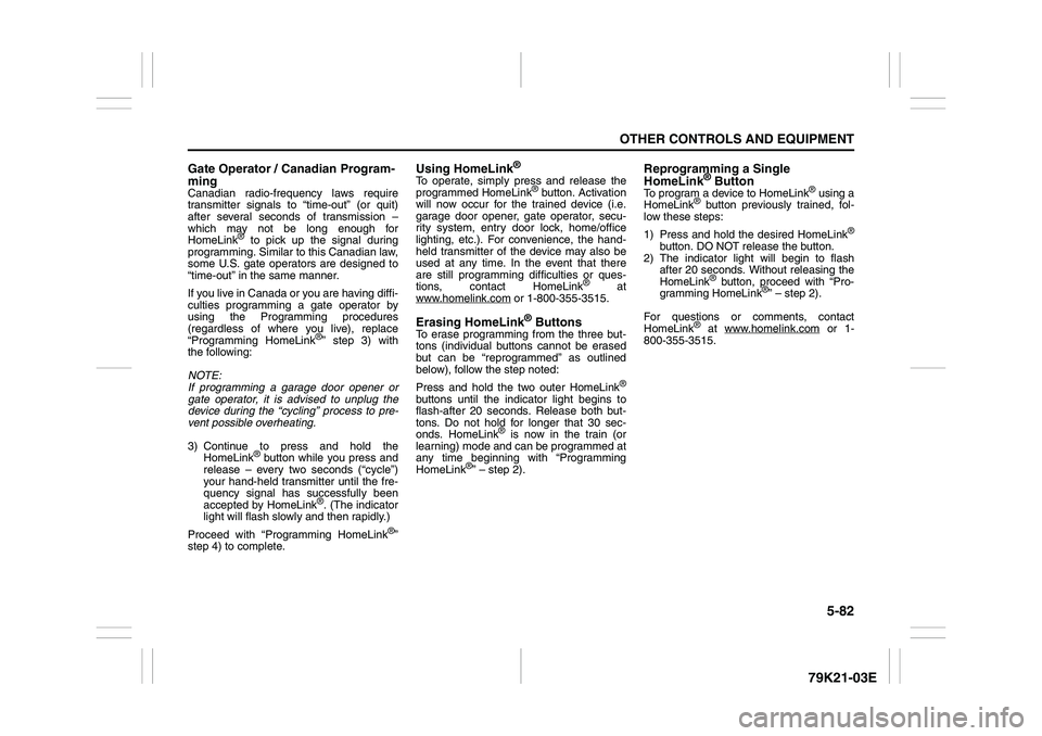
Using HomeLink
®
To operate, simply press and release the
programmed HomeLink
® button. Activation
will now occur for the trained device (i.e.
garage door opener, gate operator, secu-
rity system, entry door lock, home/office
lighting, etc.). For convenience, the hand-
held transmitter of the device may also be
used at any time. In the event that there
are still programming difficulties or ques-
tions, contact HomeLink
® at
www.homelink.com
or 1-800-355-3515.
Erasing HomeLink
® Buttons
To erase programming from the three but-
tons (individual buttons cannot be erased
but can be “reprogrammed” as outlined
below), follow the step noted:
Press and hold the two outer HomeLink
®
buttons until the indicator light begins to
flash-after 20 seconds. Release both but-
tons. Do not hold for longer that 30 sec-
onds. HomeLink
® is now in the train (or
learning) mode and can be programmed at
any time beginning with “Programming
HomeLink
®” – step 2).
Reprogramming a Single
HomeLink
® Button
To program a device to HomeLink
® using a
HomeLink
® button previously trained, fol-
low these steps:
1) Press and hold the desired HomeLink
®
button. DO NOT release the button.
2) The indicator light will begin to flash
after 20 seconds. Without releasing the
HomeLink
® button, proceed with “Pro-
gramming HomeLink
®” – step 2).
For questions or comments, contact
HomeLink
® at www.homelink.com
or 1-
800-355-3515.
Page 281 of 337
7-32
INSPECTION AND MAINTENANCE
79K21-03E Snow Tires
Your vehicle is equipped with all-sea-
son tires which are designed for use in
summer and most winter conditions.
For improved traction in severe winter
conditions, SUZUKI recommends
mounting radial snow tires on all four
wheels. Snow tires must be the same
size as the standard tires. Also be sure
to use the tires of the same type and
brand on all four wheels of your vehi-
cle.
GLOSSARY OF TIRE TERMI-
NOLOGYAccessory Weight – the combined
weight (in excess of those standard
items which may be replaced) of auto-
matic transmission, power steering,
power brakes, power windows, power
seats, radio, and heater, to the extent
that these items are available as fac-
tory-installed equipment (whether
installed or not).
Cold Tire Inflation Pressure – the pres-
sure in a tire that has been driven less
than 1 mile or has been standing for
three hours or more.
Curb Weight – the weight of a motor
vehicle with standard equipment
including the maximum capacity of
fuel, oil, and coolant, and, if so
equipped, air conditioning and addi-
tional weight optional engine.
Intended Outboard Sidewall – (1) the
sidewall that contains a whitewall,
bears white lettering or bears manu-
facturer, brand, and/or model name
molding that is higher or deeper than
the same molding on the other side-
wall of the tire, or (2) the outward fac-
ing sidewall of an asymmetrical tire
that has a particular side that mustalways face outward when mounted
on a vehicle.
Maximum Inflation Pressure – the
maximum cold inflation pressure a tire
is designed to support in normal ser-
vice.
Maximum Loaded Vehicle Weight –
the sum of curb weight, accessory
weight, vehicle capacity weight (total
load capacity), and production options
weight.
Normal Occupant Weight – 68 kilo-
grams times the number of occupants
specified in the second column of
Table 1 (shown below).
Occupant distribution – distribution of
occupants in a vehicle as specified in
the third column of Table 1 (shown
below).
Production Options Weight – the com-
bined weight of those installed regular
production options weighing over 2.3
kilograms in excess of those standard
items which they replace, not previ-
ously considered in curb weight or
accessory weight, including heavy
duty brakes, ride levelers, roof rack,
heavy duty battery, and special trim.
WARNING
(Continued) Do not use tire chains on the
spare tire. If you must use tire
chains, rearrange the wheels so
standard tires and wheels are
fitted to the rear axle.
Replace the spare tire with a
new one as soon as the tread
wear indicator appears.
When replacing the spare tire,
use a replacement tire with the
exact same size and construc-
tion.
Battery: 9
Fuses: 7
Page 287 of 337
7-38
INSPECTION AND MAINTENANCE
79K21-03E
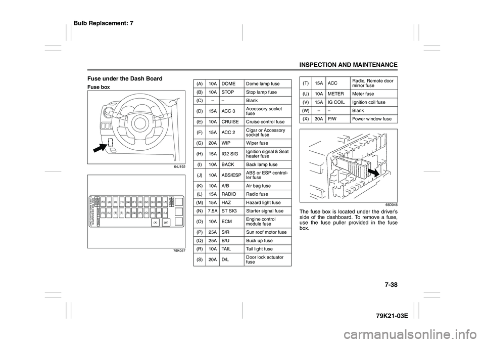
Fuse under the Dash BoardFuse box
64J192
79K05765D045
The fuse box is located under the driver’s
side of the dashboard. To remove a fuse,
use the fuse puller provided in the fuse
box.
SPARESPARE
SPARE
SPARE
USE THE DESIGNATED
FUSES AND RELAYS ONLYSPARE SPARE
(A)
(B)
(C)
(D)
(E)
(F)
(G)
(H)(I)
(J)
(L)
(M)
(N)
(O)
(P)
(Q)
(R)
(S)
(T)
(U)
(V)(K)
(W)
(X)
(A) 10A DOME Dome lamp fuse
(B) 10A STOP Stop lamp fuse
(C) – – Blank
(D) 15A ACC 3Accessory socket
fuse
(E) 10A CRUISE Cruise control fuse
(F) 15A ACC 2Cigar or Accessory
socket fuse
(G) 20A WIP Wiper fuse
(H) 15A IG2 SIGIgnition signal & Seat
heater fuse
(I) 10A BACK Back lamp fuse
(J) 10A ABS/ESPABS or ESP control-
ler fuse
(K) 10A A/B Air bag fuse
(L) 15A RADIO Radio fuse
(M) 15A HAZ Hazard light fuse
(N) 7.5A ST SIG Starter signal fuse
(O) 10A ECMEngine control
module fuse
(P) 25A S/R Sun roof motor fuse
(Q) 25A B/U Buck up fuse
(R) 10A TAIL Tail light fuse
(S) 20A D/LDoor lock actuator
fuse
(T) 15A ACCRadio, Remote door
mirror fuse
(U) 10A METER Meter fuse
(V) 15A IG COIL Ignition coil fuse
(W) – – Blank
(X) 30A P/W Power window fuse
Bulb Replacement: 7
Page 325 of 337
11-3
FUSES AND PROTECTED CIRCUITS
79K21-03E
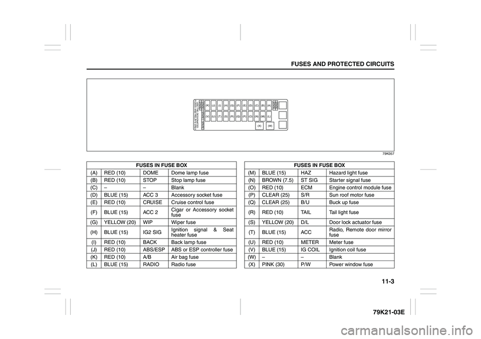
79K057
FUSES IN FUSE BOX FUSES IN FUSE BOX
(A) RED (10) DOME Dome lamp fuse (M) BLUE (15) HAZ Hazard light fuse
(B) RED (10) STOP Stop lamp fuse (N) BROWN (7.5) ST SIG Starter signal fuse
(C) – – Blank (O) RED (10) ECM Engine control module fuse
(D) BLUE (15) ACC 3 Accessory socket fuse(P) CLEAR (25) S/R Sun roof motor fuse
(E) RED (10) CRUISE Cruise control fuse (Q) CLEAR (25) B/U Buck up fuse
(F) BLUE (15) ACC 2Cigar or Accessory socket
fuse(R) RED (10) TAIL Tail light fuse
(G) YELLOW (20) WIP Wiper fuse (S) YELLOW (20) D/L Door lock actuator fuse
(H) BLUE (15) IG2 SIGIgnition signal & Seat
heater fuse(T) BLUE (15) ACCRadio, Remote door mirror
fuse
(I) RED (10) BACK Back lamp fuse (U) RED (10) METER Meter fuse
(J) RED (10) ABS/ESP ABS or ESP controller fuse (V) BLUE (15) IG COIL Ignition coil fuse
(K) RED (10) A/B Air bag fuse (W) – – Blank
(L) BLUE (15) RADIO Radio fuse (X) PINK (30) P/W Power window fuse
SPARESPARE
SPARE
SPARE
USE THE DESIGNATED
FUSES AND RELAYS ONLYSPARE SPARE
(A)
(B)
(C)
(D)
(E)
(F)
(G)
(H)(I)
(J)
(L)
(M)
(N)
(O)
(P)
(Q)
(R)
(S)
(T)
(U)
(V)(K)
(W)
(X)
Page 333 of 337
13-3
INDEX79K21-03E
If the Engine Overheats
......................................................8-9
If the Starter Does Not Operate
..........................................8-8
If You Cannot Shift Automatic Transmission Gearshift
Lever Out of “P” (PARK)
.....................................................3-15
If Your Vehicle Gets Stuck ..................................................4-6
Ignition Key Reminder
........................................................2-1
Ignition Switch
.....................................................................3-3
Illumination Indicator Light
................................................2-64
Important Vehicle Design Features To Know
...................4-1
Improving Fuel Economy
....................................................4-3
Information Display
.............................................................2-67
Inside Rearview Mirror ........................................................2-17
Installation with Lap-Shoulder Seat Belts
(Child Restraint with No Top Strap)
...................................2-35
Installation with the LATCH System ..................................2-38
Installation-Child Restraint with Top Strap
.......................2-40
Instrument Cluster
...............................................................2-54
Interior Light Switch ............................................................5-64
JJacking Instructions
............................................................8-2
Jump Starting Instructions
.................................................8-7
KKeyless Entry System Transmitter (Type B)
.....................2-11
Keyless Start System Indicator Light
................................2-63
Keyless Start System Remote Controller (Type A)
..........2-5
Keyless Start System Remote Controller/
Keyless Entry System Transmitter
....................................2-4
Keys
......................................................................................2-1
LLap-Shoulder Belt
................................................................2-28
Lighting Control Lever
........................................................2-75Lighting Operation
.............................................................. 2-76
Lights “On” reminder ......................................................... 2-78
Listening to a CD
.......................................................5-15
, 5-42
Listening to a CD from an External CD Changer
(Option)
.......................................................................5-28
, 5-54
Listening to a XM Satellite Radio (Option)
..............5-25
, 5-51
Listening to Audio for AUX (Option)
.............. 5-27
, 5-49
, 5-53
Listening to the Radio
...............................................5-13
, 5-40
Low Fuel Warning Light
..................................................... 2-62
Low Tire Pressure Warning Light
.............................2-55
, 3-38
Luggage Compartment Cover
........................................... 5-74
Luggage Compartment Light ............................................. 5-65
Luggage Restraint Loops
................................................... 5-78
MMaintenance Recommended under Severe Driving
Conditions
........................................................................... 7-7
Maintenance Schedule
....................................................... 7-2
Malfunction Indicator Light
................................................ 2-61
Manual Transmission
......................................................... 3-11
Master Warning Indicator Light
......................................... 2-64
Mirrors
.................................................................................. 2-17
NNational Highway Traffic Safety Administration
(NHTSA)
............................................................................... 10-4
OOdometer
............................................................................. 2-70
Off-Road Driving
................................................................. 4-6
Oil Level Check ................................................................... 7-10
Oil Pressure Light ............................................................... 2-60
On-Board Vehicle Computers and Event Data
Recorders
............................................................................ 10-3
Page 334 of 337
13-4INDEX
79K21-03E
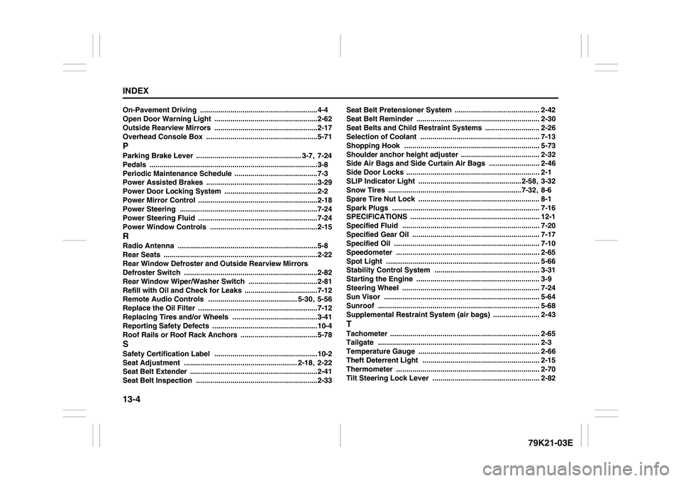
On-Pavement Driving
..........................................................4-4
Open Door Warning Light
...................................................2-62
Outside Rearview Mirrors ...................................................2-17
Overhead Console Box
.......................................................5-71
PParking Brake Lever
.................................................... 3-7
, 7-24
Pedals
...................................................................................3-8
Periodic Maintenance Schedule
.........................................7-3
Power Assisted Brakes
.......................................................3-29
Power Door Locking System
..............................................2-2
Power Mirror Control
...........................................................2-18
Power Steering
....................................................................7-24
Power Steering Fluid
...........................................................7-24
Power Window Controls
.....................................................2-15
RRadio Antenna
.....................................................................5-8
Rear Seats
............................................................................2-22
Rear Window Defroster and Outside Rearview Mirrors
Defroster Switch
..................................................................2-82
Rear Window Wiper/Washer Switch
..................................2-81
Refill with Oil and Check for Leaks ....................................7-12
Remote Audio Controls
............................................ 5-30
, 5-56
Replace the Oil Filter
...........................................................7-12
Replacing Tires and/or Wheels
..........................................3-41
Reporting Safety Defects
....................................................10-4
Roof Rails or Roof Rack Anchors
......................................5-78
SSafety Certification Label
...................................................10-2
Seat Adjustment
........................................................ 2-18
, 2-22
Seat Belt Extender
...............................................................2-41
Seat Belt Inspection ............................................................2-33Seat Belt Pretensioner System
.......................................... 2-42
Seat Belt Reminder
............................................................. 2-30
Seat Belts and Child Restraint Systems
........................... 2-26
Selection of Coolant
........................................................... 7-13
Shopping Hook
................................................................... 5-73
Shoulder anchor height adjuster
....................................... 2-32
Side Air Bags and Side Curtain Air Bags
......................... 2-46
Side Door Locks
.................................................................. 2-1
SLIP Indicator Light
...................................................2-58
, 3-32
Snow Tires
..................................................................7-32
, 8-6
Spare Tire Nut Lock
............................................................ 8-1
Spark Plugs
......................................................................... 7-16
SPECIFICATIONS
................................................................ 12-1
Specified Fluid
.................................................................... 7-20
Specified Gear Oil ............................................................... 7-17
Specified Oil
........................................................................ 7-10
Speedometer ....................................................................... 2-65
Spot Light
............................................................................ 5-66
Stability Control System
.................................................... 3-31
Starting the Engine
............................................................. 3-9
Steering Wheel
.................................................................... 7-24
Sun Visor
............................................................................. 5-64
Sunroof
................................................................................ 5-68
Supplemental Restraint System (air bags)
....................... 2-43
TTachometer
.......................................................................... 2-65
Tailgate
................................................................................ 2-3
Temperature Gauge
............................................................ 2-66
Theft Deterrent Light .......................................................... 2-15
Thermometer
....................................................................... 2-70
Tilt Steering Lock Lever
..................................................... 2-82