4 wheel drive SUZUKI GRAND VITARA 2018 Owner's Manual
[x] Cancel search | Manufacturer: SUZUKI, Model Year: 2018, Model line: GRAND VITARA, Model: SUZUKI GRAND VITARA 2018Pages: 482, PDF Size: 21 MB
Page 279 of 482
5-37
OTHER CONTROLS AND EQUIPMENT
54P00-01E
You can use the air conditioning switch (6)
to manually turn the air conditioner on or off
according to your preference. When you
turn the air conditioning switch off, the cli-
mate control system cannot lower the inside
temperature below outside temperature.
To turn the climate control system off, push
“OFF” switch (7).
NOTE:
If “AUTO” on the display blinks, there is a
problem in the heating system and/or air
conditioning system. You should have the
system inspected by an authorized
SUZUKI dealer.
NOTE:
• To find the temperature at which you are
most comfortable, start with the 22°C
(72°F) or 25°C (75°F) setting. (the tem-
perature vary depending on vehicle
specifications.).
• If you turn the temperature selector (1)
until “HI” or “LO” appears on the display,
the climate control system will operate at
maximum heating or cooling and the
blower will run at full speed.
• To avoid blowing cold air in cold weather
or hot air in hot weather, the system will
delay turning on the blower until warmed
or chilled air is available.
• If your vehicle has been left in the sun
with the windows closed, it will cool
faster if you open the windows briefly.
• Even under the automatic operation, you
can set individual selectors to the manualmode. The manually selected functions
are maintained, and the other functions
remain under automatic operation.
• If the windshield and/or the front door
windows are fogged, push the defrost
switch (5) to turn on the defroster, or
push the air flow selector (4) to change
the air flow to HEAT & DEFROST posi-
tion to defog the windows.
• To return the blower speed selector (2),
air intake selector (3), and air flow selec-
tor (4) to automatic operation, push
“AUTO” switch (8).
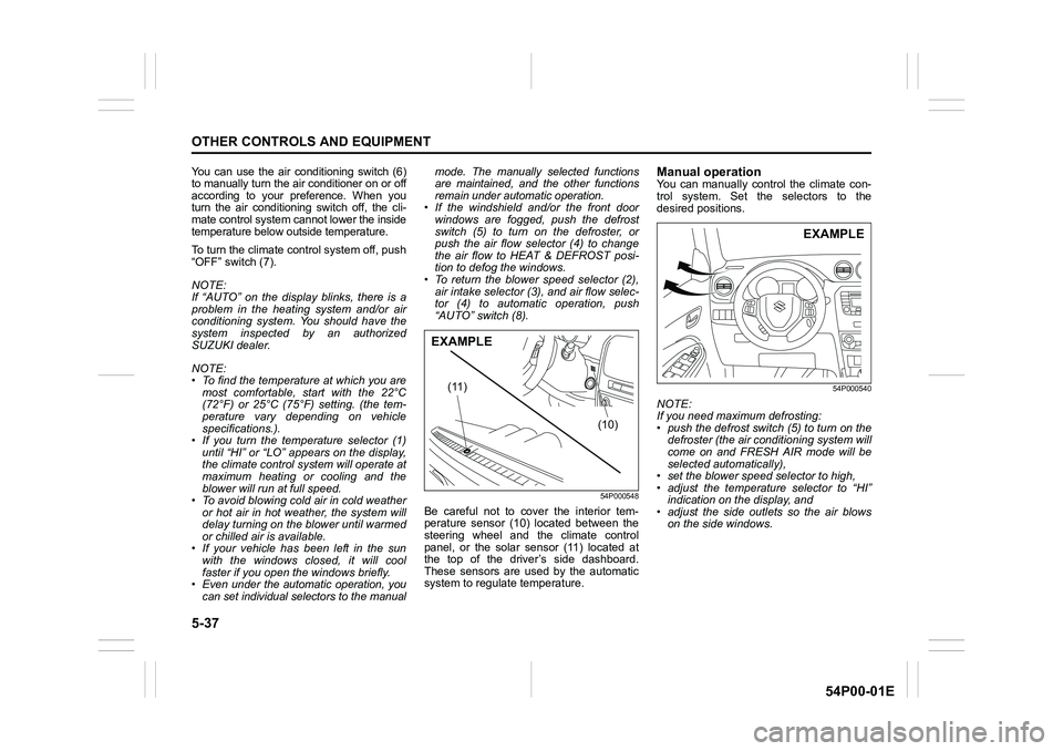
54P000548
Be careful not to cover the interior tem-
perature sensor (10) located between the
steering wheel and the climate control
panel, or the solar sensor (11) located at
the top of the driver’s side dashboard.
These sensors are used by the automatic
system to regulate temperature.
Manual operationYou can manually control the climate con-
trol system. Set the selectors to the
desired positions.
54P000540
NOTE:
If you need maximum defrosting:
• push the defrost switch (5) to turn on the
defroster (the air conditioning system will
come on and FRESH AIR mode will be
selected automatically),
• set the blower speed selector to high,
• adjust the temperature selector to “HI”
indication on the display, and
• adjust the side outlets so the air blows
on the side windows.
(10) (11)
EXAMPLE
EXAMPLE
Page 336 of 482
6-4
VEHICLE LOADING AND TOWING
54P00-01E
WA R N I N G
Your vehicle should be handled in a
different way when towing a trailer.
For the safety of yourself and others,
observe the following precautions:
• Practice turning, stopping, and
reversing before you begin towing
a trailer in traffic. Do not tow a
trailer in traffic until you are confi-
dent that you can handle the vehi-
cle and trailer safely.
• Never exceed towing speed limits
or 80 km/h (50 mph), whichever is
lower.
• Never drive at a speed that causes
shaking or swaying of the trailer. If
you notice even the slightest sign
of shaking or swaying, slow down.
• When roads are wet, slippery or
rough, drive at a slower speed than
you would on dry or smooth roads.
Failure to slow down when road
conditions are bad can result in
loss of control.
• Always have someone guide you
when reversing.
(Continued)
WA R N I N G
(Continued)
• Allow adequate stopping distance.
Stopping distance is increased
when you tow a trailer. For each 16
km/h (10 mph) of speed, allow at
least one vehicle and trailer length
between you and the vehicle
ahead. Allow a greater stopping
distance if roads are wet or slip-
pery.
• If the trailer has over-run brakes,
apply the brakes gradually to avoid
snatching caused by the trailer
wheels locking.
• Slow down before corners and
maintain a steady speed while cor-
nering. Deceleration or accelera-
tion while cornering can result in
loss of control. Remember that a
larger than normal turning radius is
needed because the trailer wheels
will be closer than vehicle wheels
to the inside of the turn.
• Avoid sudden acceleration and
stopping of the vehicle. Do not
make quick maneuvers unless they
are necessary.
• Slow down in cross winds and be
prepared for gusts of wind from
large passing vehicles.
(Continued)
WA R N I N G
(Continued)
• Be careful when overtaking other
vehicles. Allow enough room for
your trailer before changing lanes,
and use turn signal lights properly
in advance.
• Slow down and shift into a lower
gear before you reach long or steep
downhill grades. It is hazardous to
attempt downshifting while you are
descending a hill.
• Do not step on the brake pedal
strongly. This could cause the
brakes to over-heat resulting in
reduced braking efficiency. Use
engine braking as much as possi-
ble.
• Because of the added trailer
weight, your engine may overheat
on hot days when going up long or
steep hills. Pay attention to your
engine temperature gauge. If it indi-
cates overheating, pull off the road
and stop the vehicle in a safe place.
Refer to “Engine trouble: Overheat-
ing” in “EMERGENCY SERVICE”
section.
Page 354 of 482
7-16
INSPECTION AND MAINTENANCE
54P00-01E
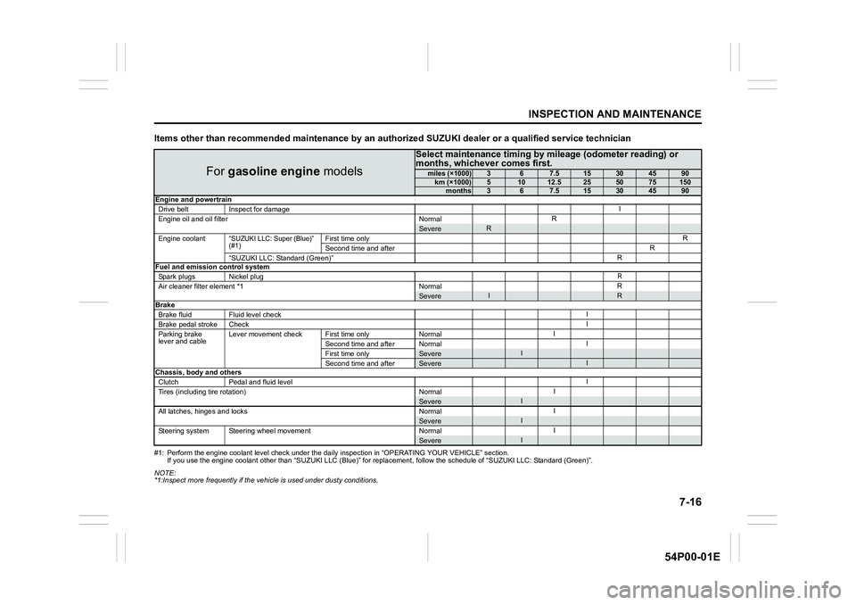
Items other than recommended maintenance by an authorized SUZUKI dealer or a qualified service technician
#1: Perform the engine coolant level check under the daily inspection in “OPERATING YOUR VEHICLE” section.
If you use the engine coolant other than “SUZUKI LLC (Blue)” for replacement, follow the schedule of “SUZUKI LLC: Standard (Green)”.
NOTE:
*1:Inspect more frequently if the vehicle is used under dusty conditions.
For gasoline engine models
Select maintenance timing by mileage (odometer reading) or
months, whichever comes first.
miles (×1000)367.515304590km (×1000)51012.5255075150months367.515304590
Engine and powertrain
Drive belt Inspect for damageI
Engine oil and oil filter NormalR
SevereR
Engine coolant“SUZUKI LLC: Super (Blue)”
(#1)First time onlyR
Second time and afterR
“SUZUKI LLC: Standard (Green)”R
Fuel and emission control system
Spark plugs Nickel plug
R
Air cleaner filter element *1 NormalRSevereIRBrake
Brake fluid Fluid level checkI
Brake pedal stroke CheckI
Parking brake
lever and cableLever movement check First time only NormalI
Second time and after NormalI
First time only
SevereI
Second time and afterSevereIChassis, body and others
Clutch Pedal and fluid levelI
Tires (including tire rotation) NormalI
SevereI
All latches, hinges and locks NormalISevereI
Steering system Steering wheel movement NormalISevereI
Page 357 of 482
7-19
INSPECTION AND MAINTENANCE
54P00-01E
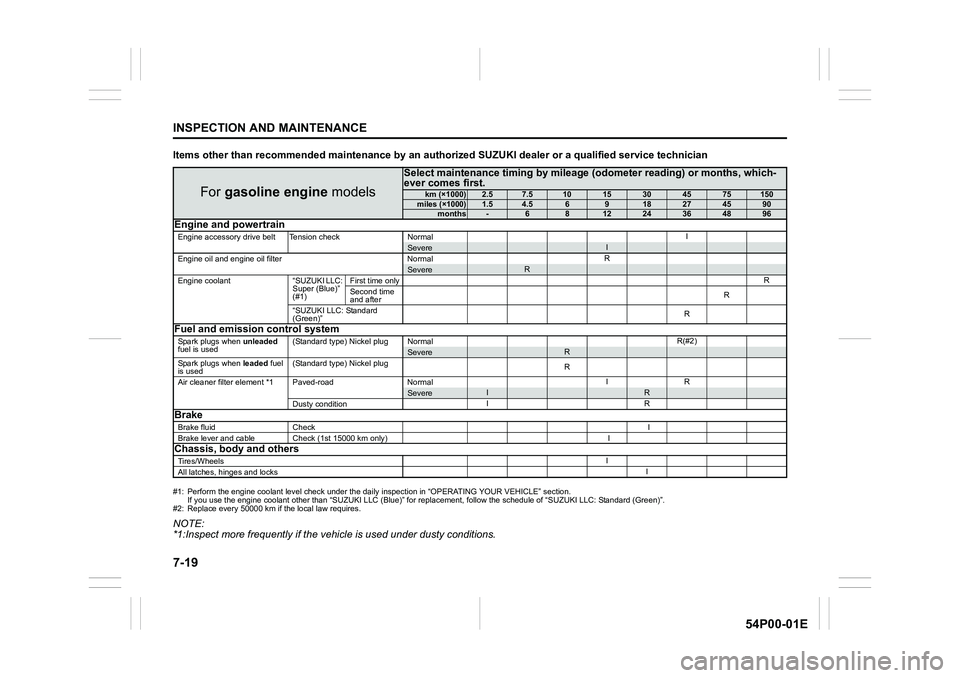
Items other than recommended maintenance by an authorized SUZUKI dealer or a qualified service technician
#1: Perform the engine coolant level check under the daily inspection in “OPERATING YOUR VEHICLE” section.
If you use the engine coolant other than “SUZUKI LLC (Blue)” for replacement, follow the schedule of “SUZUKI LLC: Standard (Green)”.
#2: Replace every 50000 km if the local law requires.
NOTE:
*1:Inspect more frequently if the vehicle is used under dusty conditions.
For gasoline engine models
Select maintenance timing by mileage (odometer reading) or months, which-
ever comes first.
km (×1000)2.57.51015304575150miles (×1000)1.54.56918274590months-681224364896Engine and powertrain
Engine accessory drive belt Tension check NormalISevereI
Engine oil and engine oil filter NormalRSevereR
Engine coolant “SUZUKI LLC:
Super (Blue)”
(#1)First time onlyR
Second time
and afterR
“SUZUKI LLC: Standard
(Green)”R
Fuel and emission control system
Spark plugs when unleaded
fuel is used(Standard type) Nickel plug NormalR(#2)SevereR
Spark plugs when leaded fuel
is used(Standard type) Nickel plug
R
Air cleaner filter element *1 Paved-road NormalIR
SevereIR
Dusty conditionIRBrake
Brake fluid CheckI
Brake lever and cable Check (1st 15000 km only) I
Chassis, body and others
Tires/WheelsI
All latches, hinges and locksI
Page 375 of 482
7-37
INSPECTION AND MAINTENANCE
54P00-01E
54G136
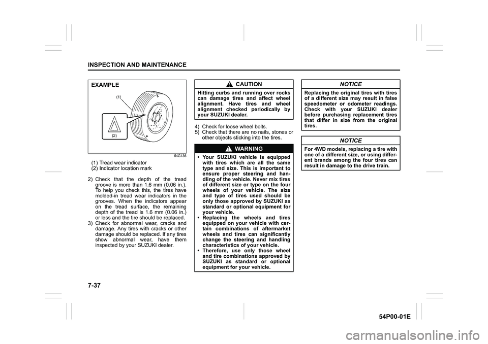
(1) Tread wear indicator
(2) Indicator location mark
2) Check that the depth of the tread
groove is more than 1.6 mm (0.06 in.).
To help you check this, the tires have
molded-in tread wear indicators in the
grooves. When the indicators appear
on the tread surface, the remaining
depth of the tread is 1.6 mm (0.06 in.)
or less and the tire should be replaced.
3) Check for abnormal wear, cracks and
damage. Any tires with cracks or other
damage should be replaced. If any tires
show abnormal wear, have them
inspected by your SUZUKI dealer.4) Check for loose wheel bolts.
5) Check that there are no nails, stones or
other objects sticking into the tires.
EXAMPLECAUTION
Hitting curbs and running over rocks
can damage tires and affect wheel
alignment. Have tires and wheel
alignment checked periodically by
your SUZUKI dealer.
WA R N I N G
• Your SUZUKI vehicle is equipped
with tires which are all the same
type and size. This is important to
ensure proper steering and han-
dling of the vehicle. Never mix tires
of different size or type on the four
wheels of your vehicle. The size
and type of tires used should be
only those approved by SUZUKI as
standard or optional equipment for
your vehicle.
• Replacing the wheels and tires
equipped on your vehicle with cer-
tain combinations of aftermarket
wheels and tires can significantly
change the steering and handling
characteristics of your vehicle.
• Therefore, use only those wheel
and tire combinations approved by
SUZUKI as standard or optional
equipment for your vehicle.
NOTICE
Replacing the original tires with tires
of a different size may result in false
speedometer or odometer readings.
Check with your SUZUKI dealer
before purchasing replacement tires
that differ in size from the original
tires.
NOTICE
For 4WD models, replacing a tire with
one of a different size, or using differ-
ent brands among the four tires can
result in damage to the drive train.
Page 385 of 482
7-47
INSPECTION AND MAINTENANCE
54P00-01E
61MM0B078
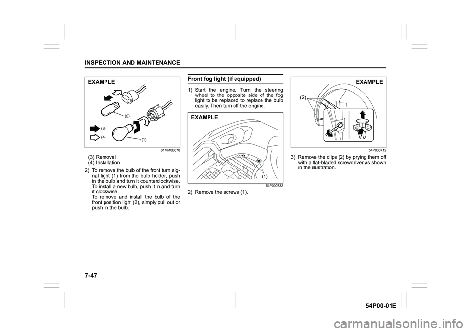
(3) Removal
(4) Installation
2) To remove the bulb of the front turn sig-
nal light (1) from the bulb holder, push
in the bulb and turn it counterclockwise.
To install a new bulb, push it in and turn
it clockwise.
To remove and install the bulb of the
front position light (2), simply pull out or
push in the bulb.
Front fog light (if equipped)
1) Start the engine. Turn the steering
wheel to the opposite side of the fog
light to be replaced to replace the bulb
easily. Then turn off the engine.
54P000732
2) Remove the screws (1).
54P000712
3) Remove the clips (2) by prying them off
with a flat-bladed screwdriver as shown
in the illustration.
(2)
(1) (3)
(4)
EXAMPLE
(1)
EXAMPLE
(2)
EXAMPLE
Page 387 of 482
7-49
INSPECTION AND MAINTENANCE
54P00-01E
1) Start the engine. Turn the steering
wheel to the opposite side of the fog
light to be replaced the bulb easily.
Then turn off the engine.
54P000732
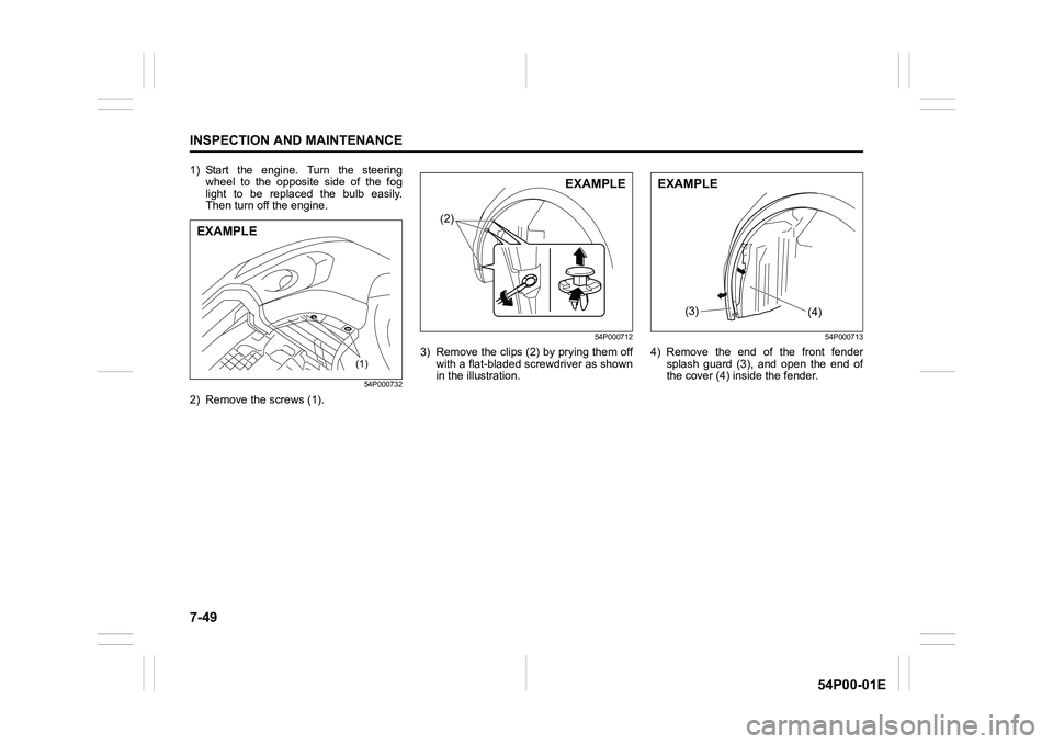
2) Remove the screws (1).
54P000712
3) Remove the clips (2) by prying them off
with a flat-bladed screwdriver as shown
in the illustration.
54P000713
4) Remove the end of the front fender
splash guard (3), and open the end of
the cover (4) inside the fender.(1)
EXAMPLE
(2)
EXAMPLE
(3)(4)
EXAMPLE
Page 407 of 482
8-7
EMERGENCY SERVICE
54P00-01E
Emergency repair
1) Place the vehicle on level, hard ground.
Set the parking brake firmly and shift
into “R” (Reverse).
Turn on the hazard warning flasher if
your vehicle is near traffic.
Block the front and rear of the wheel
diagonally opposite of the wheel being
repaired.
2) Take out the sealant bottle and the
compressor.
3) At the top of the compressor, remove
the cap that covers the socket for the
sealant bottle, and then screw the bot-
tle into the socket.
4) Unscrew the valve cap from the tire
valve.
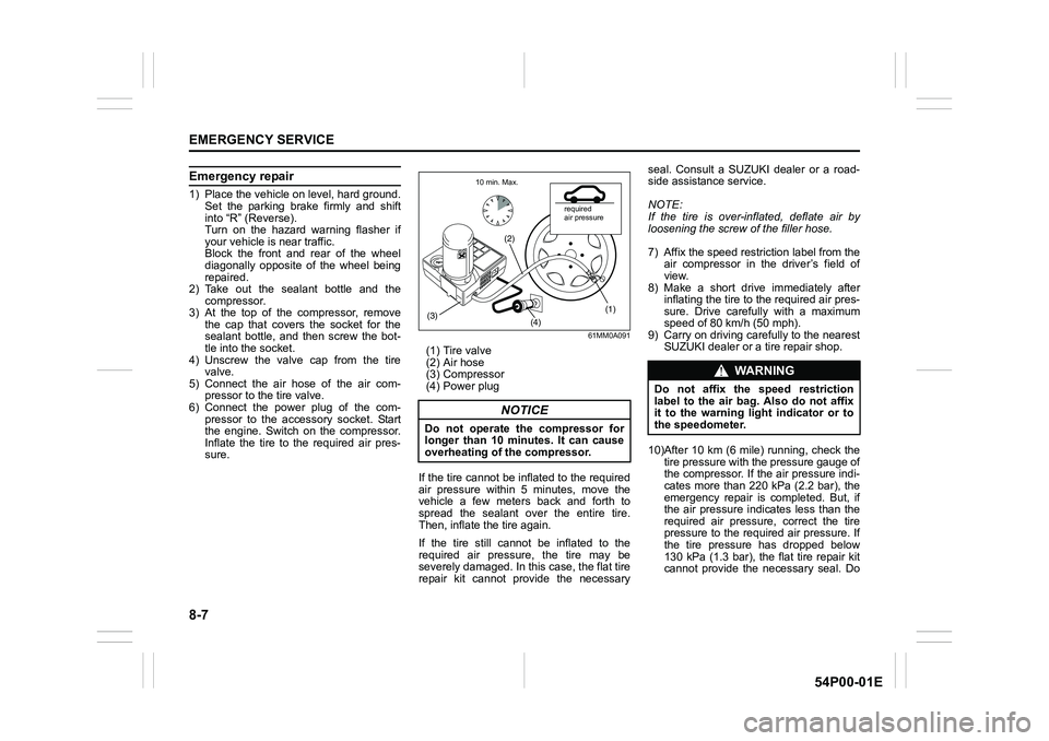
5) Connect the air hose of the air com-
pressor to the tire valve.
6) Connect the power plug of the com-
pressor to the accessory socket. Start
the engine. Switch on the compressor.
Inflate the tire to the required air pres-
sure.
61MM0A091
(1) Tire valve
(2) Air hose
(3) Compressor
(4) Power plug
If the tire cannot be inflated to the required
air pressure within 5 minutes, move the
vehicle a few meters back and forth to
spread the sealant over the entire tire.
Then, inflate the tire again.
If the tire still cannot be inflated to the
required air pressure, the tire may be
severely damaged. In this case, the flat tire
repair kit cannot provide the necessaryseal. Consult a SUZUKI dealer or a road-
side assistance service.
NOTE:
If the tire is over-inflated, deflate air by
loosening the screw of the filler hose.
7) Affix the speed restriction label from the
air compressor in the driver’s field of
view.
8) Make a short drive immediately after
inflating the tire to the required air pres-
sure. Drive carefully with a maximum
speed of 80 km/h (50 mph).
9) Carry on driving carefully to the nearest
SUZUKI dealer or a tire repair shop.
10)After 10 km (6 mile) running, check the
tire pressure with the pressure gauge of
the compressor. If the air pressure indi-
cates more than 220 kPa (2.2 bar), the
emergency repair is completed. But, if
the air pressure indicates less than the
required air pressure, correct the tire
pressure to the required air pressure. If
the tire pressure has dropped below
130 kPa (1.3 bar), the flat tire repair kit
cannot provide the necessary seal. Do
NOTICE
Do not operate the compressor for
longer than 10 minutes. It can cause
overheating of the compressor.
(1)
(4)
(2)
(3)
required
air pressure 10 min. Max.
WA R N I N G
Do not affix the speed restriction
label to the air bag. Also do not affix
it to the warning light indicator or to
the speedometer.
Page 410 of 482
8-10
EMERGENCY SERVICE
54P00-01E
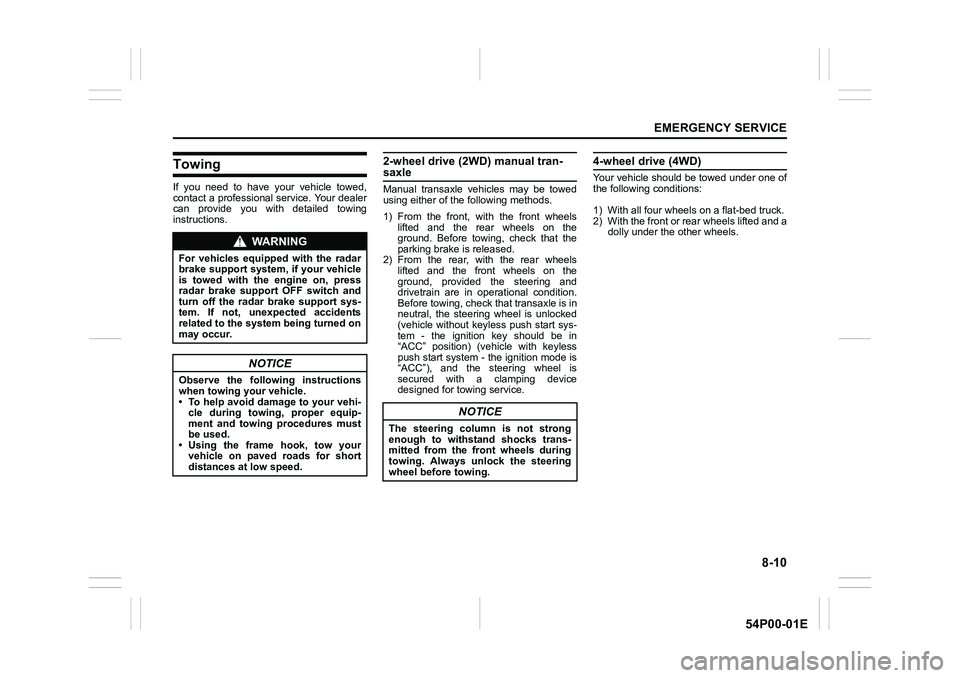
Towing
If you need to have your vehicle towed,
contact a professional service. Your dealer
can provide you with detailed towing
instructions.
2-wheel drive (2WD) manual tran-saxle
Manual transaxle vehicles may be towed
using either of the following methods.
1) From the front, with the front wheels
lifted and the rear wheels on the
ground. Before towing, check that the
parking brake is released.
2) From the rear, with the rear wheels
lifted and the front wheels on the
ground, provided the steering and
drivetrain are in operational condition.
Before towing, check that transaxle is in
neutral, the steering wheel is unlocked
(vehicle without keyless push start sys-
tem - the ignition key should be in
“ACC” position) (vehicle with keyless
push start system - the ignition mode is
“ACC”), and the steering wheel is
secured with a clamping device
designed for towing service.
4-wheel drive (4WD)
Your vehicle should be towed under one of
the following conditions:
1) With all four wheels on a flat-bed truck.
2) With the front or rear wheels lifted and a
dolly under the other wheels.
WA R N I N G
For vehicles equipped with the radar
brake support system, if your vehicle
is towed with the engine on, press
radar brake support OFF switch and
turn off the radar brake support sys-
tem. If not, unexpected accidents
related to the system being turned on
may occur.
NOTICE
Observe the following instructions
when towing your vehicle.
• To help avoid damage to your vehi-
cle during towing, proper equip-
ment and towing procedures must
be used.
• Using the frame hook, tow your
vehicle on paved roads for short
distances at low speed.
NOTICE
The steering column is not strong
enough to withstand shocks trans-
mitted from the front wheels during
towing. Always unlock the steering
wheel before towing.
Page 422 of 482
10-2
GENERAL INFORMATION
54P00-01E
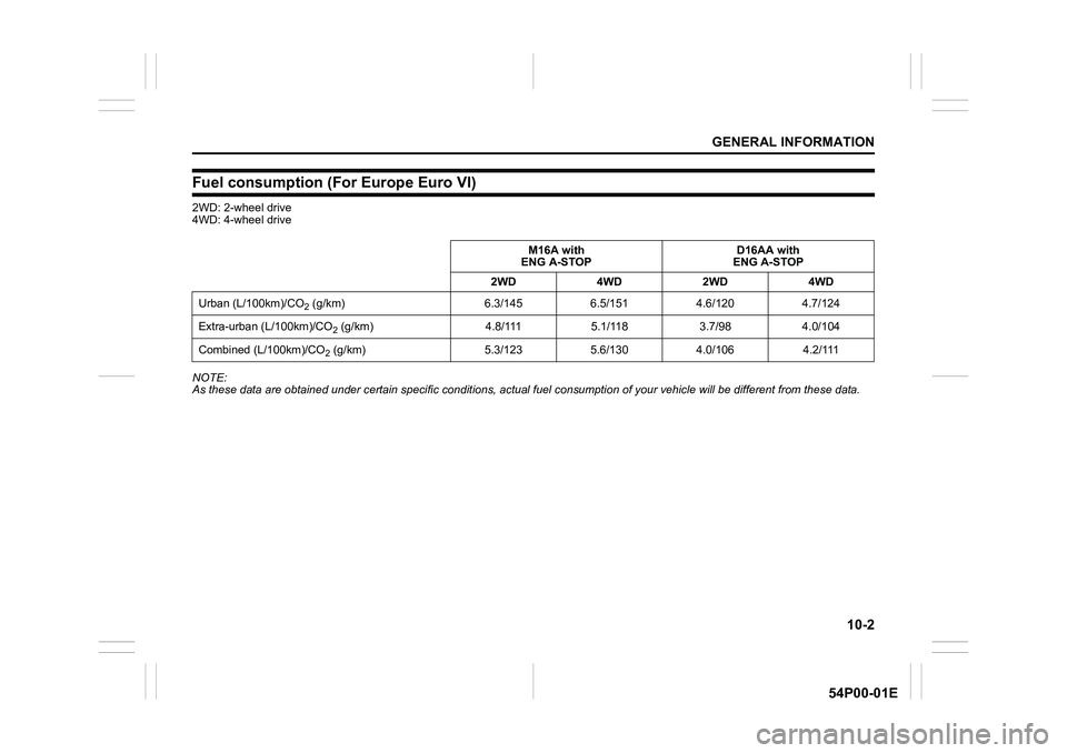
Fuel consumption (For Europe Euro VI)
2WD: 2-wheel drive
4WD: 4-wheel drive
NOTE:
As these data are obtained under certain specific conditions, actual fuel consumption of your vehicle will be different from these data. M16A with
ENG A-STOPD16AA with
ENG A-STOP
2WD4WD2WD4WD
Urban (L/100km)/CO
2 (g/km) 6.3/145 6.5/151 4.6/120 4.7/124
Extra-urban (L/100km)/CO
2 (g/km) 4.8/111 5.1/118 3.7/98 4.0/104
Combined (L/100km)/CO
2 (g/km) 5.3/123 5.6/130 4.0/106 4.2/111