SUZUKI GRAND VITARA 2022 Manual Online
Manufacturer: SUZUKI, Model Year: 2022, Model line: GRAND VITARA, Model: SUZUKI GRAND VITARA 2022Pages: 482, PDF Size: 21 MB
Page 81 of 482
2-59
BEFORE DRIVING
54P00-01E
65D610
54G582
Even though your vehicle is moderately
damaged by a crash, it may not be severe
enough to trigger front, side or side curtain
air bags to inflate. If your vehicle sustains
any front-end or side damage, have the air
bag system inspected by an authorized
SUZUKI dealer to ensure that it works
properly.
Your vehicle is equipped with a diagnostic
module which records information about
the air bag system if the air bags deploy in
a crash. The module records information
about overall system status, and which
sensors activated the deployment.
Servicing the air bag system
If the air bags inflate, have the air bags
and related components replaced by an
authorized SUZUKI dealer as soon as pos-
sible.
If your vehicle ever gets in deep water and
the driver’s floor is submerged, the air bag
controller could be damaged. If this hap-
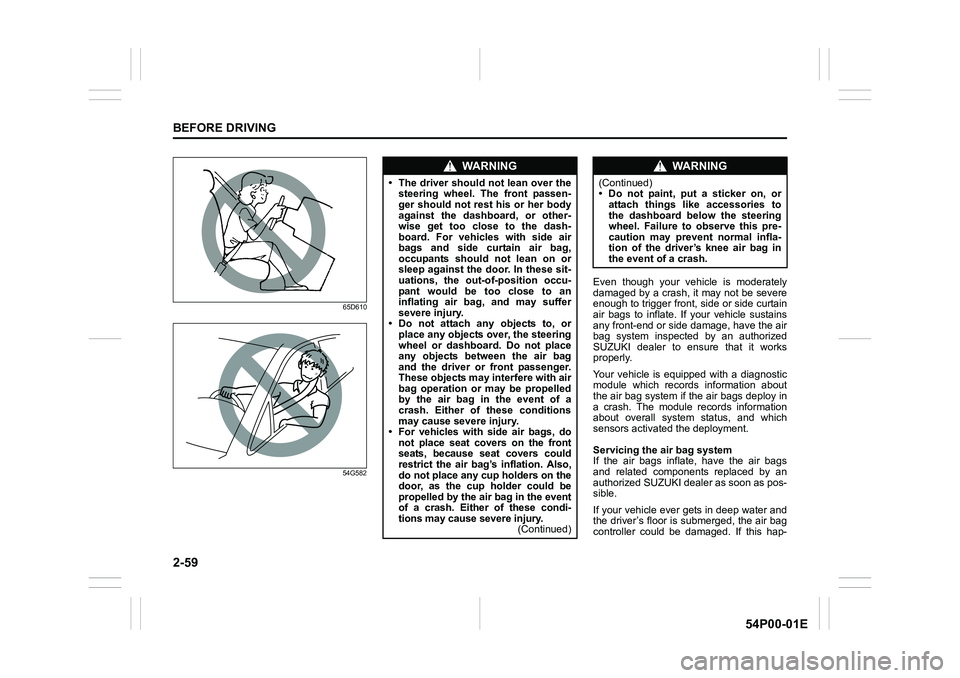
WA R N I N G
• The driver should not lean over the
steering wheel. The front passen-
ger should not rest his or her body
against the dashboard, or other-
wise get too close to the dash-
board. For vehicles with side air
bags and side curtain air bag,
occupants should not lean on or
sleep against the door. In these sit-
uations, the out-of-position occu-
pant would be too close to an
inflating air bag, and may suffer
severe injury.
• Do not attach any objects to, or
place any objects over, the steering
wheel or dashboard. Do not place
any objects between the air bag
and the driver or front passenger.
These objects may interfere with air
bag operation or may be propelled
by the air bag in the event of a
crash. Either of these conditions
may cause severe injury.
• For vehicles with side air bags, do
not place seat covers on the front
seats, because seat covers could
restrict the air bag’s inflation. Also,
do not place any cup holders on the
door, as the cup holder could be
propelled by the air bag in the event
of a crash. Either of these condi-
tions may cause severe injury.
(Continued)
WA R N I N G
(Continued)
• Do not paint, put a sticker on, or
attach things like accessories to
the dashboard below the steering
wheel. Failure to observe this pre-
caution may prevent normal infla-
tion of the driver’s knee air bag in
the event of a crash.
Page 82 of 482
2-60
BEFORE DRIVING
54P00-01E
pens, ask your SUZUKI dealer to check
the air bag system as soon as possible.
Special procedures are required for servic-
ing or replacing an air bag. For that rea-
son, only an authorized SUZUKI dealer
should be allowed to service or replace
your air bags. Remind anyone who ser-
vices your SUZUKI vehicle that it has air
bags.
Service on or around air bag components
or wiring must be performed only by an
authorized SUZUKI dealer. Improper ser-
vice could result in unintended air bag
deployment or could render the air bag
inoperative. Either of these two conditions
may result in severe injury.
To prevent damage or unintended inflation
of the air bag system, check that the bat-
tery is disconnected and the ignition switch
has been in “LOCK” position or the ignition
mode has been “LOCK” (OFF) for at least
90 seconds before performing any electri-
cal service work on your SUZUKI vehicle.
Do not touch air bag system components
or wires. The wires are wrapped with yel-
low tape or yellow tubing, and the couplers
are yellow for easy identification.
Scrapping a vehicle that has an uninflated
air bag can be hazardous. Ask your dealer,
body repair shop or scrap yard for help
with disposal.Front passenger air bag deactiva-tion system (if equipped)
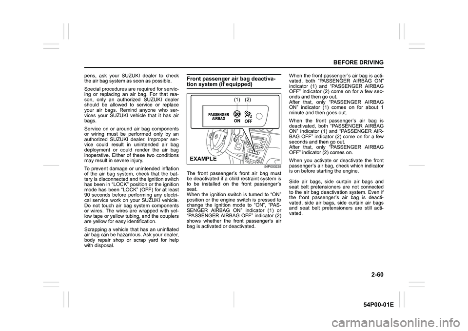
54P000228
The front passenger’s front air bag must
be deactivated if a child restraint system is
to be installed on the front passenger’s
seat.
When the ignition switch is turned to “ON”
position or the engine switch is pressed to
change the ignition mode to “ON”, “PAS-
SENGER AIRBAG ON” indicator (1) or
“PASSENGER AIRBAG OFF” indicator (2)
shows whether the front passenger’s air
bag is activated or deactivated.When the front passenger’s air bag is acti-
vated, both “PASSENGER AIRBAG ON”
indicator (1) and “PASSENGER AIRBAG
OFF” indicator (2) come on for a few sec-
onds and then go out.
After that, only “PASSENGER AIRBAG
ON” indicator (1) comes on for about 1
minute and then goes out.
When the front passenger’s air bag is
deactivated, both “PASSENGER AIRBAG
ON” indicator (1) and “PASSENGER AIR-
BAG OFF” indicator (2) come on for a few
seconds and then go out.
After that, only “PASSENGER AIRBAG
OFF” indicator (2) comes on.
When you activate or deactivate the front
passenger’s air bag, check which indicator
is on before starting the engine.
Side air bags, side curtain air bags and
seat belt pretensioners are not connected
to the air bag deactivation system. Even if
the front passenger’s air bag is deacti-
vated, side air bags, side curtain air bags
and seat belt pretensioners are still acti-
vated.
(1)(2)
EXAMPLE
Page 83 of 482
2-61
BEFORE DRIVING
54P00-01E
58MS030
According to accident statistics, children
are safer when properly restrained in rear
seating positions than front seating posi-
tions. Whenever possible, SUZUKI recom-
mends that child restraint systems be
installed on the rear seat.
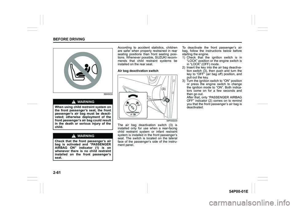
Air bag deactivation switch
54P000229
The air bag deactivation switch (3) is
installed only for use when a rear-facing
child restraint system or infant restraint
system is installed in the front passenger’s
seat. The switch is located on the lateral
face of the passenger’s side of the instru-
ment panel.To deactivate the front passenger’s air
bag, follow the instructions below before
starting the engine.
1) Check that the ignition switch is in
“LOCK” position or the engine switch is
in “LOCK” (OFF) mode.
2) Insert the key into the air bag deactiva-
tion switch (3), then push and turn the
key to “OFF” (air bag off) position, and
pull out the key.
3) Turn the ignition switch to “ON” position
or press the engine switch to change
the ignition mode to “ON”. Both indica-
tors come on for a few seconds and
then go out.
After that, only “PASSENGER AIRBAG
OFF” indicator (2) comes on to remind
you that the front passenger’s air bag is
deactivated.
WA R N I N G
When using child restraint system on
the front passenger’s seat, the front
passenger’s air bag must be deacti-
vated; otherwise deployment of the
front passenger’s air bag could result
in the death or serious injury of the
child.
WA R N I N G
Check that the front passenger’s air
bag is activated and “PASSENGER
AIRBAG ON” indicator (1) is on
whenever there is no child restraint
installed on the front passenger’s
seat.
(3)
Page 84 of 482
2-62
BEFORE DRIVING
54P00-01E
To activate the front passenger’s air bag,
follow the instructions below before start-
ing the engine.
1) Check that the ignition switch is in
“LOCK” position or the engine switch is
in “LOCK” (OFF) mode.
2) Insert the key into the air bag deactiva-
tion switch (3), then push and turn the
key to “ON” (air bag on) position, and
pull out the key.
3) Turn the ignition switch to “ON” position
or press the engine switch to change
the ignition mode to “ON”. Both indica-
tors come on for a few seconds and
then go out.
After that, only “PASSENGER AIRBAG
ON” indicator (1) comes on for about 1
minute and then goes out to remind you
that the front passenger’s air bag is
activated.
Page 85 of 482
2-63
BEFORE DRIVING
54P00-01E
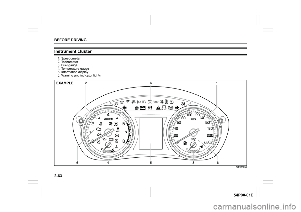
Instrument cluster
1. Speedometer
2. Tachometer
3. Fuel gauge
4. Temperature gauge
5. Information display
6. Warning and indicator lights
54P000230
21 6
64 5 36EXAMPLE
Page 86 of 482
2-64
BEFORE DRIVING
54P00-01E
Speedometer
The speedometer indicates vehicle speed.
Tachometer
The tachometer indicates engine speed in
revolutions per minute.
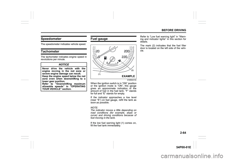
Fuel gauge
61MM0A154
When the ignition switch is in “ON” position
or the ignition mode is “ON”, this gauge
gives an approximate indication of the
amount of fuel in the fuel tank. “F” stands
for full and “E” stands for empty.
If the indicator approaches a low level
(near “E”) on fuel gauge, refill the tank as
soon as possible.
NOTE:
The indicator moves a little depending on
road conditions (for example, slope or
curve) and driving conditions because of
fuel moving in the tank.
If the low fuel warning light (1) comes on,
fill the fuel tank immediately.Refer to “Low fuel warning light” in “Warn-
ing and indicator lights” in this section for
details.
The mark (2) indicates that the fuel filler
door is located on the left side of the vehi-
cle.
NOTICE
Never drive the vehicle with the
engine revving in the red zone or
severe engine damage can result.
Keep the engine speed below the red
zone even when downshifting to a
lower gear position.
Refer to “Downshifting maximum
allowable speeds” in “OPERATING
YOUR VEHICLE” section.(2)
(1)EXAMPLE
Page 87 of 482
2-65
BEFORE DRIVING
54P00-01E
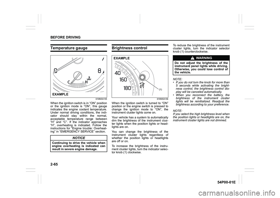
Temperature gauge
61MM0A155
When the ignition switch is in “ON” position
or the ignition mode is “ON”, this gauge
indicates the engine coolant temperature.
Under normal driving conditions, the indi-
cator should stay within the normal,
acceptable temperature range between
“H” and “C”. If the indicator approaches
“H”, overheating is indicated. Follow the
instructions for “Engine trouble: Overheat-
ing” in “EMERGENCY SERVICE” section.
Brightness control
61MM0A156
When the ignition switch is turned to “ON”
position or the engine switch is pressed to
change the ignition mode to “ON”, the
instrument cluster lights come on.
Your vehicle has a system to automatically
dim the brightness of the instrument clus-
ter lights when the position lights or head-
lights are on.
You can change the brightness of the
instrument cluster lights regardless of
whether the position lights or headlights
are off or on.
To increase the brightness of the instru-
ment cluster lights, turn the indicator selec-
tor knob (1) clockwise. To reduce the brightness of the instrument
cluster lights, turn the indicator selector
knob (1) counterclockwise.
NOTE:
• If you do not turn the knob for more than
5 seconds while activating the bright-
ness control, the brightness control dis-
play will be canceled automatically.
• When you reconnect the battery, the
brightness of the instrument cluster
lights will be reinitialized. Readjust the
brightness according to your preference.
NOTE:
If you select the high brightness level when
the position lights or headlights are on, the
instrument cluster lights are not dimmed.
NOTICE
Continuing to drive the vehicle when
engine overheating is indicated can
result in severe engine damage.
EXAMPLE
(1)
EXAMPLEWA R N I N G
Do not adjust the brightness of the
instrument panel lights while driving.
Otherwise, you could lose control of
the vehicle.
Page 88 of 482
2-66
BEFORE DRIVING
54P00-01E
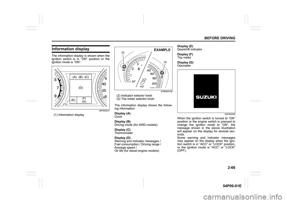
Information display
The information display is shown when the
ignition switch is in “ON” position or the
ignition mode is “ON”.
54P000231
(1) Information display
61MM0A158
(2) Indicator selector knob
(3) Trip meter selector knob
The information display shows the follow-
ing information.
Display (A)
Clock
Display (B)
Driving mode (for 4WD models)
Display (C)
Thermometer
Display (D)
Warning and indicator messages /
Fuel consumption / Driving range /
Average speed /
Oil life (for diesel engine models)Display (E)
Gearshift indicator
Display (F)
Trip meter
Display (G)
Odometer
54P000256
When the ignition switch is turned to “ON”
position or the engine switch is pressed to
change the ignition mode to “ON”, the
message shown in the above illustration
will appear on the display for several sec-
onds.
Some warning and indicator messages
may appear on the display when the igni-
tion switch is in “ACC” or “LOCK” position,
or the ignition mode is “ACC” or “LOCK”
(OFF).
(1)(A) (B) (C)
(D)
(E)
(F)
(G)
(3)
(2)
EXAMPLE
Page 89 of 482
2-67
BEFORE DRIVING
54P00-01E
Clock
The display (A) shows the time.
To set the clock, follow “Setting mode”
instructions in this section.
Driving mode (for 4WD models)
The display (B) shows the driving mode.
For details on how to use the four-mode
4WD system, refer to “Four-mode 4WD
system (if equipped)” in “OPERATING
YOUR VEHICLE” section.
Thermometer
The display (C) shows the thermometer.
The thermometer indicates the outside
temperature.
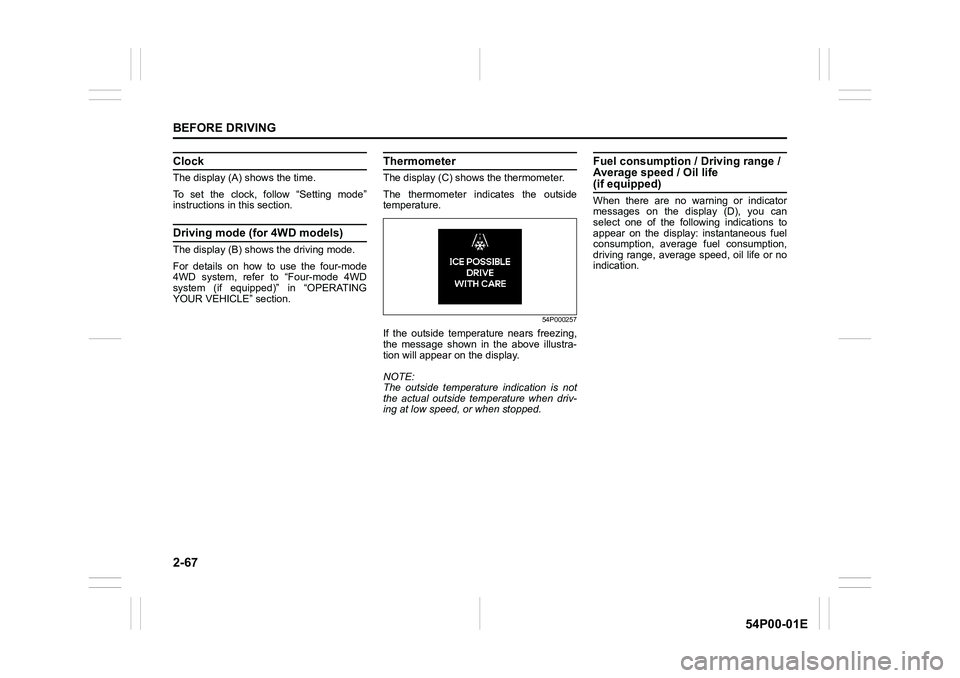
54P000257
If the outside temperature nears freezing,
the message shown in the above illustra-
tion will appear on the display.
NOTE:
The outside temperature indication is not
the actual outside temperature when driv-
ing at low speed, or when stopped.
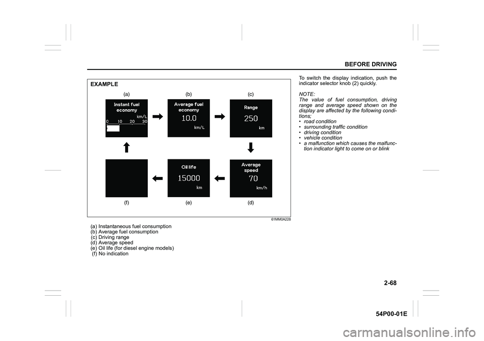
Fuel consumption / Driving range /
Average speed / Oil life
(if equipped)
When there are no warning or indicator
messages on the display (D), you can
select one of the following indications to
appear on the display: instantaneous fuel
consumption, average fuel consumption,
driving range, average speed, oil life or no
indication.
Page 90 of 482
2-68
BEFORE DRIVING
54P00-01E
61MM0A228
(a) Instantaneous fuel consumption
(b) Average fuel consumption
(c) Driving range
(d) Average speed
(e) Oil life (for diesel engine models)
(f) No indication
(a) (b) (c)
(d) (e) (f)
EXAMPLE
To switch the display indication, push the
indicator selector knob (2) quickly.
NOTE:
The value of fuel consumption, driving
range and average speed shown on the
display are affected by the following condi-
tions;
• road condition
• surrounding traffic condition
• driving condition
• vehicle condition
• a malfunction which causes the malfunc-
tion indicator light to come on or blink