ECU SUZUKI IGNIS 2017 User Guide
[x] Cancel search | Manufacturer: SUZUKI, Model Year: 2017, Model line: IGNIS, Model: SUZUKI IGNIS 2017Pages: 505, PDF Size: 8.36 MB
Page 72 of 505
2-49BEFORE DRIVING
75RM4-01E
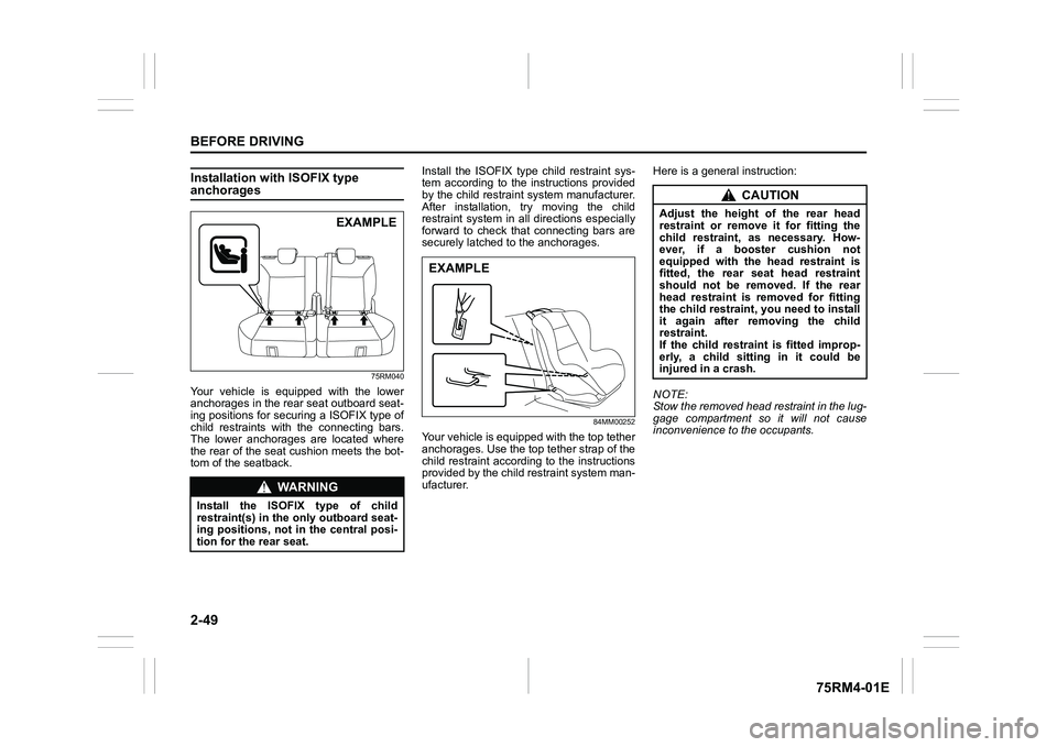
Installation with ISOFIX type anchorages
75RM040
Your vehicle is equipped with the lower
anchorages in the rear seat outboard seat-
ing positions for securing a ISOFIX type of
child restraints with the connecting bars.
The lower anchorages are located where
the rear of the seat cushion meets the bot-
tom of the seatback.Install the ISOFIX type child restraint sys-
tem according to the instructions provided
by the child restraint system manufacturer.
After installation, try moving the child
restraint system in all
directions especially
forward to check that connecting bars are
securely latched t o the anchorages.
84MM00252
Your vehicle is equipped with the top tether
anchorages. Use the top tether strap of the
child restraint according to the instructions
provided by the child restraint system man-
ufacturer. Here is a genera
l instruction:
NOTE:
Stow the removed head restraint in the lug-
gage compartment so it will not cause
inconvenience to the occupants.
WA R N I N G
Install the ISOFIX type of child
restraint(s) in the o nly outboard seat-
ing positions, not in the central posi-
tion for the rear seat.
EXAMPLE
EXAMPLE
CAUTION
Adjust the height of the rear head
restraint or remove it for fitting the
child restraint, as necessary. How-
ever, if a booster cushion not
equipped with the head restraint is
fitted, the rear seat head restraint
should not be removed. If the rear
head restraint is removed for fitting
the child restraint, you need to install
it again after removing the child
restraint.
If the child restraint is fitted improp-
erly, a child sitting in it could be
injured in a crash.
Page 73 of 505
2-50
BEFORE DRIVING
75RM4-01E
78F114
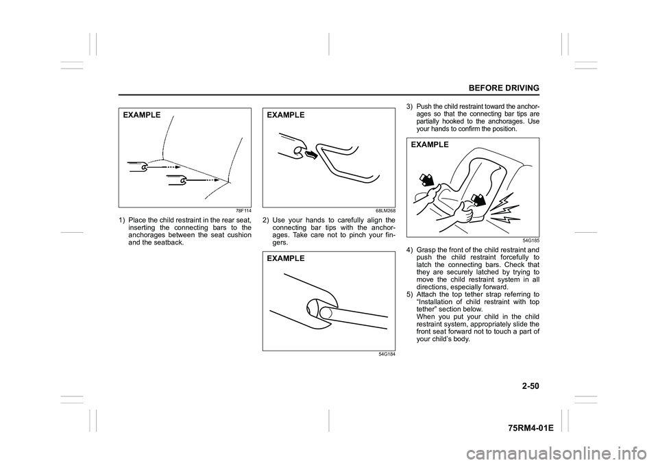
1) Place the child restraint in the rear seat,inserting the connecting bars to the
anchorages between the seat cushion
and the seatback.
68LM268
2) Use your hands to carefully align theconnecting bar tips with the anchor-
ages. Take care not to pinch your fin-
gers.
54G184
3) Push the child restraint toward the anchor- ages so that the connecting bar tips are
partially hooked to the anchorages. Use
your hands to confirm the position.
54G185
4) Grasp the front of the child restraint and
push the child restraint forcefully to
latch the connecting bars. Check that
they are securely latched by trying to
move the child restraint system in all
directions, especially forward.
5) Attach the top tether strap referring to
“Installation of child restraint with top
tether” section below.
When you put your child in the child
restraint system, appropriately slide the
front seat forward not to touch a part of
your child’s body.
EXAMPLE
EXAMPLEEXAMPLE
EXAMPLE
Page 74 of 505
2-51BEFORE DRIVING
75RM4-01E
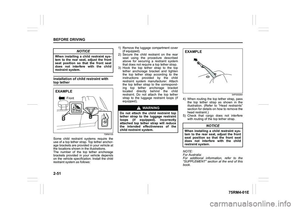
Installation of child restraint with top tether
75RM105
Some child restraint systems require the
use of a top tether strap. Top tether anchor-
age brackets are provided in your vehicle at
the locations shown in the illustrations.
The number of the top tether anchorage
brackets provided in your vehicle depends
on the vehicle specification. Install the child
restraint system as follows:
1) Remove the luggage compartment cover
(if equipped).2) Secure the child restraint on the rear
seat using the procedure described
above for securing a restraint system
that does not require a top tether strap.
3) Hook the top tether strap to the top tether anchorage bracket and tighten
the top tether strap according to the
instructions provided by the child
restraint system manufacturer. Attach
the top tether strap to the correspond-
ing top tether anchorage bracket
located directly behind the child
restraint. Do not attach the top tether
strap to the luggage restraint loops (if
equipped).
54P000264
4) When routing the top tether strap, passthe top tether strap as shown in the
illustration. (Refer to “Head restraints”
section for details on how to remove the
head restraint.)
5) Check that cargo does not interfere with routing of the top tether strap.
NOTE:
For Australia:
For additional information, refer to the
“SUPPLEMENT” section at the end of this
book.
NOTICE
When installing a child restraint sys-
tem to the rear seat, adjust the front
seat position so that the front seat
does not interfer e with the child
restraint system.EXAMPLE
Front
WA R N I N G
Do not attach the child restraint top
tether strap t o the luggage restraint
loops (if equipped). Incorrectly
attached top tether strap will reduce
the intended effectiveness of the
child restraint system.
NOTICE
When installing a child restraint sys-
tem to the rear seat, adjust the front
seat position so that the front seat
does not interfer e with the child
restraint system.EXAMPLE
Page 80 of 505
2-57BEFORE DRIVING
75RM4-01E
Refer to “Seat belts and child restraint sys-
tems” section for details on securing your
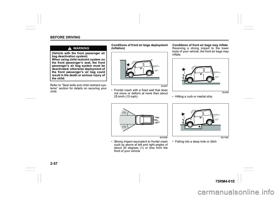
child. Conditions of front
air bags deployment
(inflation)
80J097
• Frontal crash with a fixed wall that does not move or deform at more than about
25 km/h (15 mph)
80J098E
• Strong impact equivalent to frontal crashsuch as above at left and right angles of
about 30 degrees (1) or less from the
front of your vehicle Conditions of front air bags may inflate
Receiving a strong impact to the lower
body of your vehicle, the front air bags may
inflate.
80J099
• Hitting a curb or medial strip
80J100E
• Falling into a deep hole or ditch
WA R N I N G
(Vehicle with the front passenger air
bag deactivation system)
When using child restraint system on
the front passenger’s seat, the front
passenger’s air bag system must be
deactivated; otherwise deployment of
the front passenger’s air bag could
result in the death or serious injury of
the child.
(1)
(1)
Page 151 of 505

2-128
BEFORE DRIVING
75RM4-01E
Tilt steering lock lever
75RM044
(1) LOCK
(2) UNLOCK
The lock lever is located under the steering
column. To adjust the steering wheel
height:
1) Push down the lock lever to unlock the
steering column.
2) Adjust the steering wheel to the desired height and lock the steering column by
pulling up the lock lever.
3) Try moving the steering wheel up and down to check that it is securely locked
in position.
Horn
75RM045
Press the horn button of the steering wheel
to sound the horn. The horn will sound with
the ignition switch in any position or any
ignition mode.
(1)
(2)
EXAMPLE
WA R N I N G
Never attempt to adjust the steering
wheel while the vehicle is moving or
you could lose contr ol of the vehicle.
EXAMPLE
Page 155 of 505
3-2
OPERATING YOUR VEHICLE
75RM4-01E
NOTE:
It is normal for water to drip from the air
conditioning system after use.
4) Check that the hood is fully closed andlatched.
5) Check the headlights, turn signal lights, brake lights and horn for proper opera-
tion.
6) Adjust the seat and head restraint.
7) Check the brake pedal and the parking brake lever.
8) Adjust the mirrors.
9) Check that you and all passengers have properly fastened your seat belts.
10)Check that all warning lights come on as the ignition switch is turned to “ON”
position or the engine switch is pressed
to change the ignition mode to ON.
11)Check all gauges.
12)Check that the brake system warning light turns off when the parking brake is
released.
Once a week, or each time you fill your fuel
tank, perform the following under-hood
checks:
1) Engine oil level
2) Coolant level
3) Brake fluid level
4) Lead-acid battery solution level
5) Windshield washer fluid level
6) Hood latch operation Pull the hood release handle inside the
vehicle. Check that you cannot open the hood all the way without releasing
the secondary latch. Close the hood
securely after checking for proper latch
operation. See the item “All latches,
hinges and locks” of “Chassis, body
and others” in “Maintenance schedule”
in the “INSPECTION AND MAINTE-
NANCE” section for lubrication sched-
ule.
Once a month, or each time you fill your
fuel tank, check the tire pressure using a
tire pressure gauge. Also check the tire
pressure of the spare tire.
Engine oil consumptionIt is normal for the engine to consume
some engine oil during normal vehicle
operation.
The amount of engine oil consumption
depends on viscosity and quality of the oil
and your driving conditions.
More oil is consumed during high-speed
driving and when there is frequent acceler-
ation and deceleration. Under high loads,
your engine also will consume more oil.
A new engine also consumes more oil,
since its pistons, piston rings and cylinder
walls have not yet become conditioned.
New engines reach the normal level of oil
consumption only after approximately
5000 km (3000 miles) driving.
Oil consumption:
Max. 1.0 L per 1000 km
(1 Qt. per 600 miles)
When judging the amount of oil consump-
tion, note that the oil may become diluted
and it is difficult to judge the accurate oil
level.
As an example, if a vehicle is used for
repeated short trips, and consumes a nor-
mal amount of oil, the dipstick may not
show any drop in the oil level at all, even
after 1000 km (600 miles) or more of driv-
ing. This is because the oil gradually
becomes diluted with fuel or moisture,
WA R N I N G
Check that the hood is fully closed
and latched before d riving. If it is not,
it can fly up unexpectedly during
driving, obstructing your view and
resulting in an accident.
Page 163 of 505
3-10
OPERATING YOUR VEHICLE
75RM4-01E
NOTE:
• Even when the remote controller is in theinterior workable area, if it is in any of the
following conditions, you may not be
able to start the engine or select the igni-
tion modes, and the REMOTE CON-
TROLLER OUTSIDE warning may be
given.
– The remote controller’s battery is low.
– The remote controller is affected by strong radio signals or noise.
– The remote controller is in contact with
or covered by a metallic object.
– The remote controller is in stowage such as the glove box or a door
pocket.
– The remote controller is in the sun
visor pocket or on the floor.
• Even when the remote controller is out- side the interior workable area, if it is in
any of the following conditions, you may
be able to start the engine or select the
ignition mode. The REMOTE CON-
TROLLER OUTSIDE warning may not
be given at that time.
– The remote controller is outside the
vehicle but very close to a door.
– The remote controller is on the instru-
ment panel.
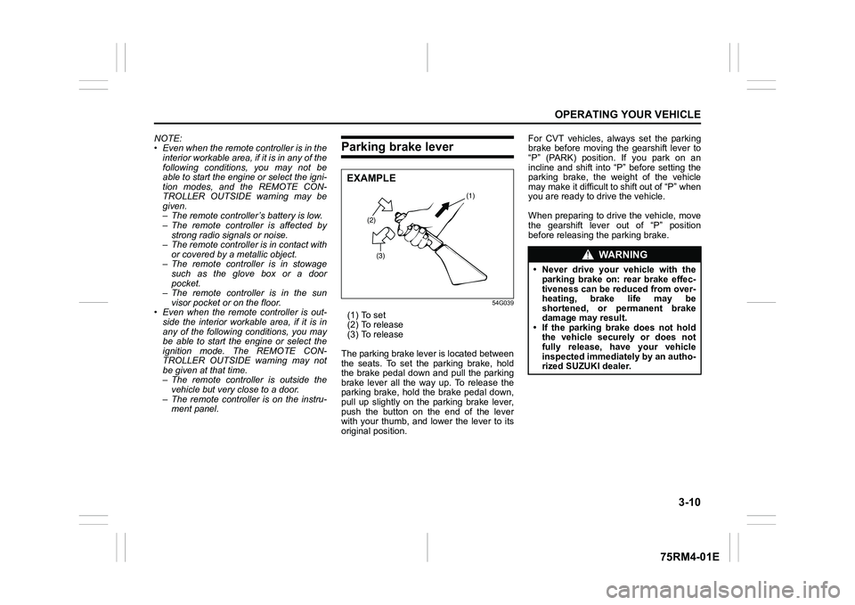
Parking brake lever
54G039
(1) To set
(2) To release
(3) To release
The parking brake lever is located between
the seats. To set the parking brake, hold
the brake pedal down and pull the parking
brake lever all the way up. To release the
parking brake, hold the brake pedal down,
pull up slightly on the parking brake lever,
push the button on the end of the lever
with your thumb, and lower the lever to its
original position. For CVT vehicles, always set the parking
brake before moving the gearshift lever to
“P” (PARK) position. If you park on an
incline and shift into “P” before setting the
parking brake, the weight of the vehicle
may make it difficult to shift out of “P” when
you are ready to drive the vehicle.
When preparing to drive the vehicle, move
the gearshift lever out of “P” position
before releasing the parking brake.
(2)
(3) (1)
EXAMPLE
WA R N I N G
• Never drive your vehicle with the
parking brake on: rear brake effec-
tiveness can be reduced from over-
heating, brake life may be
shortened, or permanent brake
damage may result.
• If the parking brake does not hold the vehicle securely or does not
fully release, have your vehicle
inspected immediately by an autho-
rized SUZUKI dealer.
Page 182 of 505
3-29OPERATING YOUR VEHICLE
75RM4-01E
possible. However, if downshifting more
than 3 steps, gear shifting will take more
time.
• When the gear is shifting, a noise can be heard in some case. This is not malfunc-
tion. Starting off:
1) Start the engine as instructed in “Start-
ing the engine” in this section.
2) With your foot on the brake pedal, shift the gearshift lever to the “M” position.
When the gearshift lever is shifted to
the “M” position, the gear will be shifted
to 1st. Before starting off, always make
sure that the intended gear is engaged
by checking the gear position indicator,
then depress the accelerator pedal.
NOTE:
• If 1st gear cannot be engaged even though the gearshift lever has been
shifted from the “N” to the “M” position,
the system will re-try shifting automati-
cally. This will take some time, noise
may be heard from the gears, and shift-
ing gear shock may occur. However,
they do not indicate malfunction.
• The “N” indicator will flush, the depress brake pedal indicator will come on and a
warning buzzer (long pulse sound) will
sound if any of the following cases
occur;
– If you shift the gearshift lever from the “N” to the “M” position without
depressing the brake pedal
– If the system is unable to re-try shifting
You should depress the brake pedal and
shift the gearshift lever to “N” position,
then shift to “M” position again a few
seconds later.
WA R N I N G
• Be careful when accelerating, upshifting, downshifting or braking
on a slippery surface. Sudden
acceleration or engine braking
could cause the vehicle to spin or
skid.
• To drive down a long or steep hill,
reduce your speed and downshift.
Remember, if you ride the brakes
excessively, they may overheat and
fail.
• While driving the vehicle, do not shift the gearshift lever to “N” posi-
tion. The engine brake may not
work and you may get involved in
an unexpected accident. If you
return the gearshift lever from “N”
to “M” because of unintended shift-
ing, the gear position will be shifted
according to the current vehicle
speed.
• Do not apply the parking brake
while driving. Otherwise, it could
cause a skid and you may get
involved in an unexpected acci-
dent.
NOTICE
• If the gearshift lever cannot shiftinto any position, or the gear is
changed to “N” position automati-
cally when the vehicle speed
becomes less than 10 km/h (6
mph), there may be a systematic
malfunction. In this case, ask your
SUZUKI dealer to inspect the Auto
Gear Shift system as soon as pos-
sible.
• The manual (M) mode does not
upshift even if the engine speed
reaches the rev-limit.
• The system will not allow shifting up or down to a gear that would
cause engine over-revving or
under-revving.
• If frequently driving at low speed using a high gear position, the life
cycle of the clutch may be reduced.
• Frequent downshif ting (more than
3 positions consecutively) causes
the reduction of transaxle life.
Page 192 of 505
3-39OPERATING YOUR VEHICLE
75RM4-01E
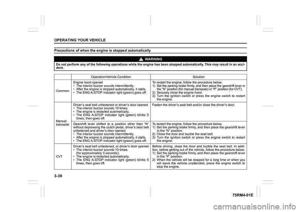
Precautions of when the engine is stopped automatically
WA R N I N G
Do not perform any of the following operations while the engine has been stopped automatically. This may result in an acci-
dent.
Operation/Vehicle Condition Solution
Common Engine hood opened
• The interior buzzer sounds intermittently.
• After the engine is stopped automatically, it stalls.
• The ENG A-STOP indicator light (green) goes off. To restart the engine, follow the procedure below.
1) Set the parking brake firmly, and then place the gearshift le
ver in
the “N” position (for m anual transaxle) or “P” position (for CVT).
2) Securely close the engine hood.
3) Turn the ignition switch or press the engine switch to restar t
the engine.
Manual
transaxle Driver’s seat belt unfast
ened or driver’s door opened
• The interior buzze r sounds 10 times.
• The engine is restarted automatically.
• The ENG A-STOP indicator light (green) blinks 5 times, then goes off. Fasten the driver’s seat belt
and/or close the driver’s door.
Gearshift lever shifted to a position other than “N”
without depressing the clutch pedal, driver’s seat belt
unfastened and driver’s door opened
• The interior buzzer sounds intermittently.
• After the engine is stopped automatically, it stalls.
• The ENG A-STOP indicator light (green) goes off. To restart the engine, follow the procedure below.
1) Set the parking brake firmly, a
nd then place the gearshift lever
in the “N” position.
2) Close the door and bu ckle the seat belt.
3) Turn the ignition switch or press the engine switch to restar t
the engine.
CVT Driver’s seat belt unfasten
ed, or driver’s door opened
• The interior buzzer sounds 10 times.
(for approximately 5 seconds).
• The engine is restarted automatically.
• The ENG A-STOP indicator light (green) blinks 5 times, then goes off. Before driving, close the door and buckle the seat belt. In add
i-
tion, before getting out of the vehicle, follow the procedure b elow.
1) Set the parking brake firmly, a nd then place the gearshift lever
in the “P” position.
2) When the vehicle will be stopped for a long time or when you will leave the vehicle unattended, press the engine switch to
stop the engine.
Page 194 of 505
3-41OPERATING YOUR VEHICLE
75RM4-01E
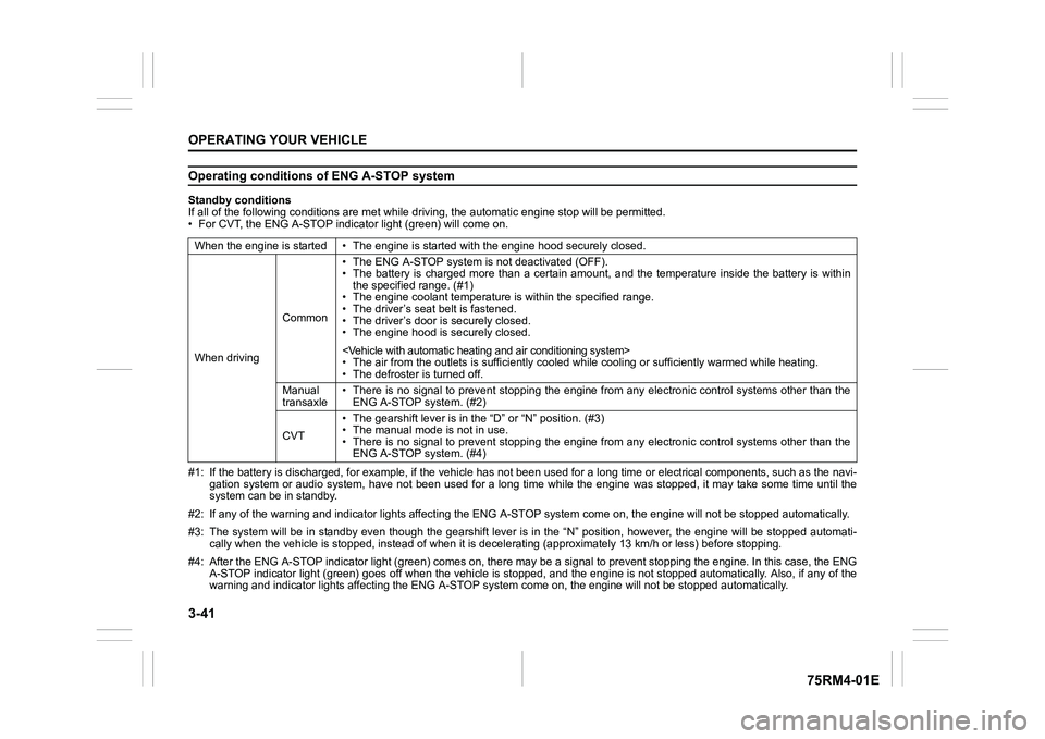
Operating conditions of ENG A-STOP systemStandby conditions
If all of the following conditions are met while driving, the automatic engine stop will be permitted.
• For CVT, the ENG A-STOP indicator light (green) will come on.
#1: If the battery is discharged, for example, if the vehicle has not been used for a long time or electrical components, such as the navi-
gation system or audio system, have not been used for a long ti me while the engine was stopped, it may take some time until th e
system can be in standby.
#2: If any of the warning and indi cator lights affecting the ENG A-STOP system come on, the e ngine will not be stopped automati cally.
#3: The system will be in standby even though the gearshift leve r is in the “N” position, however, the engine will be stopped automati-
cally when the vehicl e is stopped, instead of when it is decelerating (approximately 13 km/ h or less) before stopping.
#4: After the ENG A-STOP indicator light (green) comes on, there may be a signal to prevent stopping the engine. In this case, the ENG
A-STOP indicator light (green) goes off when the vehicle is sto pped, and the engine is not stopped automatically. Also, if any of the
warning and indi cator lights affecting the ENG A-STOP system co me on, the engine will not be stopped automatically.
When the engine is started • The
engine is started with the engine hood securely closed.
When driving Common• The ENG A-STOP system is
not deactivated (OFF).
• The battery is charged more than a certain amount, and the tem perature inside the battery is within
the specified range. (#1)
• The engine coolant temperature i s within the specified range.
• The driver’s seat belt is fastened.
• The driver’s door is securely closed.
• The engine hood is s ecurely closed.
• The air from the outlets is su fficiently cooled while cooling or sufficiently warmed while heating.
• The defroster is turned off.
Manual
transaxle • There is no signal to prevent stopping the engine from any ele
ctronic control systems other than the
ENG A-STOP system. (#2)
CVT • The gearshift lever is in the
“D” or “N” position. (#3)
• The manual mode is not in use.
• There is no signal to prevent stopping the engine from any ele ctronic control systems other than the
ENG A-STOP system. (#4)