handle SUZUKI IGNIS 2017 Owner's Manual
[x] Cancel search | Manufacturer: SUZUKI, Model Year: 2017, Model line: IGNIS, Model: SUZUKI IGNIS 2017Pages: 505, PDF Size: 8.36 MB
Page 382 of 505
7-33INSPECTION AND MAINTENANCE
75RM4-01E
75F086
81PN159 75RM370
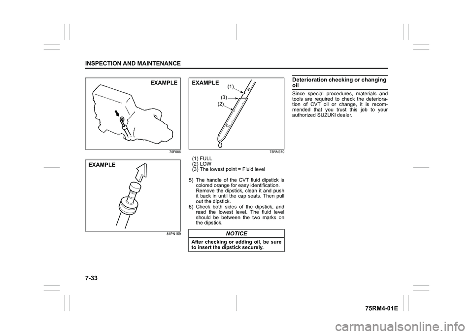
(1) FULL
(2) LOW
(3) The lowest point = Fluid level
5) The handle of the CVT fluid dipstick is colored orange for ea sy identification.
Remove the dipstick, clean it and push
it back in until the cap seats. Then pull
out the dipstick.
6) Check both sides of the dipstick, and read the lowest level. The fluid level
should be between the two marks on
the dipstick.
Deterioration checking or changing oilSince special procedures, materials and
tools are required to check the deteriora-
tion of CVT oil or change, it is recom-
mended that you trust this job to your
authorized SUZUKI dealer.
EXAMPLE
EXAMPLE
NOTICE
After checking or adding oil, be sure
to insert the di pstick securely.
(3)
(1)
(2)
C
H
(ΟΝ03/(
Page 390 of 505
7-41INSPECTION AND MAINTENANCE
75RM4-01E
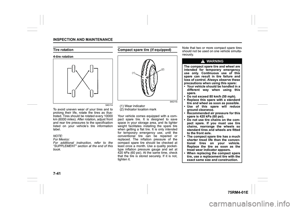
Tire rotation4-tire rotation
54G114
To avoid uneven wear of your tires and to
prolong their life, rotate the tires as illus-
trated. Tires should be rotated every 10000
km (6000 miles). After rotation, adjust front
and rear tire pressures to the specification
listed on your vehicle’s tire information
label.
NOTE:
For Mexico:
For additional instruction, refer to the
“SUPPLEMENT” section at the end of this
book.
Compact spare tire (if equipped)
54G115
(1) Wear indicator
(2) Indicator location mark
Your vehicle comes equipped with a com-
pact spare tire. It is designed to save
space in your storage area, and its lighter
weight facilitates installing the spare tire
when getting a flat tire. It is only intended
for temporary emergency use, until the
conventional tire can be repaired or
replaced. The inflation pressure of the
compact spare tire should be checked at
least once a month. Use a quality pocket-
type inflation pressure gauge and set at
420 kPa (60 psi). At the same time, check
that the tire is stored securely. If it is not,
tighten it. Note that two or more compact spare tires
should not be used on one vehicle simulta-
neously.
WA R N I N G
The compact spare tire and wheel are
intended for temporary emergency
use only. Continuous use of this
spare can result in tire failure and
loss of control. Always observe these
precautions when using this spare:
• Your vehicle should be handled in a
different way when using this
spare.
• Do not exceed 80 km/h (50 mph).
• Replace this spare with a standard tire and wheel as soon as possible.
• Use of this spare will reduce
ground clearance.
• Recommended air pressure for this spare is 420 kPa (60 psi).
• Do not use tire chains on the com- pact spare. If you must use tire
chains, rearrange the wheels so
standard tires and wheels are fitted
to the front axle.
• The compact spare tire has a much
shorter tread life than the conven-
tional tires on your vehicle.
Replace the tire as soon as the
tread wear indicator appears.
• When replacing the compact spare tire, use a replacement tire with the
exact same size and construction.
Page 398 of 505
7-49INSPECTION AND MAINTENANCE
75RM4-01E
Bulb replacement
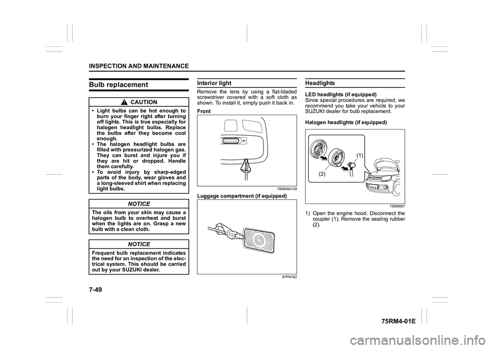
Interior lightRemove the lens by using a flat-bladed
screwdriver covered with a soft cloth as
shown. To install it, simply push it back in.
Front
76MH0A139
Luggage compartmen t (if equipped)
81PN162
HeadlightsLED headlights (if equipped)
Since special procedures are required, we
recommend you take your vehicle to your
SUZUKI dealer for bulb replacement.
Halogen headlights (if equipped)
75RM067
1) Open the engine hood. Disconnect the
coupler (1). Remove the sealing rubber
(2).
CAUTION
• Light bulbs can be hot enough to burn your finger right after turning
off lights. This is true especially for
halogen headlight bulbs. Replace
the bulbs after they become cool
enough.
• The halogen headlight bulbs are filled with pressurized halogen gas.
They can burst and injure you if
they are hit or dropped. Handle
them carefully.
• To avoid injury by sharp-edged
parts of the body, wear gloves and
a long-sleeved shirt when replacing
light bulbs.
NOTICE
The oils from your skin may cause a
halogen bulb to overheat and burst
when the lights are on. Grasp a new
bulb with a clean cloth.
NOTICE
Frequent bulb replacement indicates
the need for an inspection of the elec-
trical system. This should be carried
out by your SUZUKI dealer.
(1)
(2)
Page 410 of 505
8-1EMERGENCY SERVICE
75RM4-01E
Tire changing tool
75RM076
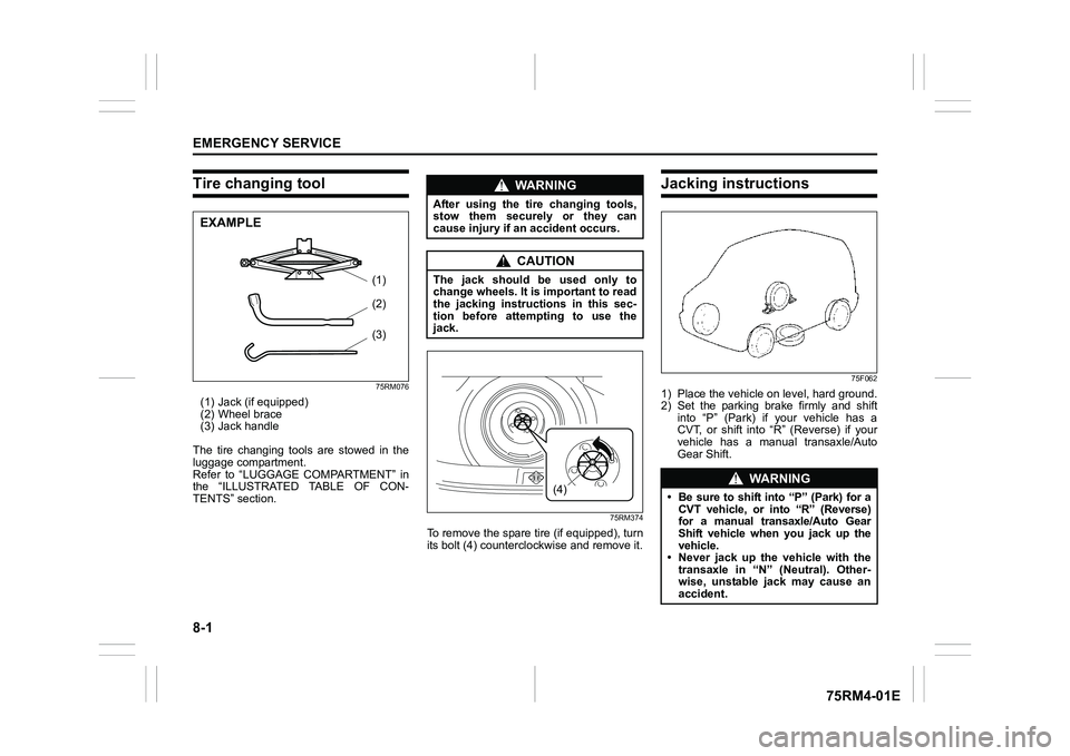
(1) Jack (if equipped)
(2) Wheel brace
(3) Jack handle
The tire changing tools are stowed in the
luggage compartment.
Refer to “LUGGAGE COMPARTMENT” in
the “ILLUSTRATED TABLE OF CON-
TENTS” section.
75RM374
To remove the spare tire (if equipped), turn
its bolt (4) countercl ockwise and remove it.
Jacking instructions
75F062
1) Place the vehicle on level, hard ground.
2) Set the parking brake firmly and shift into “P” (Park) if your vehicle has a
CVT, or shift into “R” (Reverse) if your
vehicle has a manual transaxle/Auto
Gear Shift.
(3)(2)
(1)
EXAMPLE
WA R N I N G
After using the tire changing tools,
stow them securely or they can
cause injury if an accident occurs.
CAUTION
The jack should be used only to
change wheels. It is important to read
the jacking instructions in this sec-
tion before attempting to use the
jack.
(4)
:Ν 5 1 , 1 *
Page 411 of 505
8-2
EMERGENCY SERVICE
75RM4-01E
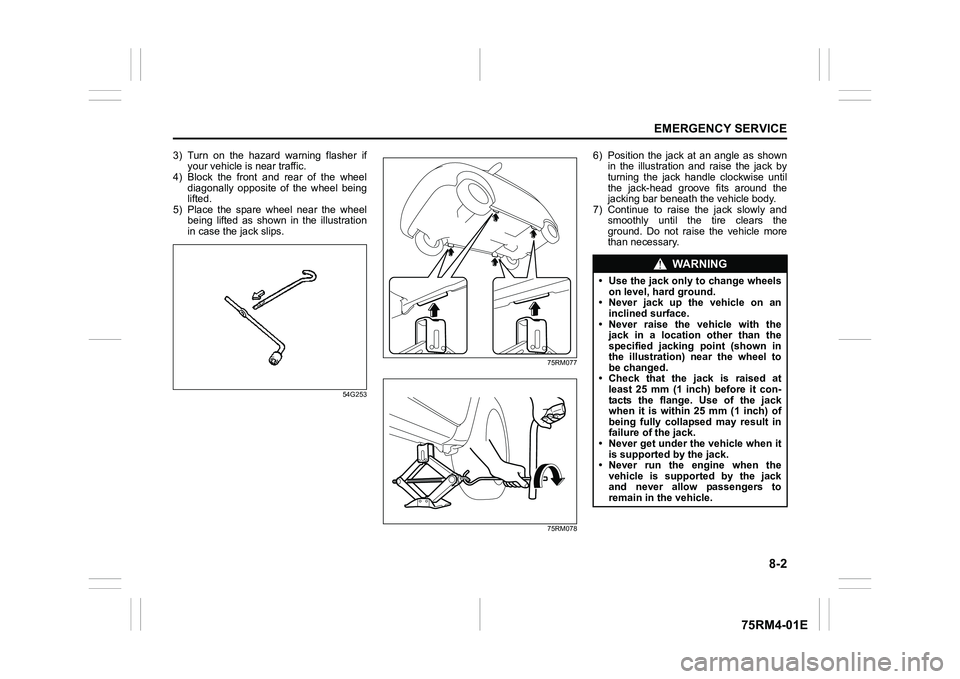
3) Turn on the hazard warning flasher ifyour vehicle is near traffic.
4) Block the front and rear of the wheel
diagonally opposite of the wheel being
lifted.
5) Place the spare wheel near the wheel
being lifted as shown in the illustration
in case the jack slips.
54G253 75RM077
75RM078
6) Position the jack at an angle as shown
in the illustration and raise the jack by
turning the jack handle clockwise until
the jack-head groove fits around the
jacking bar beneath the vehicle body.
7) Continue to raise the jack slowly and
smoothly until the tire clears the
ground. Do not raise the vehicle more
than necessary.
WA R N I N G
• Use the jack only to change wheelson level, hard ground.
• Never jack up the vehicle on an inclined surface.
• Never raise the vehicle with the jack in a location other than the
specified jacking point (shown in
the illustration) near the wheel to
be changed.
• Check that the jack is raised at
least 25 mm (1 inch) before it con-
tacts the flange. Use of the jack
when it is within 25 mm (1 inch) of
being fully collapsed may result in
failure of the jack.
• Never get under the vehicle when it
is supported by the jack.
• Never run the engine when the vehicle is supported by the jack
and never allow passengers to
remain in the vehicle.