check engine light SUZUKI IGNIS 2020 Owner's Guide
[x] Cancel search | Manufacturer: SUZUKI, Model Year: 2020, Model line: IGNIS, Model: SUZUKI IGNIS 2020Pages: 505, PDF Size: 8.36 MB
Page 213 of 505
3-60
OPERATING YOUR VEHICLE
75RM4-01E
Situations where the system may acti-
vate by chance
Under the following situations, the system
may activate.
• When there is a shadow of guard rail
• When partition lines are drawn doubly
• When there is a liner paint on the road of a construction zone because the previ-
ous line has not been erased completely
• When there is repair marks on the road or a boundary between asphalt and
snow
• When there is tire marks on snow-cov- ered or wet road
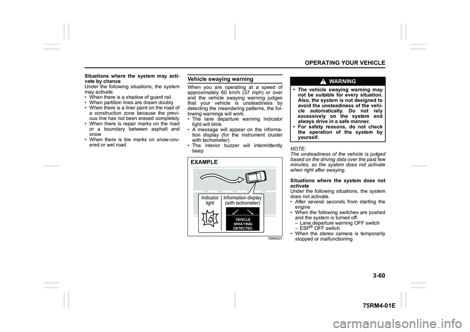
Vehicle swaying warningWhen you are operating at a speed of
approximately 60 km/h (37 mph) or over
and the vehicle swaying warning judges
that your vehicle is unsteadiness by
detecting the meandering patterns, the fol-
lowing warnings will work.
• The lane departure warning indicatorlight will blink
• A message will appear on the informa- tion display (for the instrument cluster
with tachometer)
• The interior buzzer will intermittently beep
75RM331
NOTE:
The unsteadiness of the vehicle is judged
based on the driving data over the past few
minutes, so the system does not activate
when right after swaying.
Situations where the system does not
activate
Under the following situations, the system
does not activate.
• After several seconds from starting the
engine
• When the following switches are pushed and the system is turned off:
– Lane departure warning OFF switch
– ESP
® OFF switch
• When the stereo camera is temporarily
stopped or malfunctioning
EXAMPLE
Indicator light Information display
(with tachometer)
WA R N I N G
• The vehicle swaying warning may not be suitable for every situation.
Also, the system is not designed to
avoid the unsteadiness of the vehi-
cle automatically. Do not rely
excessively on the system and
always drive in a safe manner.
• For safety reasons, do not check
the operation of the system by
yourself.
Page 219 of 505
3-66
OPERATING YOUR VEHICLE
75RM4-01E
Temporary stop of the stereo camera
Under the following situations, the function
of the stereo camera stops temporarily.
When the situations are improved, the
temporary stop of the function will be can-
celed.
• When the visibility of the stereo camerais poor
• When the temperature of the body of
stereo camera i s low or high
• When the systems related the dual cam- era brake support stops temporarily
• When the lead-acid battery has a volt- age abnormality
• When the automatic adjustment of the
stereo camera is insufficient
Failure of the stereo camera
When the stereo camera is failure, the
function of the stereo camera stops until
the ignition switch is turned to “LOCK”
position or the engine switch is pressed to
change the ignition mode to LOCK (OFF).
Find a safe place to park and turn the igni-
tion switch to “LOCK” position or change
the ignition mode to LOCK (OFF) by press-
ing the engine switch.
Restart the engine, and check that the dual
camera brake support indicator light and
lane departure warning indicator light go
off.
• If both of the indicators stay on after restarting the engine, there may be a
failure of the stereo camera. Ask your
SUZUKI dealer to have the stereo cam-
era inspected. It is thought that the cause of failure is the
followings.
• When the stereo camera has an abnor-
mality
• When the temperature of the body of stereo camera is t oo low or too high
• When the mounting position of the ste- reo camera is shifted greatly
• When there are communication abnor-
malities among the engine, transaxle
and brake controller
• When the dual camera brake support
OFF switch has an abnormality
• When the steering angle sensor has an abnormality
• When the power supply of the stereo camera is cut
NOTE:
• Under the following situations, the dual camera brake support indicator light and
lane departure warning indicator light
come on after the engine has started, it
does not indicate a malfunction. Once
the ignition switch is turned to “LOCK”
position or the engine switch is pressed
to change the ignition mode to LOCK
(OFF) and then the engine is restarted,
these indicators will go off.
– When the automatic brake system hasbeen operating 3 times
– When the automatic brake system has
been operating for long periods • The function of the stereo camera stops
if the dual camera brake support indica-
tor light and lane departure warning indi-
cator light come on and there may be a
failure of the stereo camera, but it does
not hinder normal driving.
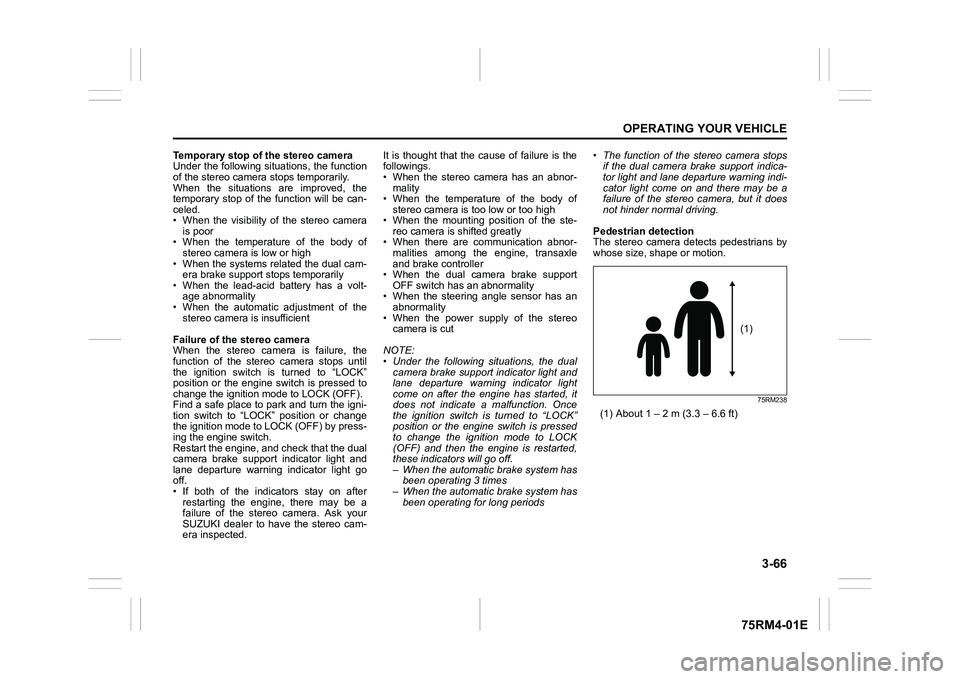
Pedestrian detection
The stereo camera detects pedestrians by
whose size, shape or motion.
75RM238
(1) About 1 – 2 m (3.3 – 6.6 ft)
(1)
Page 225 of 505
3-72
OPERATING YOUR VEHICLE
75RM4-01E
Rearview camera (if equipped)When the gearshift lever is shifted to “R”
position while the ignition switch is in “ON”
position or the ignition mode is ON, the
rearview camera system automatically
shows the view behind the vehicle on the
display.
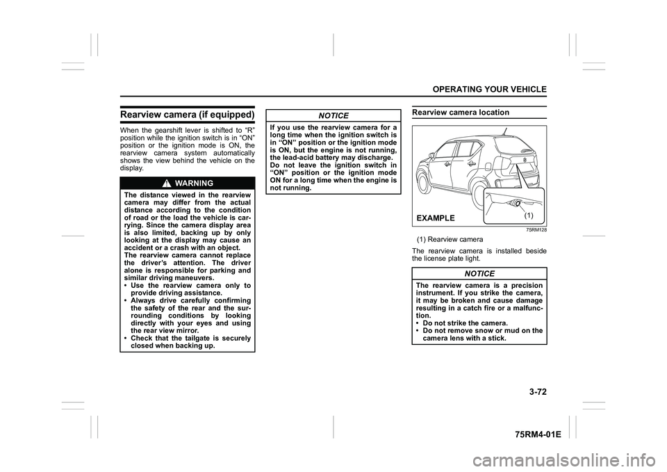
Rearview camera location
75RM128
(1) Rearview camera
The rearview camera is installed beside
the license plate light.
WA R N I N G
The distance viewed in the rearview
camera may differ from the actual
distance according to the condition
of road or the load the vehicle is car-
rying. Since the camera display area
is also limited, backing up by only
looking at the display may cause an
accident or a crash with an object.
The rearview camera cannot replace
the driver’s attention. The driver
alone is responsible for parking and
similar driving maneuvers.
• Use the rearview camera only to provide driving assistance.
• Always drive carefully confirming
the safety of the rear and the sur-
rounding conditions by looking
directly with your eyes and using
the rear view mirror.
• Check that the tailgate is securely closed when backing up.
NOTICE
If you use the rearview camera for a
long time when the ignition switch is
in “ON” position or the ignition mode
is ON, but the engine is not running,
the lead-acid battery may discharge.
Do not leave the ignition switch in
“ON” position or the ignition mode
ON for a long time when the engine is
not running.
NOTICE
The rearview camera is a precision
instrument. If you strike the camera,
it may be broken and cause damage
resulting in a catch fire or a malfunc-
tion.
• Do not strike the camera.
• Do not remove snow or mud on thecamera lens with a stick.
(1)
�(�Ο�Ν�0�3�/�(
Page 228 of 505
3-75OPERATING YOUR VEHICLE
75RM4-01E
If the rear view from the rearview cam-
era is not shown or there is a poor
image
• If the rear view from the rearview camerais not shown.
– Check that the ignition switch is in
“ON” position or the ignition mode is
ON.
– Check that the gearshift lever is
shifted to “R” position.
• If the image from the rearview camera is poor.
– Check that the camera lens is not dirty.
– Check that light from the sun or thebeam of the headlights from the vehi-
cle behind is not shining directly into
the lens.
If the rearview camera system is still not
working properly after checking the above,
have the system inspected by an autho-
rized SUZUKI dealer as soon as possible.
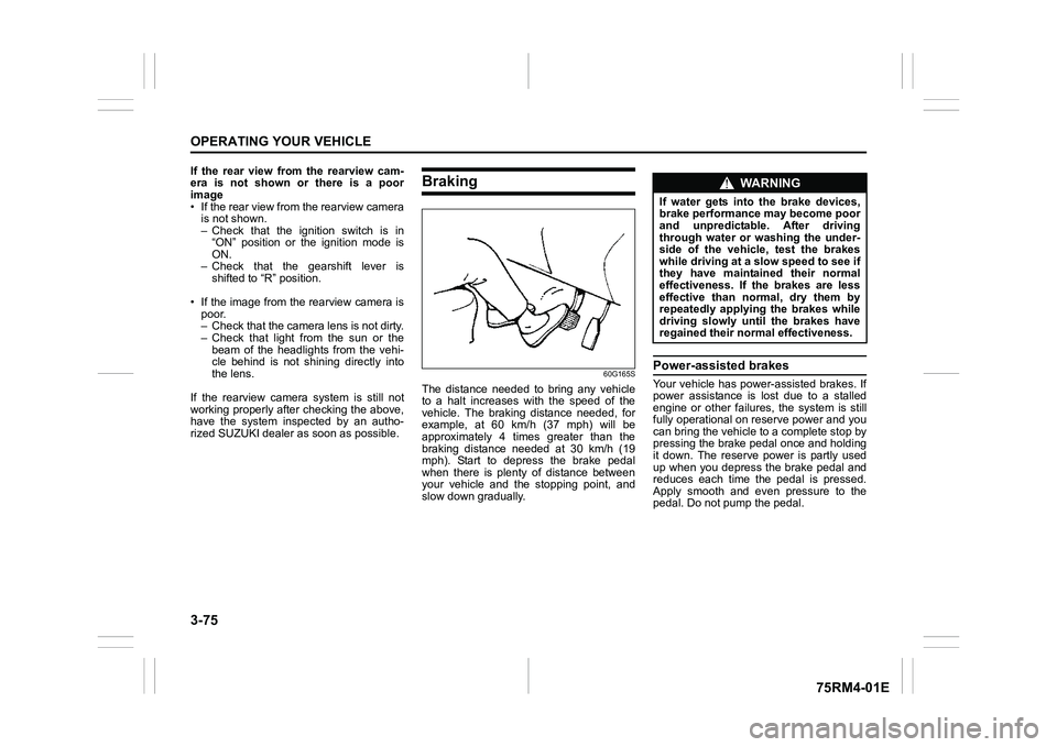
Braking
60G165S
The distance needed to bring any vehicle
to a halt increases with the speed of the
vehicle. The braking distance needed, for
example, at 60 km/h (37 mph) will be
approximately 4 times greater than the
braking distance needed at 30 km/h (19
mph). Start to depress the brake pedal
when there is plenty of distance between
your vehicle and the stopping point, and
slow down gradually.
Power-assisted brakesYour vehicle has power-assisted brakes. If
power assistance is lo st due to a stalled
engine or other failure s, the system is still
fully operational on reserve power and you
can bring the vehicle to a complete stop by
pressing the brake pedal once and holding
it down. The reserve power is partly used
up when you depress the brake pedal and
reduces each time the pedal is pressed.
Apply smooth and even pressure to the
pedal. Do not pump the pedal.
WA R N I N G
If water gets into the brake devices,
brake performance may become poor
and unpredictable. After driving
through water or washing the under-
side of the vehicle, test the brakes
while driving at a slow speed to see if
they have maintained their normal
effectiveness. If the brakes are less
effective than normal, dry them by
repeatedly applying the brakes while
driving slowly until the brakes have
regained their normal effectiveness.
Page 229 of 505
3-76
OPERATING YOUR VEHICLE
75RM4-01E
Brake assist systemWhen you slam the brakes on, the brake
assist system determines it to be an emer-
gency stop and provides more powerful
braking for a driver who cannot hold down
the brake pedal firmly.
NOTE:
If you quickly and forcefully depress the
brakes, you may hear clicking sound by
the brake assist system operation. This is
normal and indicates that the brake assist
system is activated properly.
Anti-lock brake system (ABS)ABS will help you avoid skidding by elec-
tronically controlling braking pressure. It
will also help you maintain steering control
when braking on slippery surfaces or when
braking hard.
The ABS works automatically, so you do
not need any special braking technique.
Just push the brake pedal down without
pumping. The ABS will operate whenever
it senses that the wheels are locking up.
You may feel the brake pedal move a little
while the ABS is operating.
NOTE:
• The ABS will not work if vehicle speed is under about 9 km/h (6 mph).
• If the ABS system is activated, you may
hear a clunking noise and/or feel pulsat-
ing in the brake pedal. This is normal
and indicates that the brake fluid pres-
sure is being controlled properly.
• You may hear an operation sound when you start the engine or after the vehicle
begins to move. This means that the
above systems are in the self-check
mode. This sound does not indicate a
malfunction.
WA R N I N G
Even without reserve power in the
brake system, you can still stop the
vehicle by pressing the brake pedal
harder than normally required. How-
ever, the stopping distance may be
longer.
WA R N I N G
• On some types of loose surfaces (such as gravel, snow-covered
roads, etc.), the stopping distance
required for a vehicle with ABS
may be slightly greater than the
one required for a comparable vehi-
cle with a conventional brake sys-
tem. With a conventional brake
system, skidding tires are able to
plow the gravel or snow layer,
shortening the stopping distance.
ABS minimizes this resistance
effect. Allow for extra stopping dis-
tance when driving on loose sur-
faces.
• On regular paved roads, some driv-
ers may be able to obtain slightly
shorter stopping distances with
conventional brake systems than
with ABS.
• In both of the above conditions, ABS will still offer the advantage of
helping you maintain directional
control. However, remember that
ABS will not compensate for bad
road or weather conditions or poor
driver judgment. Use good judg-
ment and do not drive too fast.
Page 232 of 505
3-79OPERATING YOUR VEHICLE
75RM4-01E
NOTE:
• If the ESP
® system is activated, you may
hear a clunking noise and/or feel pulsat-
ing in the brake pedal. This is normal
and indicates that the brake fluid pres-
sure is being controlled properly.
• You may hear an operation sound when you start the engine or after the vehicle
begins to move. This means that the
above systems are in the self-check
mode. This sound does not indicate a
malfunction. The ESP
® indicator lights are described
below:
ESP
® warning light
52KM133
This light blinks 5 times per second when
one of the following sy stems is activated.
• Stability control system
• Traction control system
• Hill descent control system (if equipped)
• Grip control system (if equipped)
If this light blinks, drive carefully.
When the ignition switch is turned to “ON”
position, or the engine switch is pressed to
change the ignition mode to ON, this light
comes on briefly so you can check that the
light is working. NOTE:
When the ESP
® warning light comes on
and stays on while driving, indicating a
malfunction of the ESP
® systems (other
than ABS), the brake system will function
as an ordinary ABS with no additional
ESP
® functions.
ESP
® OFF indicator light
57L30045
You should turn the ESP
® on during your
ordinary driving, so that you have the ben-
efits of all of the ESP
® systems.
It may be required to turn the ESP
® sys-
tems (other than ABS) off if your vehicle is
stuck in sand, mud, or snow, where wheel
spin is necessary.
WA R N I N G
(Continued)
• The ESP
® may not work properly if
the tires are excessively worn.
Replace tires when the tread wear
indicators in the grooves appear on
the tread surface.
• The ESP® is not a substitute for
winter tires or tire chains on a
snow-covered road.
WA R N I N G
• The ESP
® may not work properly if
engine related parts such as the
muffler are not equivalent to stan-
dard equipment or are extremely
deteriorated.
• Do not modify the vehicle’s sus- pension since the ESP
® may not
work properly.
NOTICE
If the ESP
® warning light comes on
and stays on while driving, there may
be a malfunction of the ESP
® sys-
tems (other than ABS). You should
have the systems inspected by an
authorized SUZUKI dealer.
Page 236 of 505
3-83OPERATING YOUR VEHICLE
75RM4-01E
Grip control system (if equipped)When one side of the tires is slipping on
slippery road surfaces such as a snow-cov-
ered road and it is difficult to start the vehi-
cle, the grip control system controls the
driving force and brake force through the
ESP
® system, and assists you in smooth
starting.
In such cases as when both of the tires are
slipping, the system may also assist start-
ing.
NOTE:
• When both of the tires are slipping, thegrip control system may work, however,
it works especially effective when one
side of the tires is slipping.
• You may hear an operation sound when you start the engine or after the vehicle
begins to move. This means that the grip
control system is in the self-check mode.
This sound does not indicate a malfunc-
tion.
• When the grip control system is working with high engine revolutions, you may
feel changing the engine speed or vehi-
cle pulsating. This is normal. Grip control switch
75RM311
(1) Grip control switch
To activate the grip control system, push
the grip control switch. An indicator light on
the switch will be lit when the grip control
system is on. When you push the switch
again, the indicator light will go off and the
grip control system will be deactivated.
• When the vehicle is stabilized and the vehicle speed exceeds about 30 km/h
(19 mph), the grip control system stops
functioning and the indicator on the
switch goes off.
• When the ESP
® system is off, the grip
control system cannot be turned on.
WA R N I N G
Grip control system has limits and
may not function properly depending
on the driving conditions. Do not rely
excessively on the system and
always drive in a safe manner.
CAUTION
• Observe the following instruc- tions. If mishandled, the grip con-
trol system cannot work properly
and may cause a malfunction.
– Inflate the tires to the recom-mended tire inflation pressure.
– When replacing tires or wheels, use only the size and type speci-
fied in this owner’s manual.
– Do not use worn or extremely uneven tires. (Continued)
CAUTION
(Continued)– Do not modify the vehicle’s sus-
pension or brake (Altering the
vehicle heig ht, etc.).
– Do not drive with extremely dete-
riorated suspension or brake.
– Do not modify the engine (Alter- ing the muffler, etc.).
– Do not equip a limited slip differ- ential.
• The grip control system may not
work properly if tires are fitted with
tire chains.
(1)
Page 237 of 505
3-84
OPERATING YOUR VEHICLE
75RM4-01E
How grip control system works
When the grip control switch is on and one
side of the tires is slipping, the grip control
system assists you in smooth starting by
controlling the driving force and brake
force of all wheels.
• When the ESP
® system is off, the grip
control system cannot be activated.
NOTE:
While the grip control system is working,
the ESP
® warning light blinks.
Hill hold control sys tem (if equipped)The hill hold control system is designed to
assist you in starting to move up hills.
When you start to move up a hill, the sys-
tem helps to prevent the vehicle from roll-
ing downward (for approximately 2
seconds) while you move your foot from
the brake pedal to the accelerator pedal.
The hill hold control system activates for a
maximum of about 2 seconds if your foot is
moved from the brake pedal when the fol-
lowing conditions are all met.
1) The gearshift lever is in a forward gear or reverse gear.
2) The parking brake is released.
3) For manual transaxle models, the clutch pedal is depressed.
4) The vehicle is o n an upward incline.
CAUTION
To activate the grip control system,
push the grip control switch and
check that the indicator on the switch
turns on.
WA R N I N G
• Do not rely excessively on the hill
hold control system. The hill hold
control system may not prevent the
vehicle from rolling downward on a
hill under all load or road condi-
tions. Always be prepared to
depress the brake pedal to prevent
the vehicle from rolling downward.
Failure to pay attention and
depress the brake pedal to hold the
vehicle on a hill when necessary,
may result in loss of control or an
accident.
• The hill hold control system is not designed to stop the vehicle on a
hill. (Continued)
WA R N I N G
(Continued)
• After you release your foot from the
brake pedal, accelerate the vehicle
to move up immediately. If you
release your foot from the brake
pedal over 2 seconds, the hill hold
control system will be canceled. If
so, the vehicle may roll downward,
which can result in an accident
depending on the degree of slope.
And, the engine may stall and the
power assist for the steering and
brakes will not work so steering
and braking will be much harder
than usual which can result in an
accident or vehicle damage.
Page 238 of 505
3-85OPERATING YOUR VEHICLE
75RM4-01E
On models equipped with the ENG A-
STOP system, the hill hold control system
is activated when the engine is restarted
after being stopped automatically, even if
the previous conditions are not met.
NOTE:
When the hill hold control system is acti-
vated, you may hear a sound coming from
the engine, or you may feel hardness of
the brake pedal. These are normal and do
not indicate a malfunction.
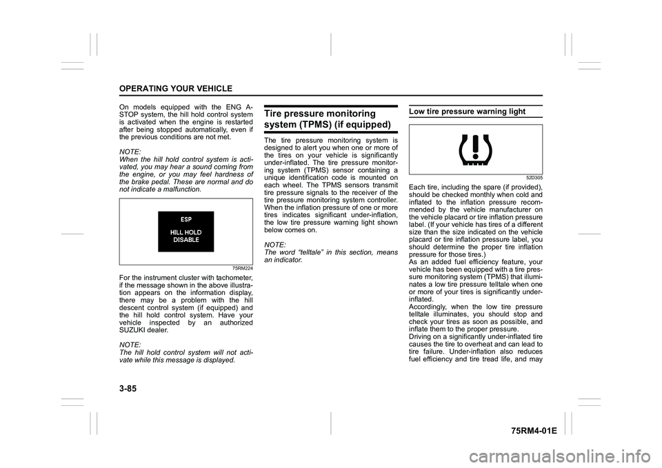
75RM224
For the instrument cluster with tachometer,
if the message shown in the above illustra-
tion appears on the information display,
there may be a problem with the hill
descent control system (if equipped) and
the hill hold control system. Have your
vehicle inspected by an authorized
SUZUKI dealer.
NOTE:
The hill hold control system will not acti-
vate while this message is displayed.
Tire pressure monitoring system (TPMS) (if equipped)The tire pressure monitoring system is
designed to alert you when one or more of
the tires on your vehicle is significantly
under-inflated. The tire pressure monitor-
ing system (TPMS) sensor containing a
unique identification code is mounted on
each wheel. The TPMS sensors transmit
tire pressure signals to the receiver of the
tire pressure monitoring system controller.
When the inflation pressure of one or more
tires indicates signif icant under-inflation,
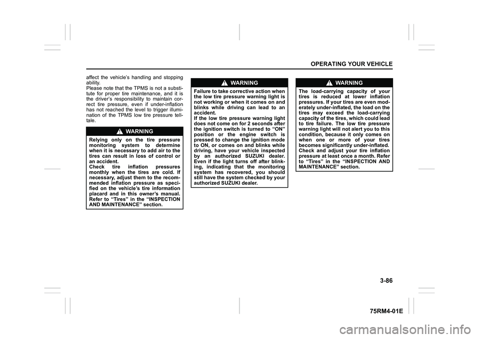
the low tire pressure warning light shown
below comes on.
NOTE:
The word “telltale” in this section, means
an indicator.
Low tire pressure warning light
52D305
Each tire, including the spare (if provided),
should be checked monthly when cold and
inflated to the inflation pressure recom-
mended by the vehicle manufacturer on
the vehicle placard or tire inflation pressure
label. (If your vehicle has tires of a different
size than the size indicated on the vehicle
placard or tire inflation pressure label, you
should determine the proper tire inflation
pressure for those tires.)
As an added fuel efficiency feature, your
vehicle has been equipped with a tire pres-
sure monitoring system (TPMS) that illumi-
nates a low tire pressure telltale when one
or more of your tires is significantly under-
inflated.
Accordingly, when the low tire pressure
telltale illuminates, you should stop and
check your tires as soon as possible, and
inflate them to the proper pressure.
Driving on a significantly under-inflated tire
causes the tire to overheat and can lead to
tire failure. Under-inf lation also reduces
fuel efficiency and tire tread life, and may
Page 239 of 505
3-86
OPERATING YOUR VEHICLE
75RM4-01E
affect the vehicle’s handling and stopping
ability.
Please note that the TPMS is not a substi-
tute for proper tire maintenance, and it is
the driver’s responsibility to maintain cor-
rect tire pressure, even if under-inflation
has not reached the level to trigger illumi-
nation of the TPMS low tire pressure tell-
tale.
WA R N I N G
Relying only on the tire pressure
monitoring system to determine
when it is necessary to add air to the
tires can result in loss of control or
an accident.
Check tire inflation pressures
monthly when the tires are cold. If
necessary, adjust them to the recom-
mended inflation pressure as speci-
fied on the vehicle’s tire information
placard and in this owner’s manual.
Refer to “Tires” in the “INSPECTION
AND MAINTENANCE” section.
WA R N I N G
Failure to take corrective action when
the low tire pressure warning light is
not working or when it comes on and
blinks while driving can lead to an
accident.
If the low tire pressure warning light
does not come on for 2 seconds after
the ignition switch is turned to “ON”
position or the engine switch is
pressed to change the ignition mode
to ON, or comes on and blinks while
driving, have your vehicle inspected
by an authorized SUZUKI dealer.
Even if the light tu rns off after blink-
ing, indicating that the monitoring
system has recovered, you should
still have the system checked by your
authorized SUZUKI dealer.
WA R N I N G
The load-carrying capacity of your
tires is reduced at lower inflation
pressures. If your tires are even mod-
erately under-inflated, the load on the
tires may exceed the load-carrying
capacity of the tires, which could lead
to tire failure. The low tire pressure
warning light will not alert you to this
condition, because it only comes on
when one or more of your tires
becomes significantly under-inflated.
Check and adjust your tire inflation
pressure at least once a month. Refer
to “Tires” in the “INSPECTION AND
MAINTENANCE” section.