Indicator SUZUKI IGNIS 2021 Service Manual
[x] Cancel search | Manufacturer: SUZUKI, Model Year: 2021, Model line: IGNIS, Model: SUZUKI IGNIS 2021Pages: 505, PDF Size: 8.36 MB
Page 135 of 505
2-112
BEFORE DRIVING
75RM4-01E
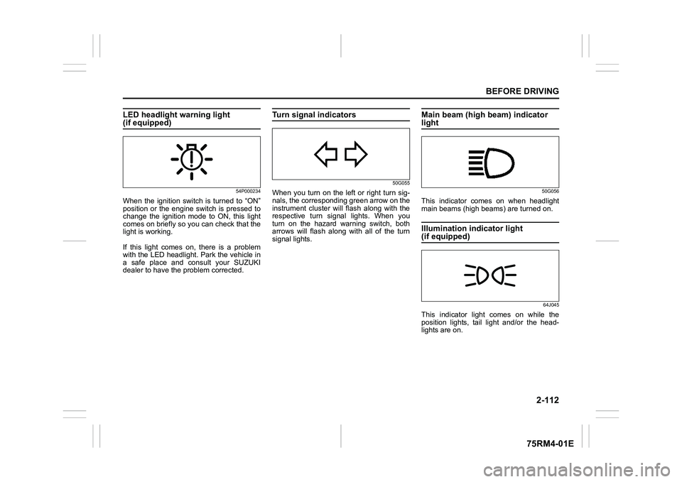
LED headlight warning light (if equipped)
54P000234
When the ignition switch is turned to “ON”
position or the engine switch is pressed to
change the ignition mode to ON, this light
comes on briefly so you can check that the
light is working.
If this light comes on, there is a problem
with the LED headlight. Park the vehicle in
a safe place and consult your SUZUKI
dealer to have the problem corrected.
Turn signal indicators
50G055
When you turn on the left or right turn sig-
nals, the corresponding green arrow on the
instrument cluster will flash along with the
respective turn signal lights. When you
turn on the hazard warning switch, both
arrows will flash along with all of the turn
signal lights.
Main beam (high beam) indicator light
50G056
This indicator comes on when headlight
main beams (high beams) are turned on.Illumination indicator light (if equipped)
64J045
This indicator light comes on while the
position lights, tail light and/or the head-
lights are on.
Page 137 of 505
2-114
BEFORE DRIVING
75RM4-01E
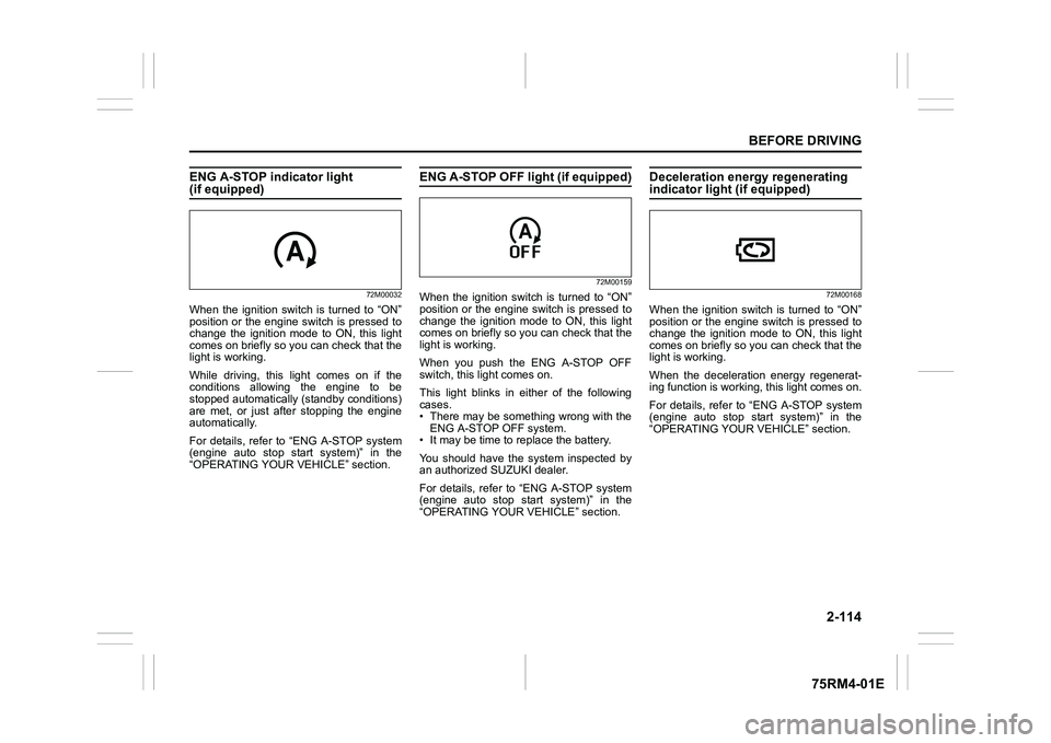
ENG A-STOP indicator light (if equipped)
72M00032
When the ignition switch is turned to “ON”
position or the engine switch is pressed to
change the ignition mode to ON, this light
comes on briefly so you can check that the
light is working.
While driving, this light comes on if the
conditions allowing the engine to be
stopped automatically (standby conditions)
are met, or just after stopping the engine
automatically.
For details, refer to “ENG A-STOP system
(engine auto stop start system)” in the
“OPERATING YOUR VEHICLE” section.
ENG A-STOP OFF light (if equipped)
72M00159
When the ignition switch is turned to “ON”
position or the engine switch is pressed to
change the ignition mode to ON, this light
comes on briefly so you can check that the
light is working.
When you push the ENG A-STOP OFF
switch, this light comes on.
This light blinks in either of the following
cases.
• There may be something wrong with theENG A-STOP OFF system.
• It may be time to replace the battery.
You should have the system inspected by
an authorized SUZUKI dealer.
For details, refer to “ENG A-STOP system
(engine auto stop start system)” in the
“OPERATING YOUR VEHICLE” section.
Deceleration energy regenerating indicator light (if equipped)
72M00168
When the ignition switch is turned to “ON”
position or the engine switch is pressed to
change the ignition mode to ON, this light
comes on briefly so you can check that the
light is working.
When the deceleration energy regenerat-
ing function is worki ng, this light comes on.
For details, refer to “ENG A-STOP system
(engine auto stop start system)” in the
“OPERATING YOUR VEHICLE” section.
Page 138 of 505
2-115BEFORE DRIVING
75RM4-01E
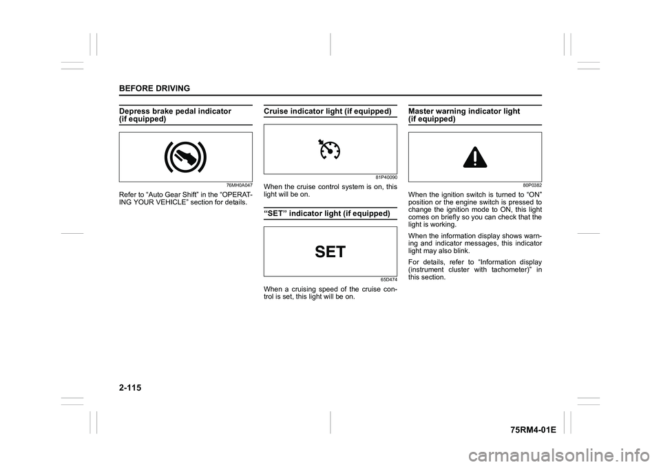
Depress brake pedal indicator (if equipped)
76MH0A047
Refer to “Auto Gear Shift” in the “OPERAT-
ING YOUR VEHICLE” section for details.
Cruise indicator light (if equipped)
81P40090
When the cruise control system is on, this
light will be on.“SET” indicator light (if equipped)
65D474
When a cruising speed of the cruise con-
trol is set, this light will be on.
Master warning indicator light (if equipped)
80P0382
When the ignition switch is turned to “ON”
position or the engine switch is pressed to
change the ignition mode to ON, this light
comes on briefly so you can check that the
light is working.
When the information display shows warn-
ing and indicator messages, this indicator
light may also blink.
For details, refer to “Information display
(instrument cluster with tachometer)” in
this section.
Page 142 of 505
2-119BEFORE DRIVING
75RM4-01E
NOTE:
• When the “To car” is functioning, thefront fog lights, rear fog lights and the
headlights (high beam) are not turned
on.
• Lighting time of the “To car” function can
be changed on the information display.
Refer to “Information display” in this sec-
tion.
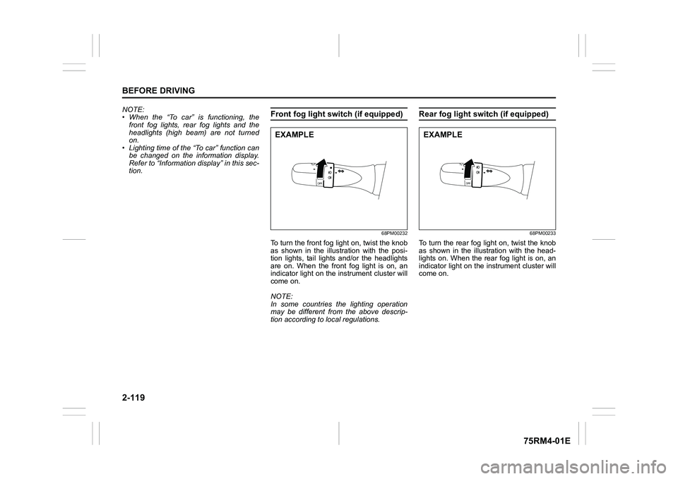
Front fog light swi tch (if equipped)
68PM00232
To turn the front fog light on, twist the knob
as shown in the illustration with the posi-
tion lights, tail lights and/or the headlights
are on. When the front fog light is on, an
indicator light on the in strument cluster will
come on.
NOTE:
In some countries the lighting operation
may be different from the above descrip-
tion according to local regulations.
Rear fog light switch (if equipped)
68PM00233
To turn the rear fog light on, twist the knob
as shown in the illustration with the head-
lights on. When the rear fog light is on, an
indicator light on the in strument cluster will
come on.
EXAMPLE
EXAMPLE
Page 147 of 505

2-124
BEFORE DRIVING
75RM4-01E
Turn signal operationWith the ignition switch in “ON” position or
the ignition mode ON, move the lever
upward or downward to activate the right
or left turn signals.
Normal turn signal
68PM00234
Move the lever all the way upward or
downward to signal. When the turn is com-
pleted, the signal will cancel and the lever
will return to its normal position.Lane change signal
68PM00235
Move the lever partway upward or down-
ward to turn right or left and hold the lever
in the moved position.
• The turn signal and its indicator flash
while the lever is held at the moved posi-
tion.
The turn signal and its indicator flash 3
times even if you return the lever immedi-
ately after moving it.
NOTE:
The turn signal and its indicator can be set
whether they flash 3 times after the turn
signal lever is returned via the information
display. Refer to “Information display” in
this section. NOTE:
You can customize the setting for the num-
ber of flashing times of the turn signal and
its indicator (1 to 4 times). Please ask an
authorized SUZUKI dealer for the customi-
zation.
EXAMPLE
EXAMPLE
Page 148 of 505
2-125BEFORE DRIVING
75RM4-01E
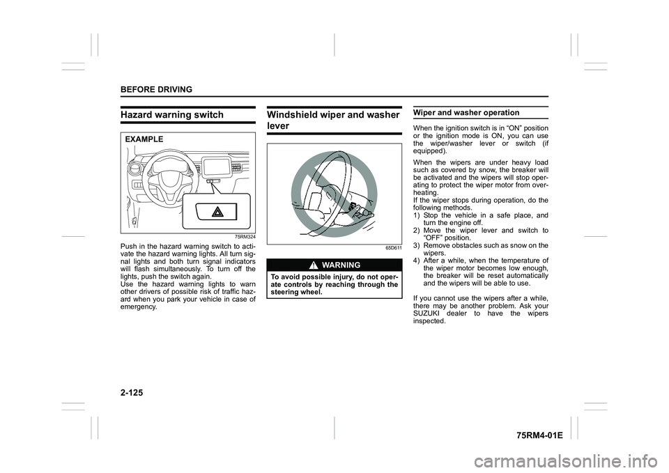
Hazard warning switch
75RM324
Push in the hazard warning switch to acti-
vate the hazard warning lights. All turn sig-
nal lights and both turn signal indicators
will flash simultaneously. To turn off the
lights, push the switch again.
Use the hazard warning lights to warn
other drivers of possible risk of traffic haz-
ard when you park your vehicle in case of
emergency.
Windshield wiper and washer lever
65D611
Wiper and washer operationWhen the ignition switch is in “ON” position
or the ignition mode is ON, you can use
the wiper/washer lever or switch (if
equipped).
When the wipers are under heavy load
such as covered by snow, the breaker will
be activated and the wipers will stop oper-
ating to protect the wiper motor from over-
heating.
If the wiper stops during operation, do the
following methods.
1) Stop the vehicle in a safe place, andturn the engine off.
2) Move the wiper lever and switch to “OFF” position.
3) Remove obstacles such as snow on the wipers.
4) After a while, when the temperature of
the wiper motor becomes low enough,
the breaker will be reset automatically
and the wipers will be able to use.
If you cannot use the wipers after a while,
there may be another problem. Ask your
SUZUKI dealer to have the wipers
inspected.
EXAMPLE
WA R N I N G
To avoid possible injury, do not oper-
ate controls by reaching through the
steering wheel.
Page 152 of 505
2-129BEFORE DRIVING
75RM4-01E
Heated rear window switch /
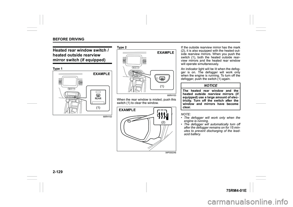
heated outside rearview mirror switch (if equipped)Ty p e 1
66RH102
Ty p e 2
66RH103
When the rear window is misted, push this
switch (1) to clear the window.
54P000246
If the outside rearview mirror has the mark
(2), it is also equipped with the heated out-
side rearview mirrors. When you push the
switch (1), both the heated outside rear-
view mirrors and the heated rear window
will operate simultaneously.
An indicator light will be lit when the defog-
ger is on. The defogger will work only
when the engine is running. To turn off the
defogger, push the switch (1) again.
NOTE:
• The defogger will work only when the engine is running.
• The defogger will automatically turn off
after the defogger remains on for 15 min-
utes to prevent discharging of the lead-
acid battery.
(1)EXAMPLE
(1)EXAMPLE
(2)
EXAMPLE
NOTICE
The heated rear window and the
heated outside rearview mirrors (if
equipped) use a large amount of elec-
tricity. Turn off the switch after the
window and mirrors have become
clear.
Page 153 of 505
OPERATING YOUR VEHICLE
3
75RM4-01E
60G408
OPERATING YOUR VEHICLEExhaust gas warning .......................................................... 3-1
Daily inspection checklist .................................... .............. 3-1
Engine oil consumption ........................................ ............. 3-2
Ignition switch
(vehicle without keyless push s tart system) ....................3-3
Engine switch
(vehicle with keyless push sta rt system) .......................... 3-5
Keyless push start system (if equipped) .......................... 3-6
Parking brake lever ........................................... .................. 3-10
Pedal ......................................................... ............................ 3-12
Starting engine
(vehicle without keyless push s tart system) ....................3-13
Starting engine
(vehicle with keyless push sta rt system) .......................... 3-14
Using transaxle ... ....................... ......................................... 3-17
Gearshift indicator (if equipped) ............................. ........... 3-33
ENG A-STOP system
(engine auto stop start system) (if equipped) ................. .3-35
Cruise control (if equipped) ............................................... 3-48
Speed limiter (if equipped) ................................... .............. 3-51
Dual camera brake support (if equipped) ......................... 3-53
Emergency stop signal (ESS) (if equipped) ......................3-71
Rearview camera (if equipped) ................................. ......... 3-72
Braking ....................................................... .......................... 3-75
Electronic stabi lity program (ESP
®) (if equipped) ........... 3-78
Tire pressure monito ring system (TPMS) (i f equipped) .. 3-85
Page 161 of 505
3-8
OPERATING YOUR VEHICLE
75RM4-01E
NOTE:
• CVT – If the gearshift lever is in anyposition other than “P”, or if the knob but-
ton is pushed when the gearshift lever is
in “P” position the ignition mode cannot
be returned to LOCK (OFF).
• When selecting the ignition modes, the information display in the instrument
cluster shows certain messages. Refer
to “Information display” in the “BEFORE
DRIVING” section for details.
If the master warning indicator light
blinks and the ignition modes cannot
be selected
Your keyless push start system remote
controller may not be sensed as being
within the interior wo rkable area (refer to
the related explanation in this section). Try
again after checking that you have the
remote controller with you. If the ignition
modes still cannot be selected, the battery
of the remote controller may be dis-
charged. To select an ignition mode, you
must then use the following method:
58MST0302
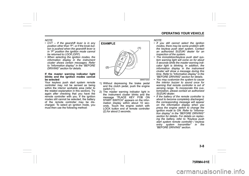
1) Without depressing the brake pedal
and the clutch pedal, push the engine
switch (1).
2) The master warning indicator light in the instrument cluster blinks and the
message “PLACE KEY FOB ON
START SWITCH” appears on the infor-
mation display within about 10 sec-
onds. Touch the engine switch with
LOCK button end of remote controller
(2) for about 2 seconds. NOTE:
• If you still cannot
select the ignition
modes, there may be some problem with
the keyless push start system. Contact
an authorized SUZUKI dealer for an
inspection of the system.
• The immobilizer/keyless push start sys- tem warning light will come on for about
5 seconds while the master warning indi-
cator light is blinking. In addition, the
information display in the instrument
cluster will show a message during this
time. Refer to “Informa tion display” in the
“BEFORE DRIVING” section for details.
• You may customize the system to cause
the interior buzzer to sound once for
warning that remote controller is out of
sensing range. To incorporate this cus-
tomization, please contact an authorized
SUZUKI dealer.
• If the battery of the remote controller is about to become completely discharged,
the corresponding message will appear
on the information display when you
press the engine switch to change the
ignition mode to ON. Refer to “Informa-
tion display” in the “BEFORE DRIVING”
section for details. For details on replac-
ing the battery, refer to “Keyless push
start system remote controller / keyless
entry system transmitter” in the
“BEFORE DRIVING” section.
(1)
(2)
EXAMPLE
Page 162 of 505
3-9OPERATING YOUR VEHICLE
75RM4-01E
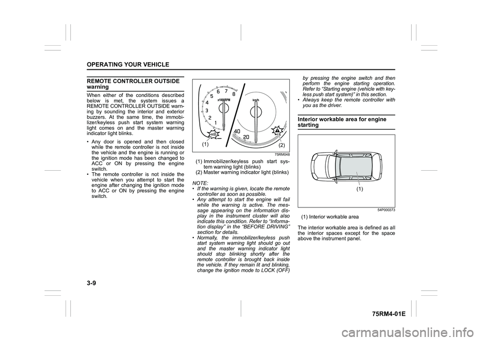
REMOTE CONTROLLER OUTSIDE warningWhen either of the conditions described
below is met, the system issues a
REMOTE CONTROLLER OUTSIDE warn-
ing by sounding the interior and exterior
buzzers. At the same time, the immobi-
lizer/keyless push start system warning
light comes on and the master warning
indicator light blinks.
• Any door is opened and then closedwhile the remote controller is not inside
the vehicle and the engine is running or
the ignition mode has been changed to
ACC or ON by pressing the engine
switch.
• The remote controller is not inside the vehicle when you attempt to start the
engine after changing the ignition mode
to ACC or ON by pressing the engine
switch.
75RM048
(1) Immobilizer/keyless push start sys- tem warning light (blinks)
(2) Master warning indi cator light (blinks)
NOTE:
• If the warning is given, locate the remote controller as soon as possible.
• Any attempt to start the engine will fail
while the warning is active. The mes-
sage appearing on the information dis-
play in the instrument cluster will also
indicate this condition. Refer to “Informa-
tion display” in the “BEFORE DRIVING”
section for details.• Normally, the immobilizer/keyless push start system warning light should go out
and the master warning indicator light
should stop blinking shortly after the
remote controller is brought back inside
the vehicle. If they remain lit and blinking,
change the ignition mode to LOCK (OFF) by pressing the engine switch and then
perform the engine starting operation.
Refer to “Starting engine (vehicle with key-
less push start system)” in this section.
• Always keep the remote controller with
you as the driver.Interior workable area for engine starting
54P000373
(1) Interior workable area
The interior workable area is defined as all
the interior spaces except for the space
above the instrument panel.
(2)
(1)
(1)