Indicator SUZUKI IGNIS 2021 Owners Manual
[x] Cancel search | Manufacturer: SUZUKI, Model Year: 2021, Model line: IGNIS, Model: SUZUKI IGNIS 2021Pages: 505, PDF Size: 8.36 MB
Page 17 of 505
ILLUSTRATED TABLE OF CONTENTS
75RM4-01E
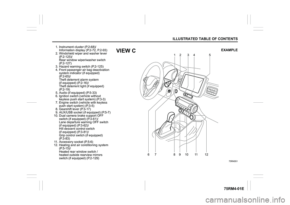
1. Instrument cluster (P.2-68)/Information display (P.2-72, P.2-93)
2. Windshield wiper and washer lever
(P.2-125)/
Rear window wiper/washer switch
(P.2-127)
3. Hazard warning switch (P.2-125)
4. Front passenger air bag deactivation system indicator (if equipped)
(P.2-65)/
Theft deterren t alarm system
(if equipped) (P.2-16)/
Theft deterrent light (if equipped)
(P.2-19)
5. Audio (if equipped) (P.5-33)
6. Ignition switch (vehicle without keyless push start system) (P.3-3)
7. Engine switch (v ehicle with keyless
push start system) (P.3-5)
8. Gearshift lever (P.3-17)
9. AUX/USB socket (if equipped) (P.5-7)
10. Dual camera brake support OFF switch (if equipped) (P.3-61)/
Lane departure warning OFF switch
(if equipped) (P.3-62)/
Hill descent control switch
(if equipped) (P.3-81)/
Grip control switch (if equipped)
(P.3-83)
11. Accessory socket (P.5-6)
12. Heating and air co nditioning system
(P.5-15)/
Heated rear window switch /
heated outside rearview mirrors
switch (if equipped) (P.2-129)
75RM261
6
79
10 11
812 12
5
34
EXAMPLE
VIEW C
Page 23 of 505
BEFORE DRIVING
2
75RM4-01E
60G404
Keys ......................................................................................2-1
Door locks .................................................... ........................2-2
Keyless push start system remote controller /
Keyless entry system transmitte r (if equipped) ................2-7
Theft deterrent alarm system (if equipped) .................... ...2-16
Theft deterrent light (if equipped) ........................... ...........2-19
Windows ....................................................... ........................2-20
Mirrors ....................................................... ...........................2-23
Front seats ................................................... ........................2-27
Rear seats .................................................... .........................2-29
BEFORE DRIVINGSeat belts and child restraint systems ........................ ...... 2-33
Child restraint system f or countries applied for
UN Regulation No.16 ........................................... ................ 2-43
Supplemental restraint system (air bags) ...................... ... 2-54
Instrument cluster ............................................ ................... 2-68
Speedometer ................................................... .................... 2-69
Tachometer (if equipped) ...................................... ............. 2-69
Fuel gauge .................................................... ....................... 2-70
Brightness control ............................................ .................. 2-70
Information display
(instrument clus ter with tachometer) .......................... ...... 2-72
Information display
(instrument clus ter without tachometer) ....................... ... 2-93
Warning and indicator lights .................................. .......... 2-101
Lighting control lever ........................................ ............... 2-116
Headlight leveling switch (if equipped) ....................... .... 2-123
Turn signal control lever ..................................... ............. 2-123
Hazard warning switch ......................................... ............ 2-125
Windshield wiper and washer lever ............................. ... 2-125
Tilt steering lock lever ... ................................................... 2-128
Horn .......................................................... .......................... 2-128
Heated rear window switch /
heated outside rearview mirror switch (if equipped) ..... 2-129
Page 25 of 505
2-2
BEFORE DRIVING
75RM4-01E
For vehicles with a keyless push start
system
If this light blinks, change the ignition mode
to LOCK (OFF), and then change it back to
ON. Also refer to “If the master warning
indicator light blinks and the engine cannot
be started” in “Starting engine (vehicle with
keyless push start system)” in the “OPER-
ATING YOUR VEHICLE” section.
If the light still blinks after the ignition mode
is changed back to ON, there may be
something wrong with your key or with the
immobilizer system. Ask your SUZUKI
dealer to have the system inspected.
The immobilizer/keyless push start system
warning light may also blinks if the remote
controller is not in the vehicle when you
close the door or attempt to start the
engine.
NOTE:
• If you lose your immobilizer ignition key or remote controller, ask your SUZUKI
dealer as soon as possible to deactivate
the lost one, and to make a new key or
remote controller.
• If you own other v ehicles with immobi-
lizer keys, keep those keys away from
the ignition switch or the engine switch
when using your SUZUKI vehicle. Other-
wise, or the engine may not be started
because they may interfere with your
SUZUKI vehicle’s immobilizer system. • If you attach any metal objects to the
immobilizer key or remote controller, it
may not start the engine.
Ignition key reminderA buzzer sounds intermittently to remind
you to remove the ignition key if it is in the
ignition switch when the driver’s door is
opened.
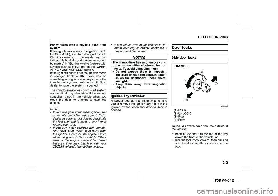
Door locksSide door locks
60B008
(1) LOCK
(2) UNLOCK
(3) Rear
(4) Front
To lock a driver’s door from the outside of
the vehicle:
• Insert a key and turn the top of the key toward the front o f the vehicle, or
• Turn the lock knob forward, then pull and
hold the door handle as you close the
door.
NOTICE
The immobilizer key and remote con-
troller are sensitive electronic instru-
ments. To avoid damaging them:
• Do not expose them to impacts,moisture or high temperature such
as on the dashboard under direct
sunlight.
• Keep them away from magnetic
objects.
(2)
(1) (3)
(4)
EXAMPLE
Page 34 of 505
2-11BEFORE DRIVING
75RM4-01E
57L21016
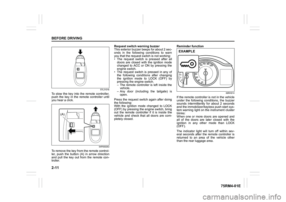
To stow the key into the remote controller,
push the key in the remote controller until
you hear a click.
54P000263
To remove the key from the remote control-
ler, push the button (A) in arrow direction
and pull the key out from the remote con-
troller.Request switch warning buzzer
This exterior buzzer beeps for about 2 sec-
onds in the following conditions to warn
you that the request s
witch is not working:
• The request switch is pressed after all doors are closed with the ignition mode
changed to ACC or ON by pressing the
engine switch.
• The request switch is pressed in any of
the following conditions after changing
the ignition mode to LOCK (OFF) by
pressing the engine switch.
– The remote controller is left inside thevehicle.
– Any door (including the tailgate) is
open.
Press the request switch again after doing
the following:
With the ignition mode changed to LOCK
(OFF) by pressing the engine switch, bring
out the remote controller if it is inside the
vehicle and check that all doors are com-
pletely closed. Reminder function
66RH014
If the remote controller is not in the vehicle
under the following conditions, the buzzer
sounds intermittently for about 2 seconds
and the immobilizer/keyless push start sys-
tem warning light on the instrument cluster
blinks:
When one or more doors are opened and
all of the doors are later closed with the
ignition in any other mode than LOCK
(OFF).
The indicator light will turn off within sev-
eral seconds after the remote controller is
returned to an area of the vehicle other
than the rear luggage area.
(A)
EXAMPLE
Page 51 of 505
2-28
BEFORE DRIVING
75RM4-01E
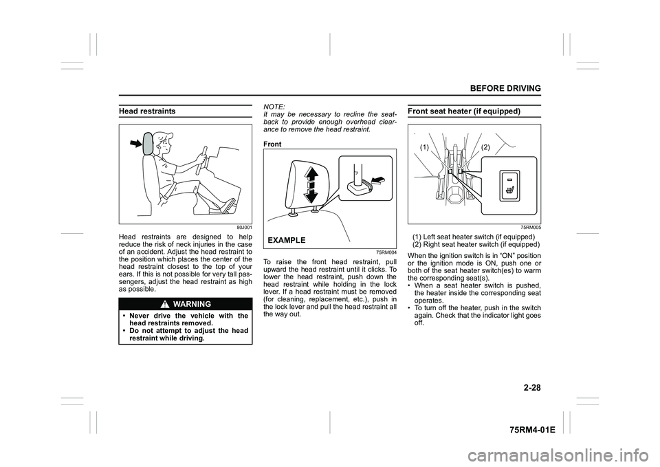
Head restraints
80J001
Head restraints are designed to help
reduce the risk of neck injuries in the case
of an accident. Adjust the head restraint to
the position which places the center of the
head restraint closest to the top of your
ears. If this is not possible for very tall pas-
sengers, adjust the head restraint as high
as possible.NOTE:
It may be necessary to recline the seat-
back to provide enough overhead clear-
ance to remove the head restraint.
Front
75RM004
To raise the front head restraint, pull
upward the head restraint until it clicks. To
lower the head restraint, push down the
head restraint while holding in the lock
lever. If a head restraint must be removed
(for cleaning, replacement, etc.), push in
the lock lever and pull the head restraint all
the way out.
Front seat heater (if equipped)
75RM005
(1) Left seat heater s
witch (if equipped)
(2) Right seat heater switch (if equipped)
When the ignition switch is in “ON” position
or the ignition mode is ON, push one or
both of the seat heater switch(es) to warm
the corresponding seat(s).
• When a seat heater switch is pushed, the heater inside the corresponding seat
operates.
• To turn off the heater, push in the switch
again. Check that the indicator light goes
off.
WA R N I N G
• Never drive the vehicle with thehead restraints removed.
• Do not attempt to adjust the head restraint while driving.
EXAMPLE
(1)
(2)
Page 88 of 505
2-65BEFORE DRIVING
75RM4-01E
Your vehicle is equipped with a diagnostic
module which records information about
the air bag system if the air bags deploy in
a crash. The module records information
about overall system status, and which
sensors activated the deployment.
Servicing the air bag system
If the air bags inflate, have the air bags
and related components replaced by an
authorized SUZUKI dealer as soon as pos-
sible.
If your vehicle ever gets in deep water and
the driver’s floor is submerged, the air bag
controller could be damaged. If this hap-
pens, ask your SUZUKI dealer to check
the air bag system as soon as possible.
Special procedures are required for servic-
ing or replacing an air bag. For that rea-
son, only an authorized SUZUKI dealer
should be allowed to service or replace
your air bags. Remind anyone who ser-
vices your SUZUKI vehicle that it has air
bags.
Service on or around air bag components
or wiring must be performed only by an
authorized SUZUKI dealer. Improper ser-
vice could result in unintended air bag
deployment or could render the air bag
inoperative. Either of these two conditions
may result in severe injury. To prevent damage or unintended inflation
of the air bag system, check that the lead-
acid battery is disconnected and the igni-
tion switch has been in “LOCK” position or
the ignition mode has been LOCK (OFF)
for at least 90 seconds before performing
any electrical service work on your
SUZUKI vehicle. Do not touch air bag sys-
tem components or wires. The wires are
wrapped with yellow tape or yellow tubing,
and the couplers are yellow for easy identi-
fication.
Scrapping a vehicle that has an uninflated
air bag can be hazardous. Ask your dealer,
body repair shop or scrap yard for help
with disposal.
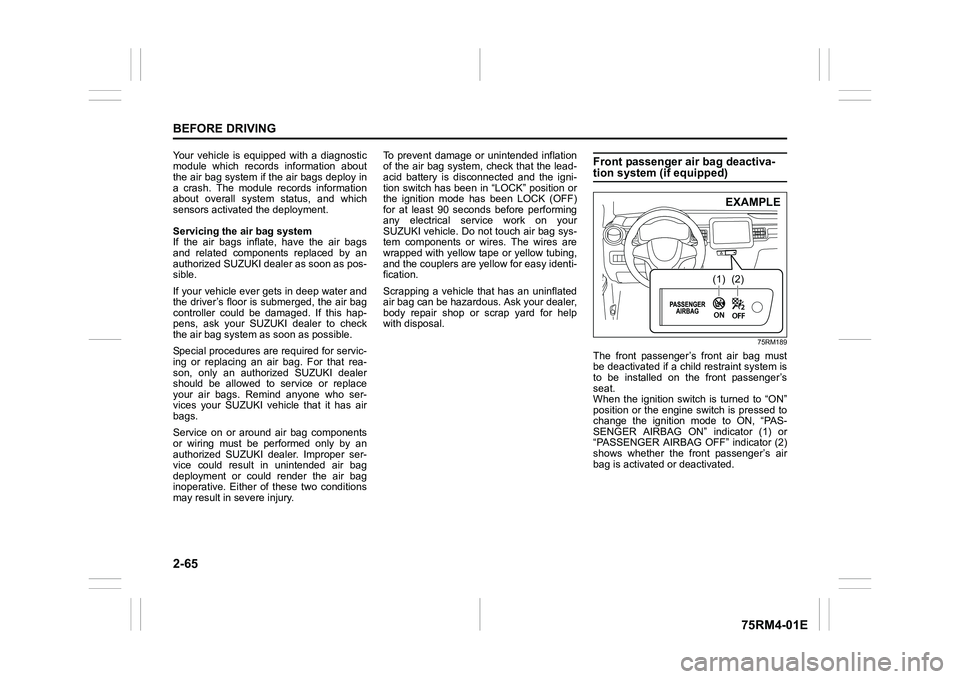
Front passenger air bag deactiva-tion system (if equipped)
75RM189
The front passenger’s front air bag must
be deactivated if a child restraint system is
to be installed on the front passenger’s
seat.
When the ignition switch is turned to “ON”
position or the engine switch is pressed to
change the ignition mode to ON, “PAS-
SENGER AIRBAG ON” indicator (1) or
“PASSENGER AIRBAG OFF” indicator (2)
shows whether the front passenger’s air
bag is activated or deactivated.
(1)
(2)EXAMPLE
Page 89 of 505
2-66
BEFORE DRIVING
75RM4-01E
When the front passenger’s air bag is acti-
vated, both “PASSENGER AIRBAG ON”
indicator (1) and “PASSENGER AIRBAG
OFF” indicator (2) come on for a few sec-
onds and then go out.
After that, only “PASSENGER AIRBAG
ON” indicator (1) comes on for about 1
minute and then goes out.
When the front passenger’s air bag is
deactivated, both “PASSENGER AIRBAG
ON” indicator (1) and “PASSENGER AIR-
BAG OFF” indicator (2 ) come on for a few
seconds and t hen go out.
After that, only “PASSENGER AIRBAG
OFF” indicator (2) comes on.
When you activate or deactivate the front
passenger’s air bag, check which indicator
is on before starting the engine.
Side air bags, side curtain air bags and
seat belt pretensioners are not connected
to the air bag deactivation system. Even if
the front passenger’s air bag is deacti-
vated, side air bags, side curtain air bags
and seat belt pretensioners are still acti-
vated.
58MS030
According to accident s tatistics, children
are safer when properly restrained in rear
seating positions than front seating posi-
tions. Whenever possible, SUZUKI recom-
mends that child restraint systems be
installed on the rear seat.
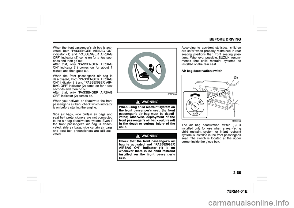
Air bag deactivation switch
75RM165
The air bag deactivation switch (3) is
installed only for use when a rear-facing
child restraint system or infant restraint
system is installed in the front passenger’s
seat. The switch is located at the upper
corner inside the glove box.
WA R N I N G
When using child restraint system on
the front passenger’s seat, the front
passenger’s air bag must be deacti-
vated; otherwise deployment of the
front passenger’s air bag could result
in the death or serious injury of the
child.
WA R N I N G
Check that the front passenger’s air
bag is activated and “PASSENGER
AIRBAG ON” indicator (1) is on
whenever there is no child restraint
installed on the front passenger’s
seat.
(3)
Page 90 of 505
2-67BEFORE DRIVING
75RM4-01E
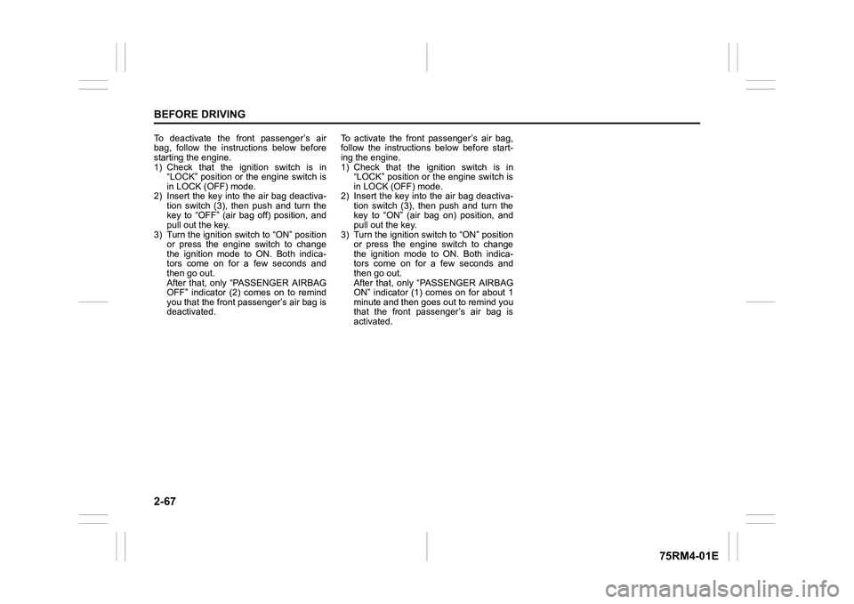
To deactivate the front passenger’s air
bag, follow the instructions below before
starting the engine.
1) Check that the ignition switch is in“LOCK” position or the engine switch is
in LOCK (OFF) mode.
2) Insert the key into the air bag deactiva- tion switch (3), then push and turn the
key to “OFF” (air bag off) position, and
pull out the key.
3) Turn the ignition switch to “ON” position or press the engine switch to change
the ignition mode to ON. Both indica-
tors come on for a few seconds and
then go out.
After that, only “PASSENGER AIRBAG
OFF” indicator (2) comes on to remind
you that the front pa ssenger’s air bag is
deactivated. To activate the front passenger’s air bag,
follow the instructions below before start-
ing the engine.
1) Check that the ignition switch is in
“LOCK” position or the engine switch is
in LOCK (OFF) mode.
2) Insert the key into the air bag deactiva- tion switch (3), then push and turn the
key to “ON” (air bag on) position, and
pull out the key.
3) Turn the ignition switch to “ON” position or press the engine switch to change
the ignition mode to ON. Both indica-
tors come on for a few seconds and
then go out.
After that, only “PASSENGER AIRBAG
ON” indicator (1) co mes on for about 1
minute and then goes out to remind you
that the front passenger’s air bag is
activated.
Page 91 of 505
2-68
BEFORE DRIVING
75RM4-01E
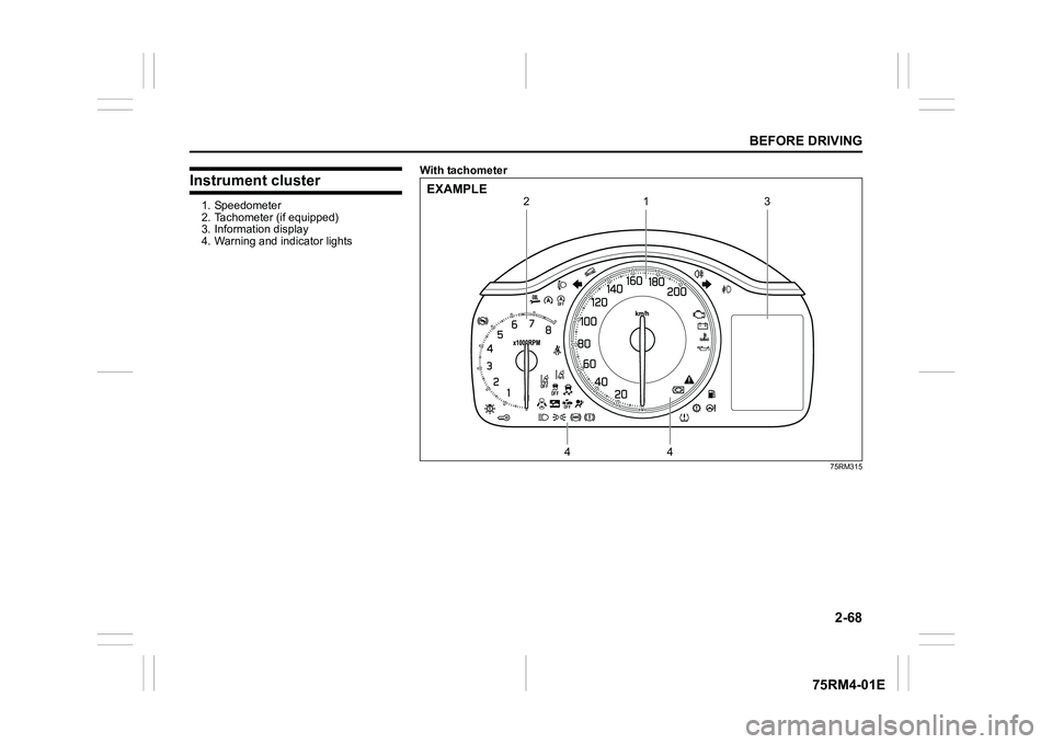
Instrument cluster1. Speedometer
2. Tachometer (if equipped)
3. Information display
4. Warning and indicator lightsWith tachometer
75RM315
1
4
4
2
3
EXAMPLE
Page 93 of 505
2-70
BEFORE DRIVING
75RM4-01E
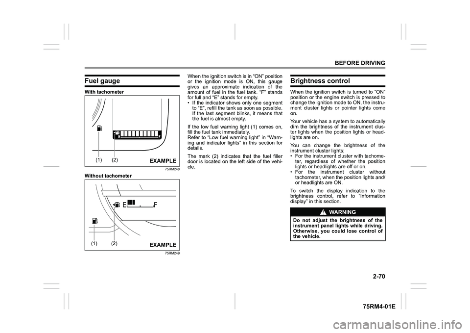
Fuel gaugeWith tachometer
75RM248
Without tachometer
75RM249
When the ignition switch is in “ON” position
or the ignition mode is ON, this gauge
gives an approximate indication of the
amount of fuel in the fuel tank. “F” stands
for full and “E” stands for empty.
• If the indicator shows only one segmentto “E”, refill the tank as soon as possible.
If the last segment blinks, it means that
the fuel is almost empty.
If the low fuel warning light (1) comes on,
fill the fuel tank immediately.
Refer to “Low fuel warning light” in “Warn-
ing and indicator lights” in this section for
details.
The mark (2) indicates that the fuel filler
door is located on the left side of the vehi-
cle.
Brightness controlWhen the ignition switch is turned to “ON”
position or the engine switch is pressed to
change the ignition mode to ON, the instru-
ment cluster lights or pointer lights come
on.
Your vehicle has a system to automatically
dim the brightness of the instrument clus-
ter lights when the position lights or head-
lights are on.
You can change the brightness of the
instrument cluster lights;
• For the instrument c luster with tachome-
ter, regardless of whether the position
lights or headlights are off or on.
• For the instrum ent cluster without
tachometer, when the position lights and/
or headlights are ON.
To switch the display indication to the
brightness control, re fer to “Information
display” in this section.
(1)
(2)
EXAMPLE
(1)
(2)
EXAMPLE
WA R N I N G
Do not adjust the brightness of the
instrument panel lights while driving.
Otherwise, you could lose control of
the vehicle.