cvt SUZUKI IGNIS 2021 Owners Manual
[x] Cancel search | Manufacturer: SUZUKI, Model Year: 2021, Model line: IGNIS, Model: SUZUKI IGNIS 2021Pages: 505, PDF Size: 8.36 MB
Page 1 of 505
Classification: API SG, SH, SJ, SL, SM or SN
Viscosity: SAE 0W-20, 5W-30, 10W-30, 10W-40,
15W-40, 20W-40
(K12M engine models)
(K12C engine models)
22.0 mmENGLISH
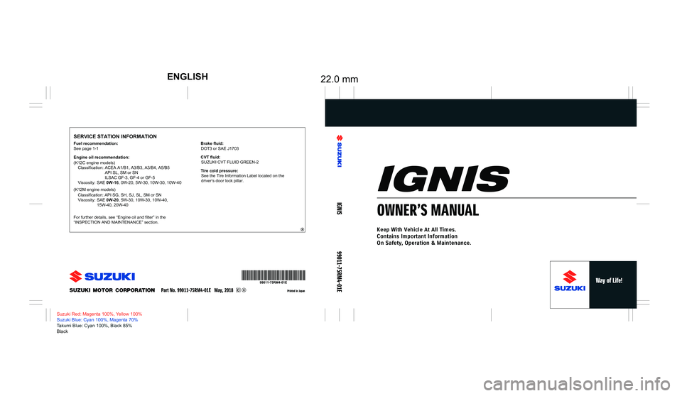
SERVICE STATION INFORMATION
Printed in Japan
Suzuki Red: Magenta 100%, Yellow 100%
Suzuki Blue: Cyan 100%, Magenta 70%
Takumi Blue: Cyan 100%, Black 85%
Black
IGNIS
99011-75RM4-01E
OWNER’S MANUAL
Keep With Vehicle At All Times.
Contains Important Information
On Safety, Operation & Maintenance.
See page 1-1
Fuel recommendation:
Engine oil recommendation:
Classification: ACEA A1/B1, A3/B3, A3/B4, A5/B5
API SL, SM or SN
ILSAC GF-3, GF-4 or GF-5
Viscosity: SAE 0W-16, 0W-20, 5W-30, 10W-30, 10W-40
For further details, see “Engine oil and filter” in the
“INSPECTION AND MAINTENANCE” section.
Part No. 99011-75RM4-01E May, 2018
Brake fluid: DOT3 or SAE J1703
Tire cold pressure: See the Tire Information Label located on the
driver’s door lock pillar.
CVT fluid:
SUZUKI CVT FLUID GREEN-2
Page 9 of 505
75RM4-01E
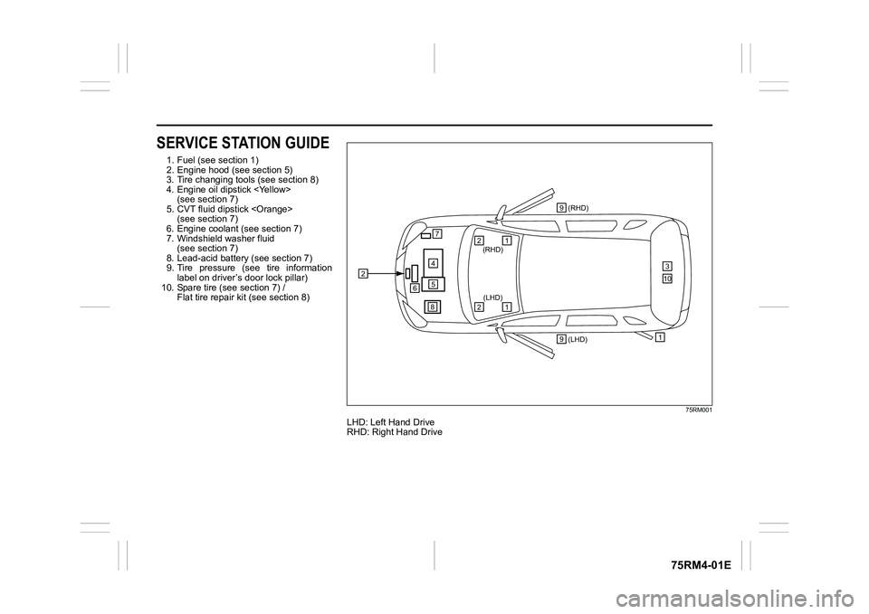
SERVICE STATION GUIDE1. Fuel (see section 1)
2. Engine hood (see section 5)
3. Tire changing tools (see section 8)
4. Engine oil dipstick
5. CVT fluid dipstick
6. Engine coolant (see section 7)
7. Windshield washer fluid (see section 7)
8. Lead-acid battery (see section 7)
9. Tire pressure (see tire information label on driver’s door lock pillar)
10. Spare tire (see section 7) / Flat tire repair kit (see section 8)
75RM001
LHD: Left Hand Drive
RHD: Right Hand Drive
2
457
6
(LHD) 1(RHD)
3
1
(RHD)
2
1
(LHD)
2
8 9
9
10
Page 96 of 505
2-73BEFORE DRIVING
75RM4-01E
75RM183
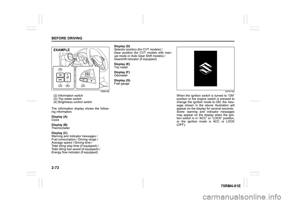
(2) Information switch
(3) Trip meter switch
(4) Brightness control switch
The information display shows the follow-
ing information.
Display (A)
Clock
Display (B)
Thermometer
Display (C)
Warning and indicator messages /
Fuel consumption / Driving range /
Average speed / Driving time /
Total idling stop time (if equipped) /
Total idling fuel saved (if equipped) /
Energy flow indicator (if equipped) Display (D)
Selector position (for CVT models) /
Gear position (for CVT models with man-
ual mode or Auto Gear Shift models) /
Gearshift indicator (if equipped)
Display (E)
Trip meter
Display (F)
Odometer
Display (G)
Fuel gauge
81P31150
When the ignition switch is turned to “ON”
position or the engine switch is pressed to
change the ignition mode to ON, the mes-
sage shown in the above illustration will
appear on the display
for several seconds.
Some warning and indicator messages
may appear on the display when the igni-
tion switch is in “ACC” or “LOCK” position,
or the ignition mode is ACC or LOCK
(OFF).
(4)
(2)(3)
(2)
EXAMPLE
Page 100 of 505
2-77BEFORE DRIVING
75RM4-01E
Total idling fuel saved (if equipped)
The display shows the total amount (in mil-
liliters) of fuel conservation by ENG A-
STOP system since the indication was
reset.
• To reset the total idling fuel saved tozero, push and hold the information
switch (2) for a while when the display
shows the total idling fuel saved.
NOTE:
When you reconnect the negative (–) ter-
minal to the lead-acid battery, the value of
the total idling fuel saved will be reset.
Energy flow indicator (if equipped)
Refer to “ENG A-ST OP system (engine
auto stop start system)” in the “OPERAT-
ING YOUR VEHICLE” section.
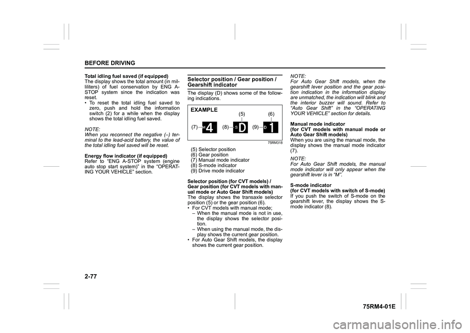
Selector position / Gear position / Gearshift indicatorThe display (D) shows some of the follow-
ing indications.
75RM318
(5) Selector position
(6) Gear position
(7) Manual mode indicator
(8) S-mode indicator
(9) Drive mode indicator
Selector position (for CVT models) /
Gear position (for CVT models with man-
ual mode or Auto Gear Shift models)
The display shows th e transaxle selector
position (5) or the gear position (6).
• For CVT models with manual mode; – When the manual mode is not in use,
the display shows the selector posi-
tion.
– When using the manual mode, the dis-
play shows the current gear position.
• For Auto Gear Shift models, the display shows the current gear position. NOTE:
For Auto Gear Shif
t models, when the
gearshift lever position and the gear posi-
tion indication in the information display
are unmatched, the indication will blink and
the interior buzzer will sound. Refer to
“Auto Gear Shift” in the “OPERATING
YOUR VEHICLE” section for details.
Manual mode indicator
(for CVT models with manual mode or
Auto Gear Shift models)
When you are using the manual mode, the
display shows the manual mode indicator
(7).
NOTE:
For Auto Gear Shift models, the manual
mode indicator will only appear when the
gearshift lever is in “M”.
S-mode indicator
(for CVT models with switch of S-mode)
If you push the switch of S-mode on the
gearshift lever, the display shows the S-
mode indicator (8).(7)
(8)
(5)
(9)
(6)
EXAMPLE
Page 108 of 505
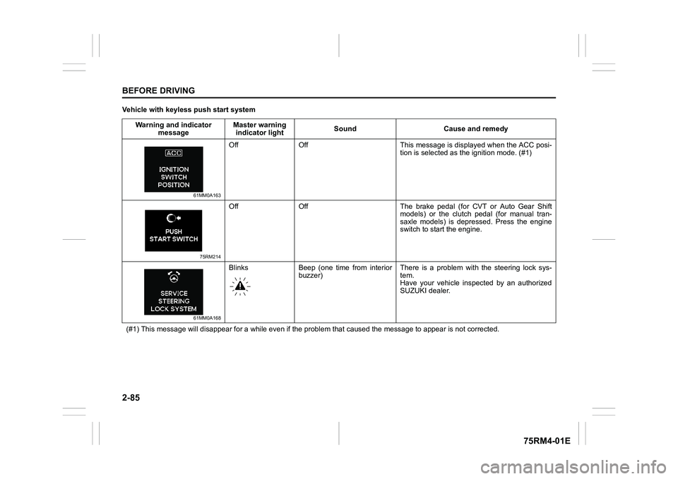
2-85BEFORE DRIVING
75RM4-01E
Vehicle with keyless push start systemWarning and indicator message Master warning
indicator light Sound Cause and remedy
61MM0A163
Off Off This message is displayed when the ACC posi-
tion is selected as the ignition mode. (#1)
75RM214
Off Off The brake pedal (for CVT or Auto Gear Shift
models) or the clutch pedal (for manual tran-
saxle models) is depressed. Press the engine
switch to start the engine.
61MM0A168
Blinks Beep (one time from interiorbuzzer) There is a problem with the steering lock sys-
tem.
Have your vehicle inspected by an authorized
SUZUKI dealer.
(#1) This message will disappear for a while even if the proble m that caused the message to appear is not corrected.
Page 110 of 505
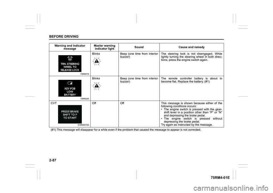
2-87BEFORE DRIVING
75RM4-01E
75RM219
Blinks Beep (one time from interiorbuzzer) The steering lock is not disengaged. While
lightly turning the steering wheel in both direc-
tions, press the engine switch again.
75RM220
Blinks Beep (one time from interior
buzzer) The remote controller battery is about to
become flat. Repla
ce the battery. (#1)
CVT
61MM0A165
Off Off This message is shown because either of the following conditions occurs:
• The engine switch is pressed with the gear-shift lever in a position other than “P” or “N”
and depressing the brake pedal.
• The engine switch is pressed without depressing the brake pedal.
Try again as instruct ed by the message.
(#1) This message will disappear for a while even if the proble m that caused the message to appear is not corrected.
Warning and indicator
message Master warning
indicator light Sound Cause and remedy
Page 111 of 505
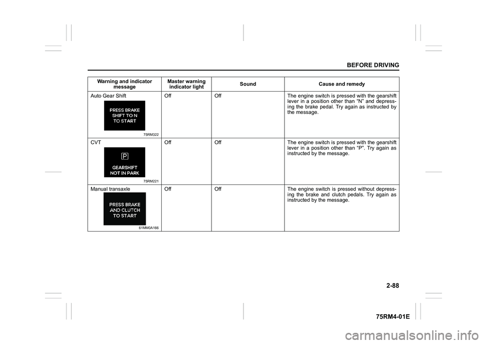
2-88
BEFORE DRIVING
75RM4-01E
Auto Gear Shift
75RM322
Off Off The engine switch is pressed with the gearshiftlever in a position other than “N” and depress-
ing the brake pedal. Try again as instructed by
the message.
CVT
75RM221
Off Off The engine switch is pressed with the gearshift lever in a position other than “P”. Try again as
instructed by the message.
Manual transaxle
61MM0A166
Off Off The engine switch is pressed without depress- ing the brake and clutch pedals. Try again as
instructed by the message.
Warning and indicator
message Master warning
indicator light Sound Cause and remedy
Page 112 of 505
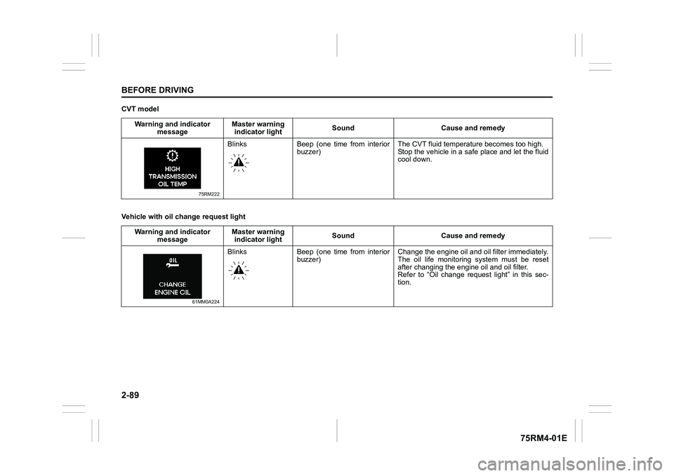
2-89BEFORE DRIVING
75RM4-01E
CVT model
Vehicle with oil change request lightWarning and indicator
message Master warning
indicator light Sound Cause and remedy
75RM222
Blinks Beep (one time from interior
buzzer) The CVT fluid temper
ature becomes too high.
Stop the vehicle in a safe place and let the fluid
cool down.
Warning and indicator message Master warning
indicator light Sound Cause and remedy
61MM0A224
Blinks Beep (one time from interior
buzzer) Change the engine oil and oil filter immediately.
The oil life monitoring system must be reset
after changing the engine oil and oil filter.
Refer to “Oil change request light” in this sec-
tion.
Page 116 of 505
2-93BEFORE DRIVING
75RM4-01E
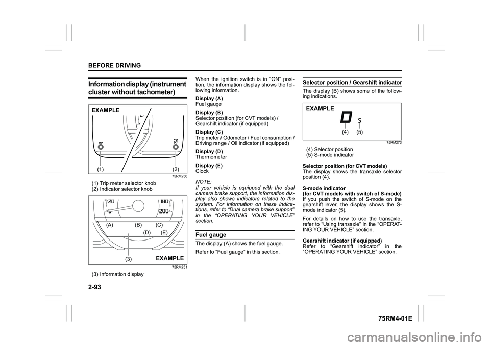
Information display (instrument cluster without tachometer)
75RM250
(1) Trip meter selector knob
(2) Indicator selector knob
75RM251
(3) Information display When the ignition switch is in “ON” posi-
tion, the information display shows the fol-
lowing information.
Display (A)
Fuel gauge
Display (B)
Selector position (for CVT models) /
Gearshift indicator (if equipped)
Display (C)
Trip meter / Odometer / Fuel consumption /
Driving range / Oil indicator (if equipped)
Display (D)
Thermometer
Display (E)
Clock
NOTE:
If your vehicle is equipped with the dual
camera brake support, the information dis-
play also shows indicators related to the
system. For information on these indica-
tions, refer to “Dual camera brake support”
in the “OPERATING YOUR VEHICLE”
section.
Fuel gaugeThe display (A) shows the fuel gauge.
Refer to “Fuel gauge” in this section.
Selector position
/ Gearshift indicatorThe display (B) shows some of the follow-
ing indications.
75RM273
(4) Selector position
(5) S-mode indicator
Selector position (for CVT models)
The display shows the transaxle selector
position (4).
S-mode indicator
(for CVT models with switch of S-mode)
If you push the switch of S-mode on the
gearshift lever, the display shows the S-
mode indicator (5).
For details on how to use the transaxle,
refer to “Using transaxle” in the “OPERAT-
ING YOUR VEHICLE” section.
Gearshift indicator (if equipped)
Refer to “Gearshift indicator” in the
“OPERATING YOUR VEHICLE” section.
(1)
(2)
EXAMPLE
(3)
(A) (B) (C)
(D) (E)
EXAMPLE
(4)
(5)
EXAMPLE
Page 130 of 505
2-107BEFORE DRIVING
75RM4-01E
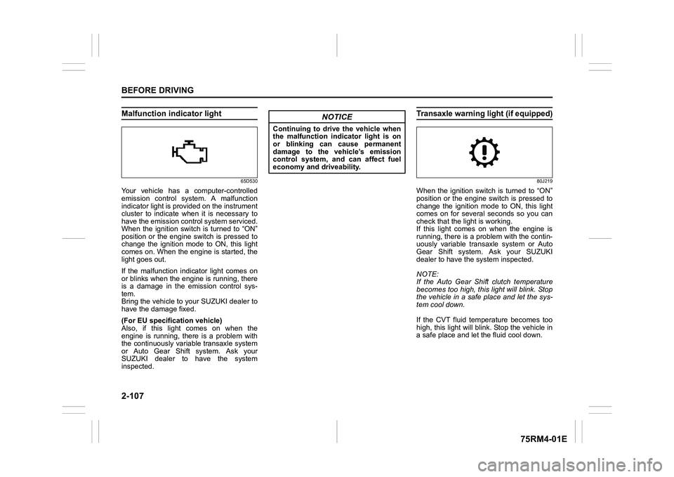
Malfunction indicator light
65D530
Your vehicle has a computer-controlled
emission control system. A malfunction
indicator light is provided on the instrument
cluster to indicate when it is necessary to
have the emission control system serviced.
When the ignition switch is turned to “ON”
position or the engine switch is pressed to
change the ignition mode to ON, this light
comes on. When the engine is started, the
light goes out.
If the malfunction indicator light comes on
or blinks when the engine is running, there
is a damage in the emission control sys-
tem.
Bring the vehicle to your SUZUKI dealer to
have the damage fixed.
(For EU specifi cation vehicle)
Also, if this light comes on when the
engine is running, there is a problem with
the continuously variable transaxle system
or Auto Gear Shift system. Ask your
SUZUKI dealer to have the system
inspected.
Transaxle warning light (if equipped)
80J219
When the ignition switch is turned to “ON”
position or the engine switch is pressed to
change the ignition mode to ON, this light
comes on for several seconds so you can
check that the light is working.
If this light comes on when the engine is
running, there is a problem with the contin-
uously variable transaxle system or Auto
Gear Shift system. Ask your SUZUKI
dealer to have t he system inspected.
NOTE:
If the Auto Gear Shift clutch temperature
becomes too high, this light will blink. Stop
the vehicle in a safe place and let the sys-
tem cool down.
If the CVT fluid temperature becomes too
high, this light will blink. Stop the vehicle in
a safe place and let the fluid cool down.
NOTICE
Continuing to drive the vehicle when
the malfunction indicator light is on
or blinking can cause permanent
damage to the vehicle’s emission
control system, and can affect fuel
economy and driveability.