gears SUZUKI IGNIS 2021 Owners Manual
[x] Cancel search | Manufacturer: SUZUKI, Model Year: 2021, Model line: IGNIS, Model: SUZUKI IGNIS 2021Pages: 505, PDF Size: 8.36 MB
Page 17 of 505
ILLUSTRATED TABLE OF CONTENTS
75RM4-01E
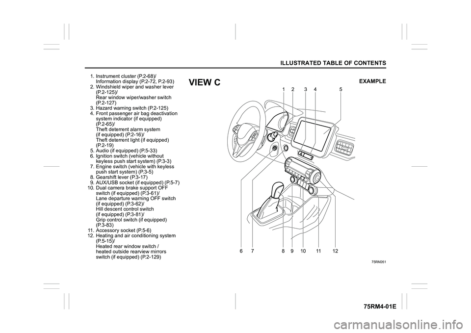
1. Instrument cluster (P.2-68)/Information display (P.2-72, P.2-93)
2. Windshield wiper and washer lever
(P.2-125)/
Rear window wiper/washer switch
(P.2-127)
3. Hazard warning switch (P.2-125)
4. Front passenger air bag deactivation system indicator (if equipped)
(P.2-65)/
Theft deterren t alarm system
(if equipped) (P.2-16)/
Theft deterrent light (if equipped)
(P.2-19)
5. Audio (if equipped) (P.5-33)
6. Ignition switch (vehicle without keyless push start system) (P.3-3)
7. Engine switch (v ehicle with keyless
push start system) (P.3-5)
8. Gearshift lever (P.3-17)
9. AUX/USB socket (if equipped) (P.5-7)
10. Dual camera brake support OFF switch (if equipped) (P.3-61)/
Lane departure warning OFF switch
(if equipped) (P.3-62)/
Hill descent control switch
(if equipped) (P.3-81)/
Grip control switch (if equipped)
(P.3-83)
11. Accessory socket (P.5-6)
12. Heating and air co nditioning system
(P.5-15)/
Heated rear window switch /
heated outside rearview mirrors
switch (if equipped) (P.2-129)
75RM261
6
79
10 11
812 12
5
34
EXAMPLE
VIEW C
Page 96 of 505
2-73BEFORE DRIVING
75RM4-01E
75RM183
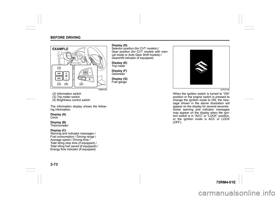
(2) Information switch
(3) Trip meter switch
(4) Brightness control switch
The information display shows the follow-
ing information.
Display (A)
Clock
Display (B)
Thermometer
Display (C)
Warning and indicator messages /
Fuel consumption / Driving range /
Average speed / Driving time /
Total idling stop time (if equipped) /
Total idling fuel saved (if equipped) /
Energy flow indicator (if equipped) Display (D)
Selector position (for CVT models) /
Gear position (for CVT models with man-
ual mode or Auto Gear Shift models) /
Gearshift indicator (if equipped)
Display (E)
Trip meter
Display (F)
Odometer
Display (G)
Fuel gauge
81P31150
When the ignition switch is turned to “ON”
position or the engine switch is pressed to
change the ignition mode to ON, the mes-
sage shown in the above illustration will
appear on the display
for several seconds.
Some warning and indicator messages
may appear on the display when the igni-
tion switch is in “ACC” or “LOCK” position,
or the ignition mode is ACC or LOCK
(OFF).
(4)
(2)(3)
(2)
EXAMPLE
Page 100 of 505
2-77BEFORE DRIVING
75RM4-01E
Total idling fuel saved (if equipped)
The display shows the total amount (in mil-
liliters) of fuel conservation by ENG A-
STOP system since the indication was
reset.
• To reset the total idling fuel saved tozero, push and hold the information
switch (2) for a while when the display
shows the total idling fuel saved.
NOTE:
When you reconnect the negative (–) ter-
minal to the lead-acid battery, the value of
the total idling fuel saved will be reset.
Energy flow indicator (if equipped)
Refer to “ENG A-ST OP system (engine
auto stop start system)” in the “OPERAT-
ING YOUR VEHICLE” section.
Selector position / Gear position / Gearshift indicatorThe display (D) shows some of the follow-
ing indications.
75RM318
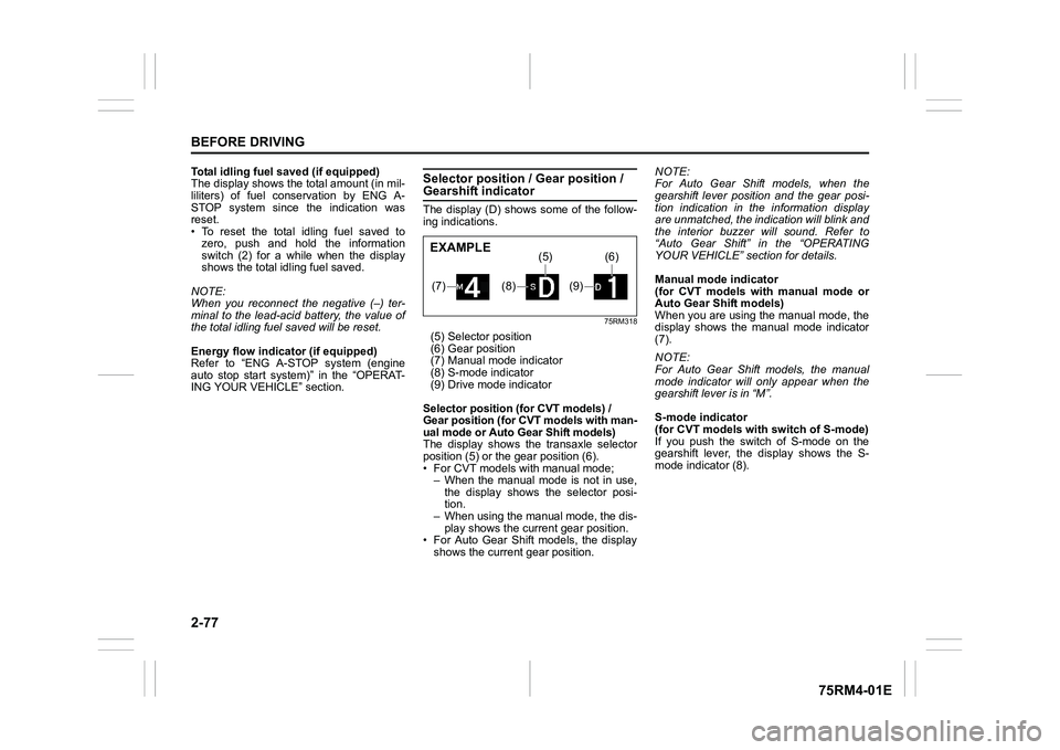
(5) Selector position
(6) Gear position
(7) Manual mode indicator
(8) S-mode indicator
(9) Drive mode indicator
Selector position (for CVT models) /
Gear position (for CVT models with man-
ual mode or Auto Gear Shift models)
The display shows th e transaxle selector
position (5) or the gear position (6).
• For CVT models with manual mode; – When the manual mode is not in use,
the display shows the selector posi-
tion.
– When using the manual mode, the dis-
play shows the current gear position.
• For Auto Gear Shift models, the display shows the current gear position. NOTE:
For Auto Gear Shif
t models, when the
gearshift lever position and the gear posi-
tion indication in the information display
are unmatched, the indication will blink and
the interior buzzer will sound. Refer to
“Auto Gear Shift” in the “OPERATING
YOUR VEHICLE” section for details.
Manual mode indicator
(for CVT models with manual mode or
Auto Gear Shift models)
When you are using the manual mode, the
display shows the manual mode indicator
(7).
NOTE:
For Auto Gear Shift models, the manual
mode indicator will only appear when the
gearshift lever is in “M”.
S-mode indicator
(for CVT models with switch of S-mode)
If you push the switch of S-mode on the
gearshift lever, the display shows the S-
mode indicator (8).(7)
(8)
(5)
(9)
(6)
EXAMPLE
Page 101 of 505
2-78
BEFORE DRIVING
75RM4-01E
Drive mode indicator
(for Auto Gear Shift models)
When the gearshift lever is in “D”, the dis-
play shows the drive mode indicator (9).
For details on how to use the transaxle,
refer to “Using transaxle” in the “OPERAT-
ING YOUR VEHICLE” section.
Gearshift indicator (if equipped)
Refer to “Gearshift indicator” in the
“OPERATING YOUR VEHICLE” section.
Trip meterThe display (E) shows the trip meter.
The trip meter can be used to measure the
distance traveled on short trips or between
fuel stops.
You can use trip meter A or trip meter B
independently.
To reset the trip meter to zero, push and
hold the trip meter swi tch (3) for a while.
NOTE:
The indicated maximum value of the trip
meter is 9999.9. When you run past the
maximum value, the indicated value will
return to 0.0.OdometerThe display (F) s hows the odometer.
The odometer records the total distance
the vehicle has been driven.
Fuel gaugeThe display (G) shows the fuel gauge.
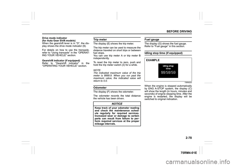
Refer to “Fuel gauge” in this section.Idling stop time (if equipped)
75RM320
When the engine is stopped automatically
by ENG A-STOP system, the display (C)
will show the length (in hours, minutes and
seconds) of engine stopping time. After the
engine is restarted, the display will be
switched to original indication.
NOTICE
Keep track of your odometer reading
and check the maintenance sched-
ule regularly for required services.
Increased wear or damage to certain
parts can result from failure to per-
form required services at the proper
mileage intervals.
EXAMPLE
Page 111 of 505
2-88
BEFORE DRIVING
75RM4-01E
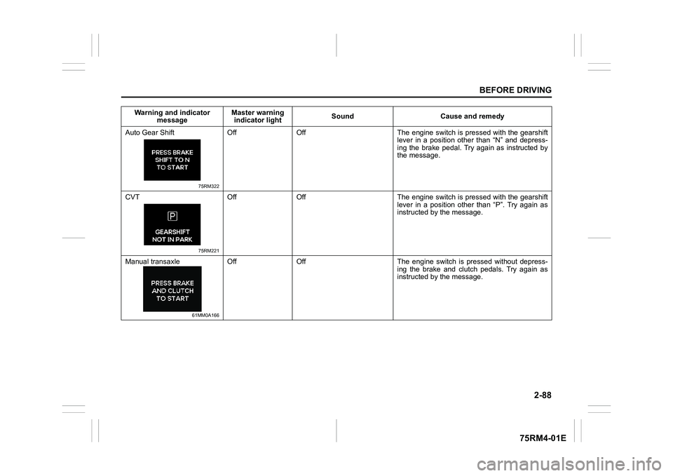
Auto Gear Shift
75RM322
Off Off The engine switch is pressed with the gearshiftlever in a position other than “N” and depress-
ing the brake pedal. Try again as instructed by
the message.
CVT
75RM221
Off Off The engine switch is pressed with the gearshift lever in a position other than “P”. Try again as
instructed by the message.
Manual transaxle
61MM0A166
Off Off The engine switch is pressed without depress- ing the brake and clutch pedals. Try again as
instructed by the message.
Warning and indicator
message Master warning
indicator light Sound Cause and remedy
Page 116 of 505
2-93BEFORE DRIVING
75RM4-01E
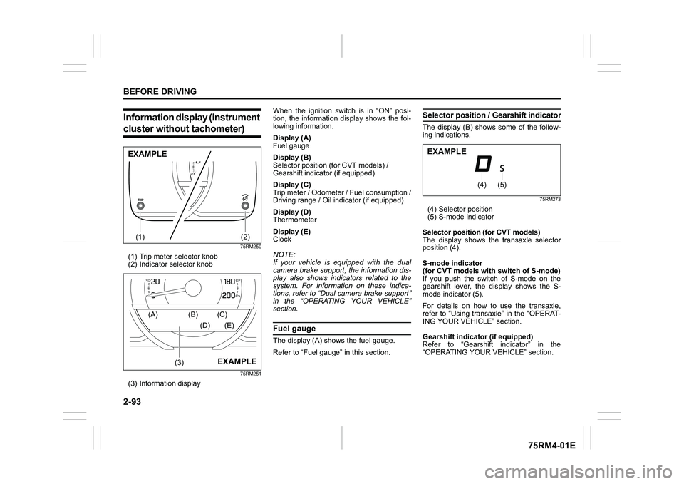
Information display (instrument cluster without tachometer)
75RM250
(1) Trip meter selector knob
(2) Indicator selector knob
75RM251
(3) Information display When the ignition switch is in “ON” posi-
tion, the information display shows the fol-
lowing information.
Display (A)
Fuel gauge
Display (B)
Selector position (for CVT models) /
Gearshift indicator (if equipped)
Display (C)
Trip meter / Odometer / Fuel consumption /
Driving range / Oil indicator (if equipped)
Display (D)
Thermometer
Display (E)
Clock
NOTE:
If your vehicle is equipped with the dual
camera brake support, the information dis-
play also shows indicators related to the
system. For information on these indica-
tions, refer to “Dual camera brake support”
in the “OPERATING YOUR VEHICLE”
section.
Fuel gaugeThe display (A) shows the fuel gauge.
Refer to “Fuel gauge” in this section.
Selector position
/ Gearshift indicatorThe display (B) shows some of the follow-
ing indications.
75RM273
(4) Selector position
(5) S-mode indicator
Selector position (for CVT models)
The display shows the transaxle selector
position (4).
S-mode indicator
(for CVT models with switch of S-mode)
If you push the switch of S-mode on the
gearshift lever, the display shows the S-
mode indicator (5).
For details on how to use the transaxle,
refer to “Using transaxle” in the “OPERAT-
ING YOUR VEHICLE” section.
Gearshift indicator (if equipped)
Refer to “Gearshift indicator” in the
“OPERATING YOUR VEHICLE” section.
(1)
(2)
EXAMPLE
(3)
(A) (B) (C)
(D) (E)
EXAMPLE
(4)
(5)
EXAMPLE
Page 153 of 505
OPERATING YOUR VEHICLE
3
75RM4-01E
60G408
OPERATING YOUR VEHICLEExhaust gas warning .......................................................... 3-1
Daily inspection checklist .................................... .............. 3-1
Engine oil consumption ........................................ ............. 3-2
Ignition switch
(vehicle without keyless push s tart system) ....................3-3
Engine switch
(vehicle with keyless push sta rt system) .......................... 3-5
Keyless push start system (if equipped) .......................... 3-6
Parking brake lever ........................................... .................. 3-10
Pedal ......................................................... ............................ 3-12
Starting engine
(vehicle without keyless push s tart system) ....................3-13
Starting engine
(vehicle with keyless push sta rt system) .......................... 3-14
Using transaxle ... ....................... ......................................... 3-17
Gearshift indicator (if equipped) ............................. ........... 3-33
ENG A-STOP system
(engine auto stop start system) (if equipped) ................. .3-35
Cruise control (if equipped) ............................................... 3-48
Speed limiter (if equipped) ................................... .............. 3-51
Dual camera brake support (if equipped) ......................... 3-53
Emergency stop signal (ESS) (if equipped) ......................3-71
Rearview camera (if equipped) ................................. ......... 3-72
Braking ....................................................... .......................... 3-75
Electronic stabi lity program (ESP
®) (if equipped) ........... 3-78
Tire pressure monito ring system (TPMS) (i f equipped) .. 3-85
Page 157 of 505
3-4
OPERATING YOUR VEHICLE
75RM4-01E
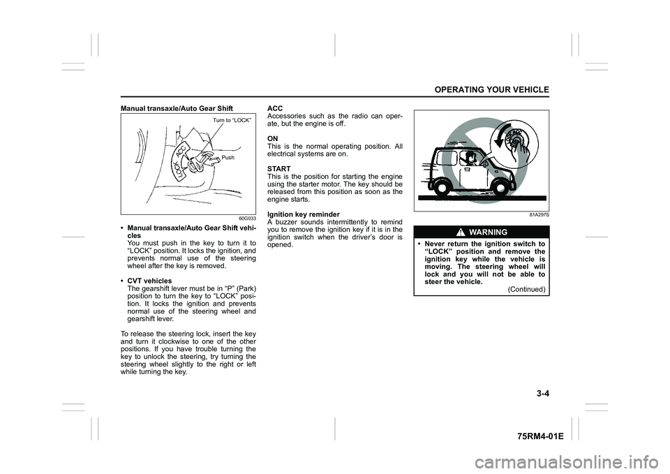
Manual transaxle/Auto Gear Shift
60G033
• Manual transaxle/Auto Gear Shift vehi-cles
You must push in the key to turn it to
“LOCK” position. It lo cks the ignition, and
prevents normal use of the steering
wheel after the key is removed.
• CVT vehicles The gearshift lever must be in “P” (Park)
position to turn the key to “LOCK” posi-
tion. It locks the ignition and prevents
normal use of the steering wheel and
gearshift lever.
To release the steering lock, insert the key
and turn it clockwis e to one of the other
positions. If you have trouble turning the
key to unlock the steering, try turning the
steering wheel slightly to the right or left
while turning the key. ACC
Accessories such as the radio can oper-
ate, but the engine is off.
ON
This is the normal operating position. All
electrical systems are on.
START
This is the position for starting the engine
using the starter motor. The key should be
released from this position as soon as the
engine starts.
Ignition key reminder
A buzzer sounds intermittently to remind
you to remove the ignition key if it is in the
ignition switch when the driver’s door is
opened.
81A297S
Turn to “LOCK”
Push
WA R N I N G
• Never return the ignition switch to“LOCK” position and remove the
ignition key while the vehicle is
moving. The steering wheel will
lock and you will not be able to
steer the vehicle. (Continued)
Page 159 of 505
3-6
OPERATING YOUR VEHICLE
75RM4-01E
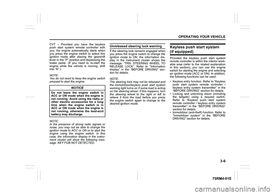
CVT – Provided you have the keyless
push start system remote controller with
you, the engine automatically starts when
you press the engine switch to select this
ignition mode after placing the gearshift
lever in the “P” position and depressing the
brake pedal. (If you need to re-start the
engine while the vehicle is moving, shift
into “N”.)
NOTE:
You do not need to keep the engine switch
pressed to start the engine.
NOTE:
In the presence of strong radio signals or
noise, you may not be able to change the
ignition mode to ACC or ON or to start the
engine using the engine switch. In this
case, the information display in the instru-
ment cluster will show the following mes-
sage: KEY FOB NOT DETECTED.
Unreleased steering lock warningIf the steering lock remains engaged when
you press the engine switch to change the
ignition mode to ON, the information dis-
play in the instrument cluster shows the
message: “TRN. STEERING WHEEL TO
RELEASE LOCK”. Refer to “Information
display” in the “BEFORE DRIVING” sec-
tion for details.
NOTE:
The steering lock may not be released and
the immobilizer/keyless push start system
warning light turns on if some load is acting
on the steering wheel . If this happens, turn
the steering wheel to the right or left to
relieve it from the load before you press
the engine switch again to change to the
desired ignition mode.
Keyless push start system (if equipped)Provided the keyless push start system
remote controller is within the interior work-
able area (refer to the related explanation
in this section), you can use the engine
switch for starting the engine and selecting
an ignition mode (ACC or ON). In addition,
the following functions can be used:
• Keyless entry function. Refer to “Keyless push start system r emote controller /
keyless entry system transmitter” in the
“BEFORE DRIVING” se ction for details.
• Locking and unlocking doors (including the tailgate) using a request switch.
Refer to “Keyless push start system
remote controller / keyless entry system
transmitter” in the “BEFORE DRIVING”
section for details.
• Immobilizer (anti-thef t) function. Refer to
“Immobilizer syste m” in the “BEFORE
DRIVING” section for details.
NOTICE
Do not leave the engine switch in
ACC or ON mode when the engine is
not running. Avoid using the radio or
other electric accessories for a long
time when the engine switch is in
ACC or ON mode when the engine is
not running, other wise the lead-acid
battery may discharge.
Page 160 of 505
3-7OPERATING YOUR VEHICLE
75RM4-01E
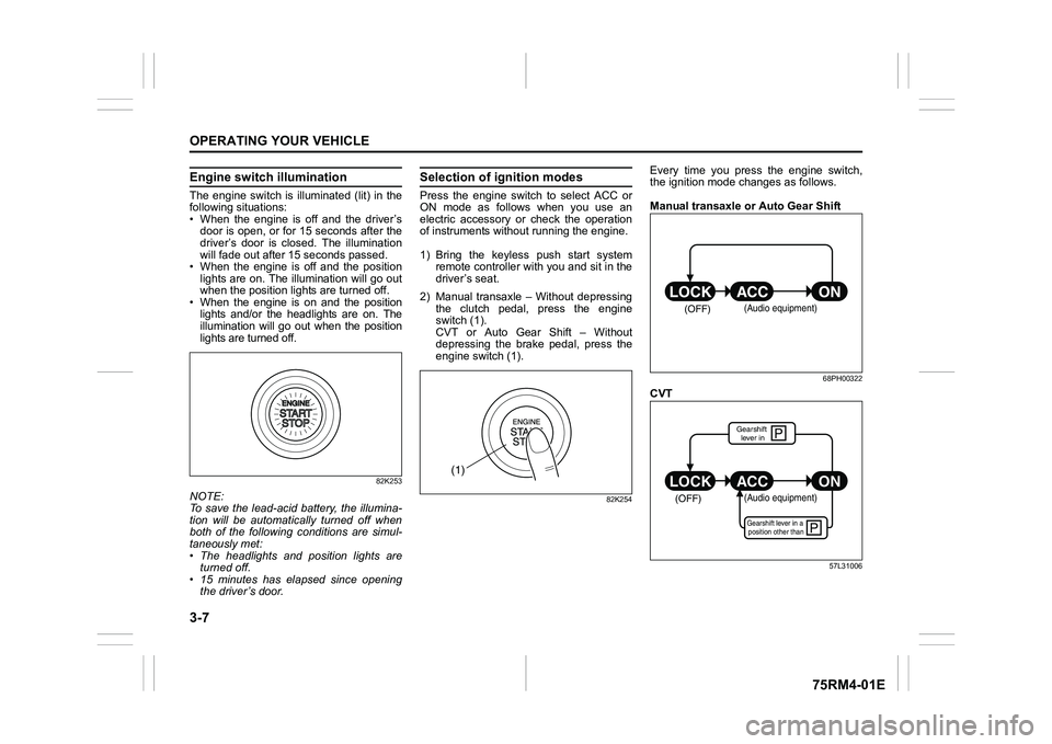
Engine switch illuminationThe engine switch is illuminated (lit) in the
following situations:
• When the engine is off and the driver’sdoor is open, or for 15 seconds after the
driver’s door is closed. The illumination
will fade out after 15 seconds passed.
• When the engine is off and the position lights are on. The illumination will go out
when the position lig hts are turned off.
• When the engine is on and the position lights and/or the headlights are on. The
illumination will go out when the position
lights are turned off.
82K253
NOTE:
To save the lead-acid battery, the illumina-
tion will be automatically turned off when
both of the following conditions are simul-
taneously met:
• The headlights and position lights areturned off.
• 15 minutes has elapsed since opening
the driver’s door.
Selection of i gnition modesPress the engine switch to select ACC or
ON mode as follows when you use an
electric accessory or check the operation
of instruments without running the engine.
1) Bring the keyless push start system remote controller with you and sit in the
driver’s seat.
2) Manual transaxle – Without depressing the clutch pedal, press the engine
switch (1).
CVT or Auto Gear Shift – Without
depressing the brake pedal, press the
engine switch (1).
82K254
Every time you press the engine switch,
the ignition mode changes as follows.
Manual transaxle or Auto Gear Shift
68PH00322
CVT
57L31006
(1)
(OFF)
(Audio equipment)
�çP
P
(OFF)
ON
ACC
LOCK
(Audio equipment)Gearshift lever in a
position other thanGearshift lever in