Fuel light SUZUKI IGNIS 2022 User Guide
[x] Cancel search | Manufacturer: SUZUKI, Model Year: 2022, Model line: IGNIS, Model: SUZUKI IGNIS 2022Pages: 505, PDF Size: 8.36 MB
Page 124 of 505
2-101BEFORE DRIVING
75RM4-01E
Warning and indicator lightsNOTE:
If warning and indicator lights blink or
come on, the corresponding messages
may be shown on the information display.Low tire pressure warning light (if equipped)
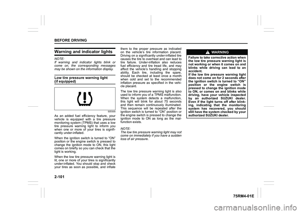
52D305
As an added fuel efficiency feature, your
vehicle is equipped with a tire pressure
monitoring system (TPMS) that uses a low
tire pressure warning light to inform you
when one or more of your tires is signifi-
cantly under-inflated.
When the ignition switch is turned to “ON”
position or the engine switch is pressed to
change the ignition mode to ON, this light
comes on briefly so you can check that the
light is working.
When the low tire pressure warning light is
lit, one or more of your tires is significantly
under-inflated. You should stop and check
your tires as soon as possible, and inflate them to the proper pressure as indicated
on the vehicle’s tire information placard.
Driving on a significantly under-inflated tire
causes the tire to overheat and can lead to
tire failure. Under-inf
lation also reduces
fuel efficiency and tire tread life, and may
affect the vehicle’s handling and stopping
ability. Each tire, including the spare,
should be checked at least once a month
when cold and set to the recommended
inflation pressure as specified in the vehi-
cle placard.
The low tire pressure warning light is also
used to inform you of a TPMS malfunction.
When the system detects a malfunction,
this light will blink for about 75 seconds
and then remain continuously illuminated.
This sequence will be repeated after the
ignition switch is turned to “ON” position or
the engine switch is pressed to change the
ignition mode to ON as long as the mal-
function exists.
NOTE:
The low tire pressure warning light may not
come on immediately if you have a sudden
loss of air pressure.
WA R N I N G
Failure to take corrective action when
the low tire pressure warning light is
not working or when it comes on and
blinks while driving can lead to an
accident.
If the low tire pressure warning light
does not come on for 2 seconds after
the ignition switch is turned to “ON”
position or the engine switch is
pressed to change the ignition mode
to ON, or comes on and blinks while
driving, have your vehicle inspected
by an authorized SUZUKI dealer.
Even if the light tu rns off after blink-
ing, indicating that the monitoring
system has recovered, you should
still have the system checked by your
authorized SUZUKI dealer.
Page 130 of 505
2-107BEFORE DRIVING
75RM4-01E
Malfunction indicator light
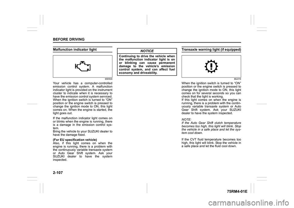
65D530
Your vehicle has a computer-controlled
emission control system. A malfunction
indicator light is provided on the instrument
cluster to indicate when it is necessary to
have the emission control system serviced.
When the ignition switch is turned to “ON”
position or the engine switch is pressed to
change the ignition mode to ON, this light
comes on. When the engine is started, the
light goes out.
If the malfunction indicator light comes on
or blinks when the engine is running, there
is a damage in the emission control sys-
tem.
Bring the vehicle to your SUZUKI dealer to
have the damage fixed.
(For EU specifi cation vehicle)
Also, if this light comes on when the
engine is running, there is a problem with
the continuously variable transaxle system
or Auto Gear Shift system. Ask your
SUZUKI dealer to have the system
inspected.
Transaxle warning light (if equipped)
80J219
When the ignition switch is turned to “ON”
position or the engine switch is pressed to
change the ignition mode to ON, this light
comes on for several seconds so you can
check that the light is working.
If this light comes on when the engine is
running, there is a problem with the contin-
uously variable transaxle system or Auto
Gear Shift system. Ask your SUZUKI
dealer to have t he system inspected.
NOTE:
If the Auto Gear Shift clutch temperature
becomes too high, this light will blink. Stop
the vehicle in a safe place and let the sys-
tem cool down.
If the CVT fluid temperature becomes too
high, this light will blink. Stop the vehicle in
a safe place and let the fluid cool down.
NOTICE
Continuing to drive the vehicle when
the malfunction indicator light is on
or blinking can cause permanent
damage to the vehicle’s emission
control system, and can affect fuel
economy and driveability.
Page 131 of 505
2-108
BEFORE DRIVING
75RM4-01E
Immobilizer/keyless push start sys-tem warning light
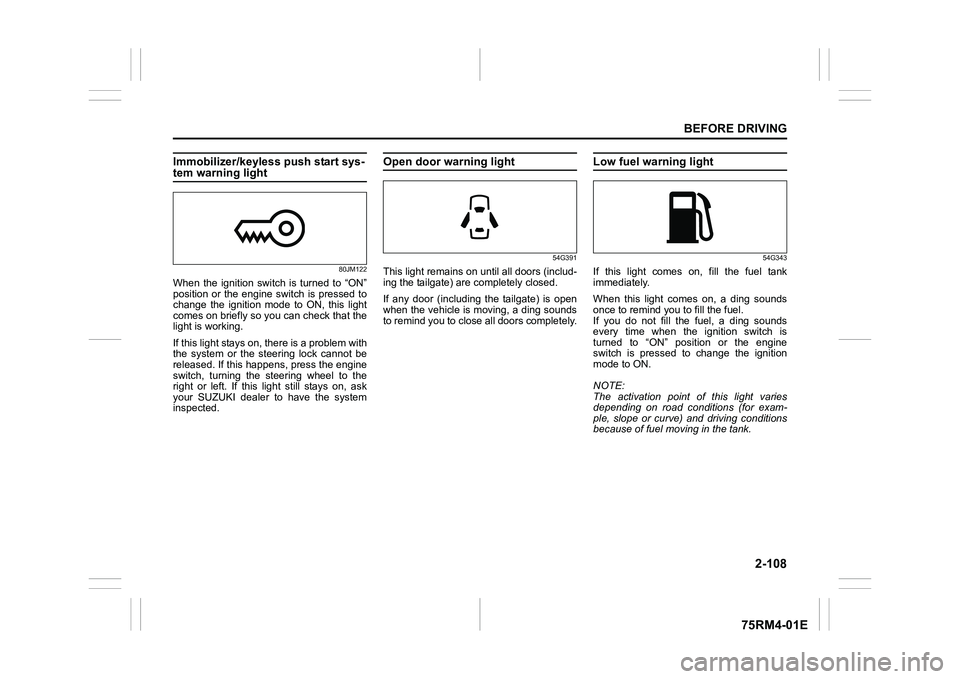
80JM122
When the ignition switch is turned to “ON”
position or the engine switch is pressed to
change the ignition mode to ON, this light
comes on briefly so you can check that the
light is working.
If this light stays on, there is a problem with
the system or the steering lock cannot be
released. If this happens, press the engine
switch, turning the steering wheel to the
right or left. If this light still stays on, ask
your SUZUKI dealer to have the system
inspected.
Open door warning light
54G391
This light remains on until all doors (includ-
ing the tailgate) are completely closed.
If any door (including the tailgate) is open
when the vehicle is moving, a ding sounds
to remind you to close all doors completely.
Low fuel warning light
54G343
If this light comes on, fill the fuel tank
immediately.
When this light comes on, a ding sounds
once to remind you to fill the fuel.
If you do not fill the fuel, a ding sounds
every time when the ignition switch is
turned to “ON” position or the engine
switch is pressed to change the ignition
mode to ON.
NOTE:
The activation point of this light varies
depending on road conditions (for exam-
ple, slope or curve) and driving conditions
because of fuel moving in the tank.
Page 155 of 505
3-2
OPERATING YOUR VEHICLE
75RM4-01E
NOTE:
It is normal for water to drip from the air
conditioning system after use.
4) Check that the hood is fully closed andlatched.
5) Check the headlights, turn signal lights, brake lights and horn for proper opera-
tion.
6) Adjust the seat and head restraint.
7) Check the brake pedal and the parking brake lever.
8) Adjust the mirrors.
9) Check that you and all passengers have properly fastened your seat belts.
10)Check that all warning lights come on as the ignition switch is turned to “ON”
position or the engine switch is pressed
to change the ignition mode to ON.
11)Check all gauges.
12)Check that the brake system warning light turns off when the parking brake is
released.
Once a week, or each time you fill your fuel
tank, perform the following under-hood
checks:
1) Engine oil level
2) Coolant level
3) Brake fluid level
4) Lead-acid battery solution level
5) Windshield washer fluid level
6) Hood latch operation Pull the hood release handle inside the
vehicle. Check that you cannot open the hood all the way without releasing
the secondary latch. Close the hood
securely after checking for proper latch
operation. See the item “All latches,
hinges and locks” of “Chassis, body
and others” in “Maintenance schedule”
in the “INSPECTION AND MAINTE-
NANCE” section for lubrication sched-
ule.
Once a month, or each time you fill your
fuel tank, check the tire pressure using a
tire pressure gauge. Also check the tire
pressure of the spare tire.
Engine oil consumptionIt is normal for the engine to consume
some engine oil during normal vehicle
operation.
The amount of engine oil consumption
depends on viscosity and quality of the oil
and your driving conditions.
More oil is consumed during high-speed
driving and when there is frequent acceler-
ation and deceleration. Under high loads,
your engine also will consume more oil.
A new engine also consumes more oil,
since its pistons, piston rings and cylinder
walls have not yet become conditioned.
New engines reach the normal level of oil
consumption only after approximately
5000 km (3000 miles) driving.
Oil consumption:
Max. 1.0 L per 1000 km
(1 Qt. per 600 miles)
When judging the amount of oil consump-
tion, note that the oil may become diluted
and it is difficult to judge the accurate oil
level.
As an example, if a vehicle is used for
repeated short trips, and consumes a nor-
mal amount of oil, the dipstick may not
show any drop in the oil level at all, even
after 1000 km (600 miles) or more of driv-
ing. This is because the oil gradually
becomes diluted with fuel or moisture,
WA R N I N G
Check that the hood is fully closed
and latched before d riving. If it is not,
it can fly up unexpectedly during
driving, obstructing your view and
resulting in an accident.
Page 190 of 505
3-37OPERATING YOUR VEHICLE
75RM4-01E
• The audio and other electrical compo-nent can be used during the automatic
engine stop, but the air conditioner will
switch to the fan mode.
• If the vehicle is equipped with the auto- matic heating and air conditioning sys-
tem, the fan speed will be limited during
the automatic engine stop (only in the
auto control mode) to keep the cabin air-
conditioned for a longer time.
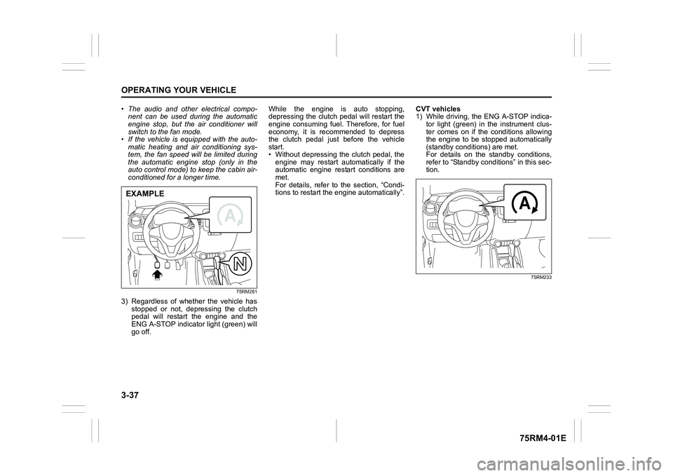
75RM281
3) Regardless of whether the vehicle has
stopped or not, depressing the clutch
pedal will restart the engine and the
ENG A-STOP indicator light (green) will
go off. While the engine is auto stopping,
depressing the clutch pedal will restart the
engine consuming fuel. Therefore, for fuel
economy, it is recommended to depress
the clutch pedal just before the vehicle
start.
• Without depressing the clutch pedal, the
engine may restart automatically if the
automatic engine restart conditions are
met.
For details, refer to the section, “Condi-
tions to restart the engine automatically”. CVT vehicles
1) While driving, the ENG A-STOP indica-
tor light (green) in the instrument clus-
ter comes on if the conditions allowing
the engine to be stopped automatically
(standby conditions) are met.
For details on the standby conditions,
refer to “Standby conditions” in this sec-
tion.
75RM233
EXAMPLE
Page 238 of 505
3-85OPERATING YOUR VEHICLE
75RM4-01E
On models equipped with the ENG A-
STOP system, the hill hold control system
is activated when the engine is restarted
after being stopped automatically, even if
the previous conditions are not met.
NOTE:
When the hill hold control system is acti-
vated, you may hear a sound coming from
the engine, or you may feel hardness of
the brake pedal. These are normal and do
not indicate a malfunction.
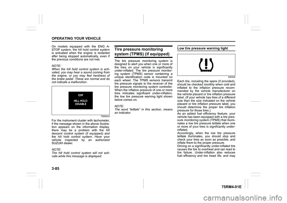
75RM224
For the instrument cluster with tachometer,
if the message shown in the above illustra-
tion appears on the information display,
there may be a problem with the hill
descent control system (if equipped) and
the hill hold control system. Have your
vehicle inspected by an authorized
SUZUKI dealer.
NOTE:
The hill hold control system will not acti-
vate while this message is displayed.
Tire pressure monitoring system (TPMS) (if equipped)The tire pressure monitoring system is
designed to alert you when one or more of
the tires on your vehicle is significantly
under-inflated. The tire pressure monitor-
ing system (TPMS) sensor containing a
unique identification code is mounted on
each wheel. The TPMS sensors transmit
tire pressure signals to the receiver of the
tire pressure monitoring system controller.
When the inflation pressure of one or more
tires indicates signif icant under-inflation,
the low tire pressure warning light shown
below comes on.
NOTE:
The word “telltale” in this section, means
an indicator.
Low tire pressure warning light
52D305
Each tire, including the spare (if provided),
should be checked monthly when cold and
inflated to the inflation pressure recom-
mended by the vehicle manufacturer on
the vehicle placard or tire inflation pressure
label. (If your vehicle has tires of a different
size than the size indicated on the vehicle
placard or tire inflation pressure label, you
should determine the proper tire inflation
pressure for those tires.)
As an added fuel efficiency feature, your
vehicle has been equipped with a tire pres-
sure monitoring system (TPMS) that illumi-
nates a low tire pressure telltale when one
or more of your tires is significantly under-
inflated.
Accordingly, when the low tire pressure
telltale illuminates, you should stop and
check your tires as soon as possible, and
inflate them to the proper pressure.
Driving on a significantly under-inflated tire
causes the tire to overheat and can lead to
tire failure. Under-inf lation also reduces
fuel efficiency and tire tread life, and may
Page 249 of 505
4-2
DRIVING TIPS
75RM4-01E
heat damage to the catalytic converter and
other vehicle components.
54G584S
Improving fuel economyThe following instructions will help you
improve fuel economy.
Avoid excessive idling
If you are to wait for more than a minute
while you are parked, stop the engine and
start it again later. When warming up a
cold engine, do not allow the engine to idle
or apply full throttle until the engine has
reached operating temperature. Allow the
engine to warm up by driving.
Avoid fast starts
Fast starts away from lights or stop signs
will consume fuel unnecessarily and
shorten engine life. Start off slowly.
Avoid unnecessary stops
Avoid unnecessary deceleration and stop-
ping. Try to maintain a slow, steady speed
whenever possible. Slowing down and
then accelerating aga in uses more fuel.
Keep a steady cruising speed
Drive at a constant speed that road and
traffic conditions will permit.
NOTICE
To minimize the possibility of cata-
lytic converter or other vehicle dam-
age:
• Maintain the engine in the proper operating condition.
• In the event of an engine malfunc-
tion, particularly one involving
engine misfire or other apparent
loss of performance, have the vehi-
cle serviced promptly.
• Do not turn off the engine or inter-
rupt the ignition when the transaxle
is in gear and the vehicle is in
motion.
• Do not try to start the engine by pushing or towing the vehicle, or
coasting down a hill.
• Do not idle the engine with any spark plug wires disconnected or
removed, such as during diagnos-
tic testing.
• Do not idle the vehicle for pro- longed periods if idling seems
rough or there are other malfunc-
tions.
• Do not allow the fuel tank to get
near the empty level.
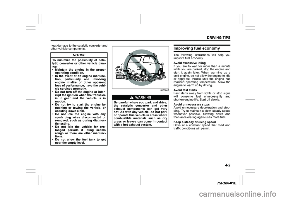
WA R N I N G
Be careful where you park and drive;
the catalytic converter and other
exhaust components can get very
hot. As with any vehicle, do not park
or operate this vehicle in areas where
combustible materials such as dry
grass or leaves can come in contact
with a hot exhaust system.
Page 255 of 505
OTHER CONTROLS AND EQUIPMENT
5
75RM4-01E
60G407
OTHER CONTROLS AND EQUIPMENTFuel filler cap ....................................................................... 5-1
Engine hood ................................................... ..................... 5-2
Sun visor ..................................................... ......................... 5-4
Interior light ................................................ ......................... 5-5
Accessory socket .............. ....................... ........................... 5-6
AUX/USB socket (if equipped) . .......................................... 5-7
Assist grips (if equipped) .................................... ............... 5-7
Glove box ..................................................... ........................ 5-7
Cup holder and storage area ................................... .......... 5-8
Footrest ...................................................... .......................... 5-10
Floor mats .................................................... ........................ 5-10
Luggage compartment cover (if equipped) ...................... 5 -11
Roof rails (if equipped) ...................................... ................. 5-11
Frame hooks ................................................... ..................... 5-12
Heating and air conditioning system ........................... ..... 5-15
Heating system ................................................ .................... 5-17
Manual heating and a ir conditioning system ................... 5 -21
Automatic heating and ai r conditioning system
(climate control) ........... ....................................................... 5-26
Radio antenna ................................................. .................... 5-32
Installation of radi o frequency transmi tters ..................... 5-32
Audio system (Type A / Type B / Type C) (if equipped) ... 5-33
Page 278 of 505
5-23OTHER CONTROLS AND EQUIPMENT
75RM4-01E
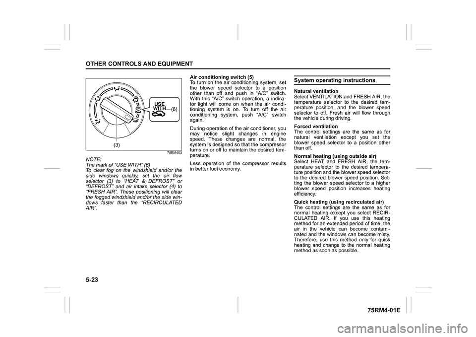
75RM403
NOTE:
The mark of “USE WITH” (6)
To clear fog on the windshield and/or the
side windows quickly, set the air flow
selector (3) to “HEAT & DEFROST” or
“DEFROST” and air intake selector (4) to
“FRESH AIR”. These positioning will clear
the fogged windshield and/or the side win-
dows faster than the “RECIRCULATED
AIR”. Air conditioning switch (5)
To turn on the air conditioning system, set
the blower speed selector to a position
other than off and push in “A/C” switch.
With this “A/C” switch operation, a indica-
tor light will come on when the air condi-
tioning system is on. To turn off the air
conditioning system,
push “A/C” switch
again.
During operation of the air conditioner, you
may notice slight changes in engine
speed. These changes are normal, the
system is designed so that the compressor
turns on or off to maintain the desired tem-
perature.
Less operation of the compressor results
in better fuel economy.
System operating instructionsNatural ventilation
Select VENTILATION and FRESH AIR, the
temperature selector to the desired tem-
perature position, and the blower speed
selector to off. Fresh air will flow through
the vehicle during driving.
Forced ventilation
The control settings are the same as for
natural ventilation except you set the
blower speed selector to a position other
than off.
Normal heating (using outside air)
Select HEAT and FRESH AIR, the tem-
perature selector to the desired tempera-
ture position and the blower speed selector
to the desired blower speed position. Set-
ting the blower speed selector to a higher
blower speed position increases heating
efficiency.
Quick heating (using recirculated air)
The control settings are the same as for
normal heating except you select RECIR-
CULATED AIR. If you use this heating
method for an extended period of time, the
air in the vehicle can become contami-
nated and the windows can become misty.
Therefore, use this method only for quick
heating and change to the normal heating
method as soon as possible.
(3)
(6)
Page 363 of 505
7-14
INSPECTION AND MAINTENANCE
75RM4-01E
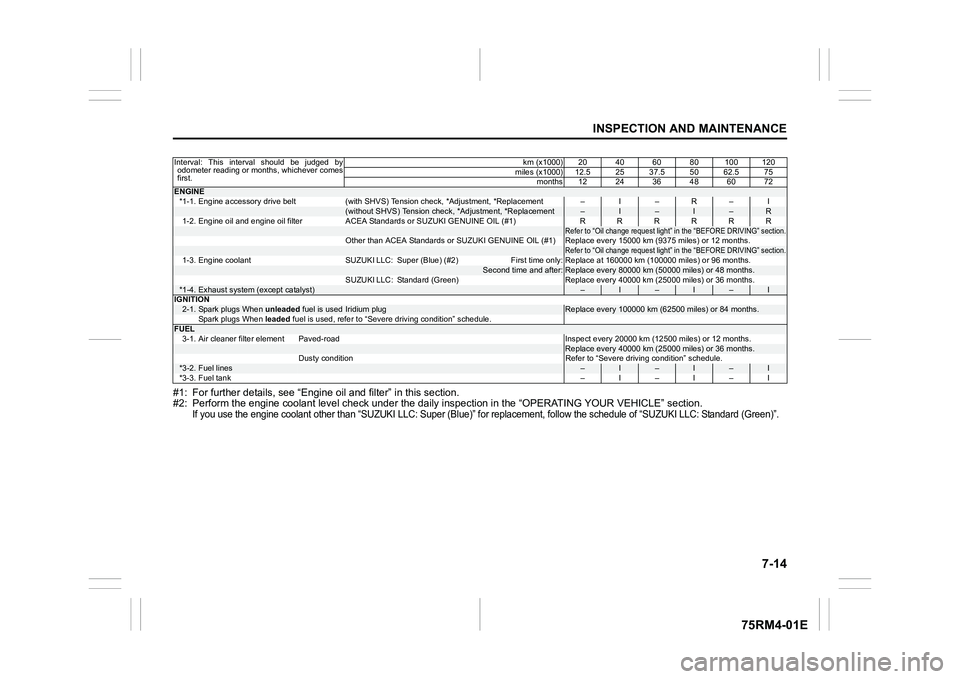
#1: For further details, see “Engine oil and filter” in this section.
#2: Perform the engine coolant l evel check under the daily inspection in the “OPERATING YOUR VEHICLE” section.
If you use the engine coolant other than “SUZUKI LLC: Super (Bl ue)” for replacement, follow the schedule of “SUZUKI LLC: Standard (Green)”.
Interval: This interval should be judged by
odometer reading or months, whichever comes
first. km (x1000) 20 40 60 80 100 120
miles (x1000) 12.5 25 37.5 50 62.5 75 months 12 24 36 48 60 72ENGINE*1-1. Engine accessory drive belt (with SHVS) Tension check, *Adjustment, *Replacement – I – R – I
(without SHVS) Tension check, *Adjustment, *Replacement
–
I
–
I
–
R
1-2. Engine oil and engine oil filter ACEA Standards or SUZUKI G ENUINE OIL (#1) RRRRRR
Refer to “Oil change request light” in the “BEFORE DRIVING” section.
Other than ACEA Standards or SUZUKI GENUINE OIL (#1) Replace eve ry 15000 km (9375 miles) or 12 months.
Refer to “Oil change request light” in the “BEFORE DRIVING” section.
1-3. Engine coolant SUZUKI LLC: Super (Blue) (#2) First time only : Replace at 160000 km (100000 miles) or 96 months.
Second time and after:
Replace every 80000 km (50000 miles) or 48 months.
SUZUKI LLC: Standard (Green) Replace every 40000 km (25000 mile s) or 36 months.
*1-4.
Exhaust system (except catalyst)
–
I
–
I
–
I
IGNITION
2-1.
Spark plugs When unleaded fuel is used
Iridium plug
Replace every 100000 km (62500 miles) or 84 months.
Spark plugs When leaded fuel is used, refer to “Severe driving condition” schedule.
FUEL
3-1. Air cleaner filter element Paved-road Inspect every 20000 k m (12500 miles) or 12 months.
Replace every 40000 km (25000 miles) or 36 months.
Dusty condition Refer to “Severe driving condition” schedule.
*3-2.
Fuel lines
–
I
–
I
–
I
*3-3. Fuel tank –I–I–I