tow SUZUKI IGNIS 2022 User Guide
[x] Cancel search | Manufacturer: SUZUKI, Model Year: 2022, Model line: IGNIS, Model: SUZUKI IGNIS 2022Pages: 505, PDF Size: 8.36 MB
Page 72 of 505
2-49BEFORE DRIVING
75RM4-01E
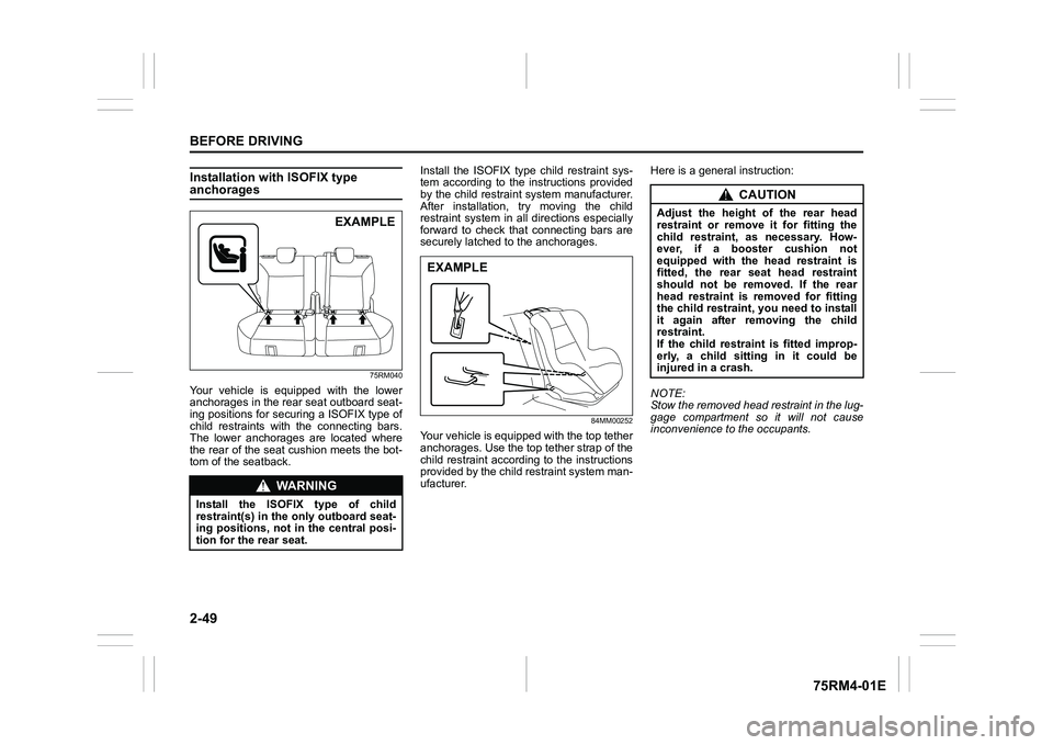
Installation with ISOFIX type anchorages
75RM040
Your vehicle is equipped with the lower
anchorages in the rear seat outboard seat-
ing positions for securing a ISOFIX type of
child restraints with the connecting bars.
The lower anchorages are located where
the rear of the seat cushion meets the bot-
tom of the seatback.Install the ISOFIX type child restraint sys-
tem according to the instructions provided
by the child restraint system manufacturer.
After installation, try moving the child
restraint system in all
directions especially
forward to check that connecting bars are
securely latched t o the anchorages.
84MM00252
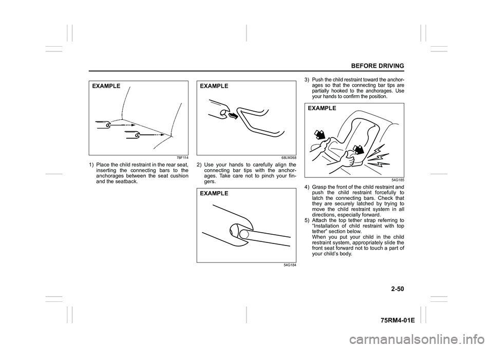
Your vehicle is equipped with the top tether
anchorages. Use the top tether strap of the
child restraint according to the instructions
provided by the child restraint system man-
ufacturer. Here is a genera
l instruction:
NOTE:
Stow the removed head restraint in the lug-
gage compartment so it will not cause
inconvenience to the occupants.
WA R N I N G
Install the ISOFIX type of child
restraint(s) in the o nly outboard seat-
ing positions, not in the central posi-
tion for the rear seat.
EXAMPLE
EXAMPLE
CAUTION
Adjust the height of the rear head
restraint or remove it for fitting the
child restraint, as necessary. How-
ever, if a booster cushion not
equipped with the head restraint is
fitted, the rear seat head restraint
should not be removed. If the rear
head restraint is removed for fitting
the child restraint, you need to install
it again after removing the child
restraint.
If the child restraint is fitted improp-
erly, a child sitting in it could be
injured in a crash.
Page 73 of 505
2-50
BEFORE DRIVING
75RM4-01E
78F114
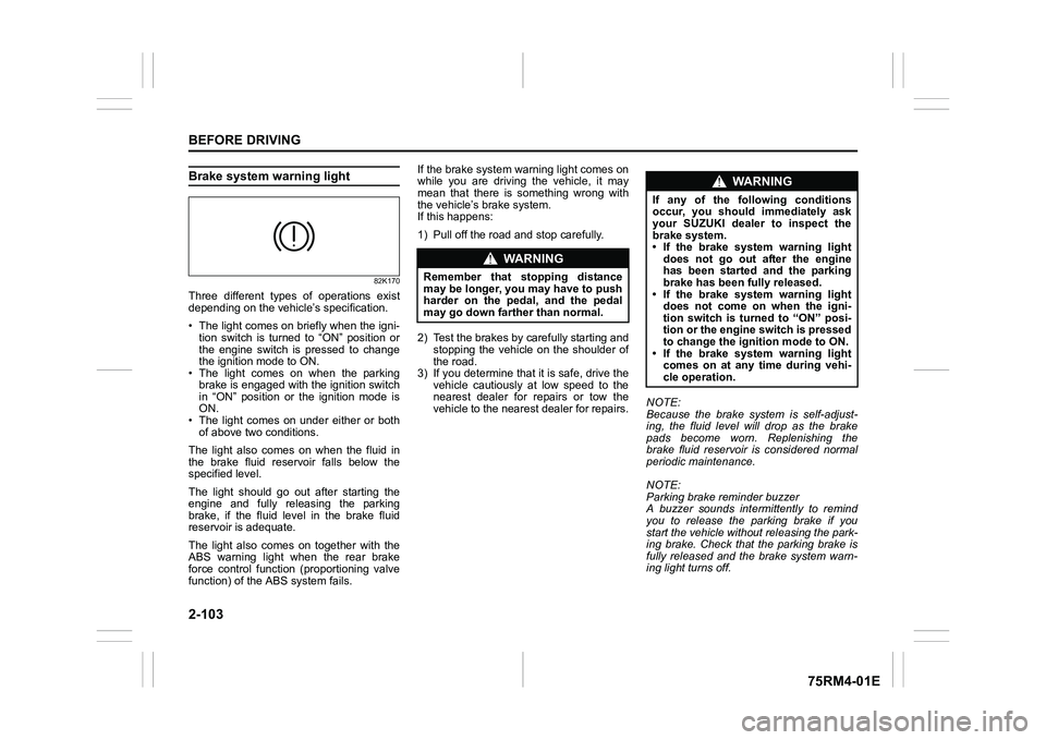
1) Place the child restraint in the rear seat,inserting the connecting bars to the
anchorages between the seat cushion
and the seatback.
68LM268
2) Use your hands to carefully align theconnecting bar tips with the anchor-
ages. Take care not to pinch your fin-
gers.
54G184
3) Push the child restraint toward the anchor- ages so that the connecting bar tips are
partially hooked to the anchorages. Use
your hands to confirm the position.
54G185
4) Grasp the front of the child restraint and
push the child restraint forcefully to
latch the connecting bars. Check that
they are securely latched by trying to
move the child restraint system in all
directions, especially forward.
5) Attach the top tether strap referring to
“Installation of child restraint with top
tether” section below.
When you put your child in the child
restraint system, appropriately slide the
front seat forward not to touch a part of
your child’s body.
EXAMPLE
EXAMPLEEXAMPLE
EXAMPLE
Page 126 of 505
2-103BEFORE DRIVING
75RM4-01E
Brake system warning light
82K170
Three different types of operations exist
depending on the vehicle’s specification.
• The light comes on briefly when the igni- tion switch is turned to “ON” position or
the engine switch is pressed to change
the ignition mode to ON.
• The light comes on when the parking
brake is engaged with the ignition switch
in “ON” position or the ignition mode is
ON.
• The light comes on under either or both of above two conditions.
The light also comes on when the fluid in
the brake fluid reservoir falls below the
specified level.
The light should go out after starting the
engine and fully releasing the parking
brake, if the fluid level in the brake fluid
reservoir is adequate.
The light also comes on together with the
ABS warning light when the rear brake
force control function (proportioning valve
function) of the ABS system fails. If the brake system warning light comes on
while you are driving the vehicle, it may
mean that there is something wrong with
the vehicle’s brake system.
If this happens:
1) Pull off the road and stop carefully.
2) Test the brakes by carefully starting and
stopping the vehicle on the shoulder of
the road.
3) If you determine that it is safe, drive the
vehicle cautiously at low speed to the
nearest dealer for repairs or tow the
vehicle to the nearest dealer for repairs. NOTE:
Because the brake system is self-adjust-
ing, the fluid level will drop as the brake
pads become worn. Replenishing the
brake fluid reservoir is considered normal
periodic maintenance.
NOTE:
Parking brake reminder buzzer
A buzzer sounds intermittently to remind
you to release the parking brake if you
start the vehicle without releasing the park-
ing brake. Check that the parking brake is
fully released and the brake system warn-
ing light turns off.
WA R N I N G
Remember that stopping distance
may be longer, you may have to push
harder on the pedal, and the pedal
may go down farther than normal.
WA R N I N G
If any of the following conditions
occur, you should immediately ask
your SUZUKI dealer to inspect the
brake system.
• If the brake system warning light
does not go out after the engine
has been started and the parking
brake has been fully released.
• If the brake system warning light does not come on when the igni-
tion switch is turned to “ON” posi-
tion or the engine switch is pressed
to change the ignition mode to ON.
• If the brake system warning light comes on at any time during vehi-
cle operation.
Page 140 of 505
2-117BEFORE DRIVING
75RM4-01E
68PM00230
With the headlights on, push the lever for-
ward to switch to the high beams (main
beams) or pull the lever toward you to
switch to the low beams. When the high
beams (main beams) are on, a light on the
instrument cluster will come on. To
momentarily activate the high beams (main
beams) as a passing signal, pull the lever
slightly toward you and release it when you
have completed the signal.
Auto-on headlight system (if equipped)
75RM110
The Auto-on headlig ht system automati-
cally turns on all lights that are operated by
the lighting control lever on the steering
column, when the following four conditions
are all met.
Conditions for Auto-on headlight system
operation:
1) It is dark around the light sensor (1).
2) The lighting control lever in the “AUTO” position.
3) The ignition switch is in the “ON” posi-
tion or the ignition mode is ON. This system is operated by the signal from
the light sensor (1) on the passenger’s
side of the instrument panel. Do not cover
the sensor (1). If you do, the system will
not work correctly.
NOTE:
This system does not react to all types of
ambient light. As the sensor is infrared
type, it will not work correctly with ambient
lights that do not contain infrared rays.
EXAMPLE
(1)
EXAMPLE
WA R N I N G
It takes about 5 seconds for the light
sensor to react to a change in light-
ing conditions. To help avoid an acci-
dent due to reduced visibility, turn on
your headlights before driving into a
tunnel, parking structure or the like.
Page 141 of 505
2-118
BEFORE DRIVING
75RM4-01E
Light reminder buzzerThe interior buzzer continuously beeps if
you open the driver’s door without turning
off the headlights and position lights. This
function is triggered under the following
condition:
The headlights and/or position lights are
on even after the ignition switch is turned
off, or the engine switch is pressed to
change the ignition mode to LOCK (OFF).
The buzzer stops sounding when you turn
off the headlights and position lights.
NOTE:
A message is indicated on the information
display in the instrument cluster with
tachometer while the buzzer is sounding.Daytime running light (D.R.L.) sys-tem (if equipped)When the engine is started, this system
turns on the daytime running lights.
Conditions for D.R.L. system operation
1) The engine is running.
2) Headlights and front fog light (if equipped) are off.
NOTE:
Brightness of the daytime running lights is
different from the bri ghtness of the position
lights, but it is not a malfunction.
Guide me light (if equipped)To home function
This function turns on the front position
lights and the headlights in the low beam
setting for about 10 seconds after the igni-
tion switch is turned to “LOCK” position or
the engine switch is pressed to change the
ignition mode to LOCK (OFF).
To set the function:
1) Turn the lighting switch to “AUTO” posi- tion
2) Turn the ignition switch to “LOCK” posi- tion or press the engine switch to
change the ignition mode to LOCK
(OFF).
3) Pull the lighting control lever toward you once and open the driver’s side
door within 60 seconds. Or pull the
lighting control lever toward you once
while the driver’s side door is open.
To cancel the function:
Perform any of the following operations.
• Pull the lighting control lever toward you once.
• Insert the key into the ignition switch or
change the ignition mode to ACC or ON
by pressing the engine switch.
• Turn the lighting switch to any other
position than “AUTO” position. NOTE:
• When the “To home” is functioning, the
front fog lights, rear fog lights and the
headlights (high beam) are not turned
on.
• Lighting time of the “To home” function
can be changed on the information dis-
play. Refer to “Information display” in this
section.
To car function
If UNLOCK button of the keyless push start
system remote controller or the keyless
entry system transmitter is pressed while
the lighting switch is positioned in “AUTO”,
the front position lights and the headlights
in the low beam are turned on for 10 sec-
onds.
This function will operate only when it is
dark outside the vehicle.
To cancel the function:
Perform any of the following operations.
• Lock the doors by using the keyless push start system rem ote controller, the
request switch or the keyless entry sys-
tem transmitter, or insert the key into the
driver’s door lock.
• Insert the key into the ignition switch or
change the ignition mode to ACC or ON
by pressing the engine switch.
• Turn the lighting switch to any other
position than “AUTO” position.
Page 149 of 505
2-126
BEFORE DRIVING
75RM4-01E
Windshield wipers
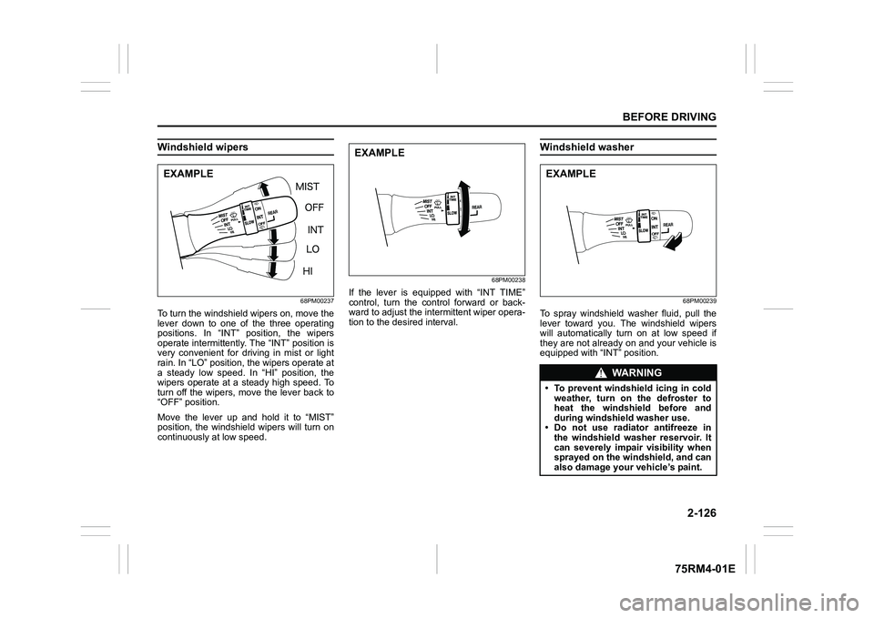
68PM00237
To turn the windshield wipers on, move the
lever down to one of the three operating
positions. In “INT” position, the wipers
operate intermittently. The “INT” position is
very convenient for driving in mist or light
rain. In “LO” position, the wipers operate at
a steady low speed. In “HI” position, the
wipers operate at a steady high speed. To
turn off the wipers, move the lever back to
“OFF” position.
Move the lever up and hold it to “MIST”
position, the windshield wipers will turn on
continuously at low speed.
68PM00238
If the lever is equipped with “INT TIME”
control, turn the control forward or back-
ward to adjust the int ermittent wiper opera-
tion to the desired interval.
Windshield washer
68PM00239
To spray windshield washer fluid, pull the
lever toward you. The windshield wipers
will automatically turn on at low speed if
they are not already on and your vehicle is
equipped with “INT” position.
EXAMPLE
EXAMPLE
WA R N I N G
• To prevent windshield icing in cold weather, turn on the defroster to
heat the windshield before and
during windshield washer use.
• Do not use radiator antifreeze in
the windshield washer reservoir. It
can severely impair visibility when
sprayed on the windshield, and can
also damage your vehicle’s paint.EXAMPLE
Page 163 of 505
3-10
OPERATING YOUR VEHICLE
75RM4-01E
NOTE:
• Even when the remote controller is in theinterior workable area, if it is in any of the
following conditions, you may not be
able to start the engine or select the igni-
tion modes, and the REMOTE CON-
TROLLER OUTSIDE warning may be
given.
– The remote controller’s battery is low.
– The remote controller is affected by strong radio signals or noise.
– The remote controller is in contact with
or covered by a metallic object.
– The remote controller is in stowage such as the glove box or a door
pocket.
– The remote controller is in the sun
visor pocket or on the floor.
• Even when the remote controller is out- side the interior workable area, if it is in
any of the following conditions, you may
be able to start the engine or select the
ignition mode. The REMOTE CON-
TROLLER OUTSIDE warning may not
be given at that time.
– The remote controller is outside the
vehicle but very close to a door.
– The remote controller is on the instru-
ment panel.
Parking brake lever
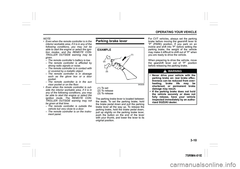
54G039
(1) To set
(2) To release
(3) To release
The parking brake lever is located between
the seats. To set the parking brake, hold
the brake pedal down and pull the parking
brake lever all the way up. To release the
parking brake, hold the brake pedal down,
pull up slightly on the parking brake lever,
push the button on the end of the lever
with your thumb, and lower the lever to its
original position. For CVT vehicles, always set the parking
brake before moving the gearshift lever to
“P” (PARK) position. If you park on an
incline and shift into “P” before setting the
parking brake, the weight of the vehicle
may make it difficult to shift out of “P” when
you are ready to drive the vehicle.
When preparing to drive the vehicle, move
the gearshift lever out of “P” position
before releasing the parking brake.
(2)
(3) (1)
EXAMPLE
WA R N I N G
• Never drive your vehicle with the
parking brake on: rear brake effec-
tiveness can be reduced from over-
heating, brake life may be
shortened, or permanent brake
damage may result.
• If the parking brake does not hold the vehicle securely or does not
fully release, have your vehicle
inspected immediately by an autho-
rized SUZUKI dealer.
Page 175 of 505
3-22
OPERATING YOUR VEHICLE
75RM4-01E
Manual mode (models with manual
mode)
The CVT can shift gears automatically.
When using the manual mode, you can
shift gears in the same manner as conven-
tional manual transaxle.
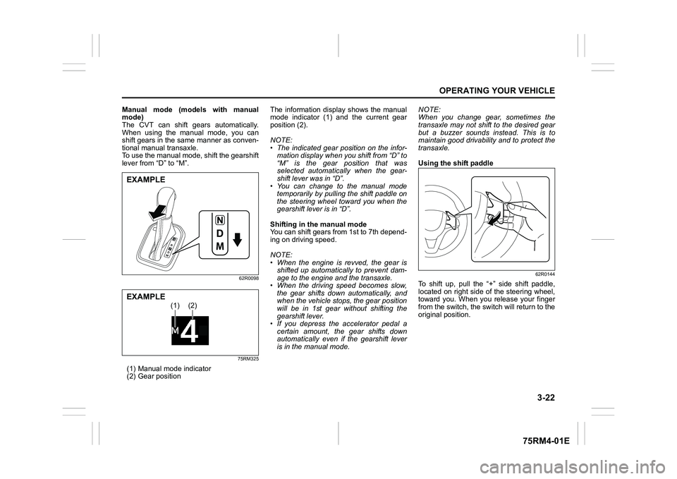
To use the manual mode, shift the gearshift
lever from “D” to “M”.
62R0098
75RM325
(1) Manual mode indicator
(2) Gear position The information display shows the manual
mode indicator (1) and the current gear
position (2).
NOTE:
• The indicated gear position on the infor-
mation display when you shift from “D” to
“M” is the gear position that was
selected automatically when the gear-
shift lever was in “D”.
• You can change to the manual mode temporarily by pulling the shift paddle on
the steering wheel toward you when the
gearshift lever is in “D”.
Shifting in the manual mode
You can shift gears from 1st to 7th depend-
ing on driving speed.
NOTE:
• When the engine is revved, the gear is shifted up automatically to prevent dam-
age to the engine and the transaxle.
• When the driving speed becomes slow, the gear shifts down automatically, and
when the vehicle stops, the gear position
will be in 1st gear without shifting the
gearshift lever.
• If you depress the accelerator pedal a
certain amount, the gear shifts down
automatically even if the gearshift lever
is in the manual mode. NOTE:
When you change gear, sometimes the
transaxle may not shift to the desired gear
but a buzzer sounds instead. This is to
maintain good drivability and to protect the
transaxle.
Using the shift paddle
62R0144
To shift up, pull the “+” side shift paddle,
located on right side of the steering wheel,
toward you. When you release your finger
from the switch, the switch will return to the
original position.
EXAMPLE
(1)
(2)
EXAMPLE
Page 176 of 505
3-23OPERATING YOUR VEHICLE
75RM4-01E
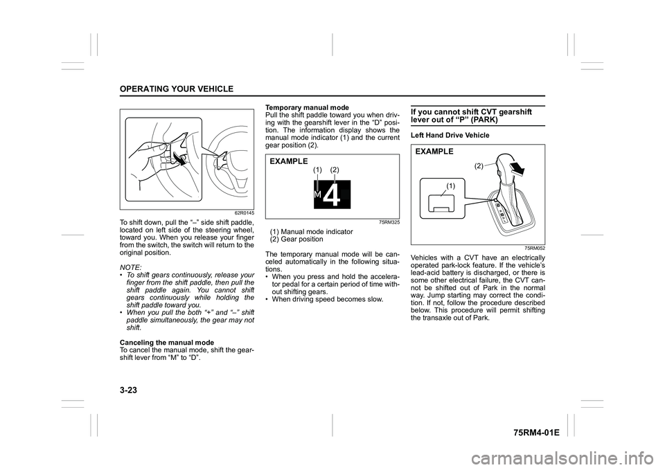
62R0145
To shift down, pull the “–” side shift paddle,
located on left side of the steering wheel,
toward you. When you release your finger
from the switch, the switch will return to the
original position.
NOTE:
• To shift gears continuously, release yourfinger from the shift paddle, then pull the
shift paddle again. You cannot shift
gears continuously while holding the
shift paddle toward you.
• When you pull the both “+” and “ –” shift
paddle simultaneously, the gear may not
shift.
Canceling the manual mode
To cancel the manual mode, shift the gear-
shift lever from “M” to “D”. Temporary manual mode
Pull the shift paddle toward you when driv-
ing with the gearshift lever in the “D” posi-
tion. The information display shows the
manual mode indicator (1) and the current
gear position (2).
75RM325
(1) Manual mode indicator
(2) Gear position
The temporary manual mode will be can-
celed automatically in the following situa-
tions.
• When you press and hold the accelera- tor pedal for a certain period of time with-
out shifting gears.
• When driving spee d becomes slow.
If you cannot shift CVT gearshift lever out of “P” (PARK)Left Hand Drive Vehicle
75RM052
Vehicles with a CVT have an electrically
operated park-lock feat ure. If the vehicle’s
lead-acid battery is discharged, or there is
some other electrical failure, the CVT can-
not be shifted out of Park in the normal
way. Jump starting may correct the condi-
tion. If not, follow the procedure described
below. This procedure will permit shifting
the transaxle out of Park.
(1)
(2)
EXAMPLE
(1)
(2)
EXAMPLE
Page 196 of 505
3-43OPERATING YOUR VEHICLE
75RM4-01E
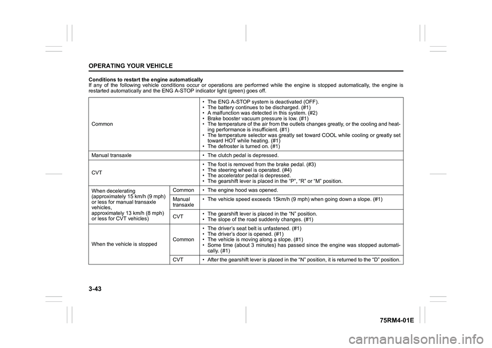
Conditions to restart the engine automatically
If any of the following vehicle conditions occur or operations are performed while the engine is stopped automatically, the en gine is
restarted automatically and the ENG A-STOP i ndicator light (green) goes off.
Common • The ENG A-STOP system is deactivated (OFF).
• The battery continues to be discharged. (#1)
• A malfunction was detect
ed in this system. (#2)
• Brake booster vacuum pressure is low. (#1)
• The temperature of the air from the outlets changes greatly, o r the cooling and heat-
ing performance is insufficient. (#1)
• The temperature selector was greatly set toward COOL while coo ling or greatly set
toward HOT while heating. (#1)
• The defroster is turned on. (#1)
Manual transaxle • The cl utch pedal is depressed.
CVT • The foot is removed from the brake pedal. (#3)
• The steering wheel is operated. (#4)
• The accelerator pedal is depressed.
• The gearshift lever is placed
in the “P”, “R” or “M” position.
When decelerating
(approximately 15 km/h (9 mph)
or less for manual transaxle
vehicles,
approximately 13 km/h (8 mph)
or less for CVT vehicles) Common • The engine hood was opened.
Manual
transaxle
• The vehicle speed exceeds 15km/
h (9 mph) when going down a slope. (#1)
CVT • The gearshift lever is placed in the “N” position.
• The slope of the road
suddenly changes. (#1)
When the vehicle is stopped Common• The driver’s seat
belt is unfastened. (#1)
• The driver’s door is opened. (#1)
• The vehicle is movi ng along a slope. (#1)
• Some time (about 3 minutes) has passed since the engine was st opped automati-
cally. (#1)
CVT • After the gearshift lever is placed in the “N” position, it is returned to the “D” position.