turn signal SUZUKI IGNIS 2022 User Guide
[x] Cancel search | Manufacturer: SUZUKI, Model Year: 2022, Model line: IGNIS, Model: SUZUKI IGNIS 2022Pages: 505, PDF Size: 8.36 MB
Page 146 of 505
2-123BEFORE DRIVING
75RM4-01E
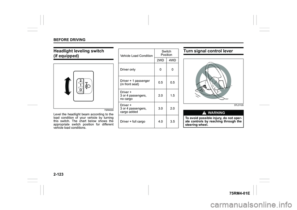
Headlight leveling switch (if equipped)
75RM008
Level the headlight beam according to the
load condition of your vehicle by turning
this switch. The chart below shows the
appropriate switch position for different
vehicle load conditions.
Turn signal control lever
57L21128
Vehicle Load ConditionSwitch
Position
2WD 4WD
Driver only 0 0
Driver + 1 passenger
(in front seat) 0.5 0.5
Driver +
3 or 4 passengers,
no cargo 2.0 1.5
Driver +
3 or 4 passengers,
cargo added 3.0 2.0
Driver + full cargo 4.0 3.5
WA R N I N G
To avoid possible injury, do not oper-
ate controls by reaching through the
steering wheel.
Page 147 of 505

2-124
BEFORE DRIVING
75RM4-01E
Turn signal operationWith the ignition switch in “ON” position or
the ignition mode ON, move the lever
upward or downward to activate the right
or left turn signals.
Normal turn signal
68PM00234
Move the lever all the way upward or
downward to signal. When the turn is com-
pleted, the signal will cancel and the lever
will return to its normal position.Lane change signal
68PM00235
Move the lever partway upward or down-
ward to turn right or left and hold the lever
in the moved position.
• The turn signal and its indicator flash
while the lever is held at the moved posi-
tion.
The turn signal and its indicator flash 3
times even if you return the lever immedi-
ately after moving it.
NOTE:
The turn signal and its indicator can be set
whether they flash 3 times after the turn
signal lever is returned via the information
display. Refer to “Information display” in
this section. NOTE:
You can customize the setting for the num-
ber of flashing times of the turn signal and
its indicator (1 to 4 times). Please ask an
authorized SUZUKI dealer for the customi-
zation.
EXAMPLE
EXAMPLE
Page 148 of 505
2-125BEFORE DRIVING
75RM4-01E
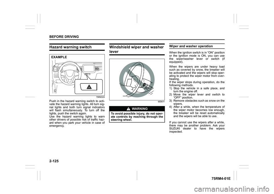
Hazard warning switch
75RM324
Push in the hazard warning switch to acti-
vate the hazard warning lights. All turn sig-
nal lights and both turn signal indicators
will flash simultaneously. To turn off the
lights, push the switch again.
Use the hazard warning lights to warn
other drivers of possible risk of traffic haz-
ard when you park your vehicle in case of
emergency.
Windshield wiper and washer lever
65D611
Wiper and washer operationWhen the ignition switch is in “ON” position
or the ignition mode is ON, you can use
the wiper/washer lever or switch (if
equipped).
When the wipers are under heavy load
such as covered by snow, the breaker will
be activated and the wipers will stop oper-
ating to protect the wiper motor from over-
heating.
If the wiper stops during operation, do the
following methods.
1) Stop the vehicle in a safe place, andturn the engine off.
2) Move the wiper lever and switch to “OFF” position.
3) Remove obstacles such as snow on the wipers.
4) After a while, when the temperature of
the wiper motor becomes low enough,
the breaker will be reset automatically
and the wipers will be able to use.
If you cannot use the wipers after a while,
there may be another problem. Ask your
SUZUKI dealer to have the wipers
inspected.
EXAMPLE
WA R N I N G
To avoid possible injury, do not oper-
ate controls by reaching through the
steering wheel.
Page 155 of 505
3-2
OPERATING YOUR VEHICLE
75RM4-01E
NOTE:
It is normal for water to drip from the air
conditioning system after use.
4) Check that the hood is fully closed andlatched.
5) Check the headlights, turn signal lights, brake lights and horn for proper opera-
tion.
6) Adjust the seat and head restraint.
7) Check the brake pedal and the parking brake lever.
8) Adjust the mirrors.
9) Check that you and all passengers have properly fastened your seat belts.
10)Check that all warning lights come on as the ignition switch is turned to “ON”
position or the engine switch is pressed
to change the ignition mode to ON.
11)Check all gauges.
12)Check that the brake system warning light turns off when the parking brake is
released.
Once a week, or each time you fill your fuel
tank, perform the following under-hood
checks:
1) Engine oil level
2) Coolant level
3) Brake fluid level
4) Lead-acid battery solution level
5) Windshield washer fluid level
6) Hood latch operation Pull the hood release handle inside the
vehicle. Check that you cannot open the hood all the way without releasing
the secondary latch. Close the hood
securely after checking for proper latch
operation. See the item “All latches,
hinges and locks” of “Chassis, body
and others” in “Maintenance schedule”
in the “INSPECTION AND MAINTE-
NANCE” section for lubrication sched-
ule.
Once a month, or each time you fill your
fuel tank, check the tire pressure using a
tire pressure gauge. Also check the tire
pressure of the spare tire.
Engine oil consumptionIt is normal for the engine to consume
some engine oil during normal vehicle
operation.
The amount of engine oil consumption
depends on viscosity and quality of the oil
and your driving conditions.
More oil is consumed during high-speed
driving and when there is frequent acceler-
ation and deceleration. Under high loads,
your engine also will consume more oil.
A new engine also consumes more oil,
since its pistons, piston rings and cylinder
walls have not yet become conditioned.
New engines reach the normal level of oil
consumption only after approximately
5000 km (3000 miles) driving.
Oil consumption:
Max. 1.0 L per 1000 km
(1 Qt. per 600 miles)
When judging the amount of oil consump-
tion, note that the oil may become diluted
and it is difficult to judge the accurate oil
level.
As an example, if a vehicle is used for
repeated short trips, and consumes a nor-
mal amount of oil, the dipstick may not
show any drop in the oil level at all, even
after 1000 km (600 miles) or more of driv-
ing. This is because the oil gradually
becomes diluted with fuel or moisture,
WA R N I N G
Check that the hood is fully closed
and latched before d riving. If it is not,
it can fly up unexpectedly during
driving, obstructing your view and
resulting in an accident.
Page 159 of 505
3-6
OPERATING YOUR VEHICLE
75RM4-01E
CVT – Provided you have the keyless
push start system remote controller with
you, the engine automatically starts when
you press the engine switch to select this
ignition mode after placing the gearshift
lever in the “P” position and depressing the
brake pedal. (If you need to re-start the
engine while the vehicle is moving, shift
into “N”.)
NOTE:
You do not need to keep the engine switch
pressed to start the engine.
NOTE:
In the presence of strong radio signals or
noise, you may not be able to change the
ignition mode to ACC or ON or to start the
engine using the engine switch. In this
case, the information display in the instru-
ment cluster will show the following mes-
sage: KEY FOB NOT DETECTED.
Unreleased steering lock warningIf the steering lock remains engaged when
you press the engine switch to change the
ignition mode to ON, the information dis-
play in the instrument cluster shows the
message: “TRN. STEERING WHEEL TO
RELEASE LOCK”. Refer to “Information
display” in the “BEFORE DRIVING” sec-
tion for details.
NOTE:
The steering lock may not be released and
the immobilizer/keyless push start system
warning light turns on if some load is acting
on the steering wheel . If this happens, turn
the steering wheel to the right or left to
relieve it from the load before you press
the engine switch again to change to the
desired ignition mode.
Keyless push start system (if equipped)Provided the keyless push start system
remote controller is within the interior work-
able area (refer to the related explanation
in this section), you can use the engine
switch for starting the engine and selecting
an ignition mode (ACC or ON). In addition,
the following functions can be used:
• Keyless entry function. Refer to “Keyless push start system r emote controller /
keyless entry system transmitter” in the
“BEFORE DRIVING” se ction for details.
• Locking and unlocking doors (including the tailgate) using a request switch.
Refer to “Keyless push start system
remote controller / keyless entry system
transmitter” in the “BEFORE DRIVING”
section for details.
• Immobilizer (anti-thef t) function. Refer to
“Immobilizer syste m” in the “BEFORE
DRIVING” section for details.
NOTICE
Do not leave the engine switch in
ACC or ON mode when the engine is
not running. Avoid using the radio or
other electric accessories for a long
time when the engine switch is in
ACC or ON mode when the engine is
not running, other wise the lead-acid
battery may discharge.
Page 188 of 505
3-35OPERATING YOUR VEHICLE
75RM4-01E
ENG A-STOP system
(engine auto stop start system) (if equipped)The ENG A-STOP system (engine auto
stop start system) automatically stops and
restarts the engine when decelerating
before stopping and when the vehicle is
stopped, such as at a traffic signal, in order
to reduce exhaust gases, fuel consumption
and engine noise.
• This system automatically stops the engine under certain conditions. When
the vehicle will be stopped for a long
time or when you will leave the vehicle
unattended, set the parking brake firmly,
and then turn the ignition switch or press
the engine switch to stop the engine.
• If certain conditions are met, the engine is stopped automatically when decelerat-
ing (approximately 15 km/h (9 mph) or
less for manual transaxle vehicles,
approximately 13 km/h (8 mph) or less
for CVT vehicles) before stopping. How-
ever, the engine will not be stopped
automatically during deceleration until
confirmation of the system function is fin-
ished. NOTE:
If your vehicle is equipped with the auto-
matic heating and ai
r conditioning system,
you can change the automatic engine stop
condition via the information display. Refer
to “Setting mode” in “Information display
(instrument cluster with tachometer)” in the
“BEFORE DRIVING” section.
75RM054
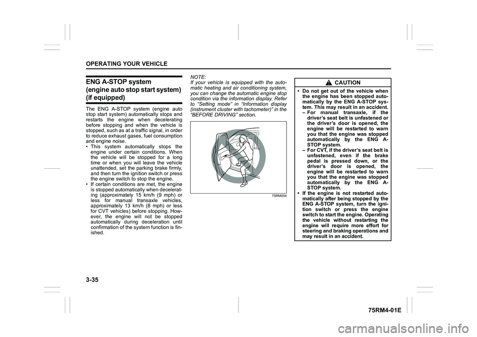
CAUTION
• Do not get out of the vehicle when the engine has been stopped auto-
matically by the ENG A-STOP sys-
tem. This may result in an accident.
– For manual transaxle, if the
driver’s seat belt is unfastened or
the driver’s door is opened, the
engine will be restarted to warn
you that the engine was stopped
automatically by the ENG A-
STOP system.
– For CVT, if the driver’s seat belt is unfastened, even if the brake
pedal is pressed down, or the
driver’s door is opened, the
engine will be restarted to warn
you that the engine was stopped
automatically by the ENG A-
STOP system.
• If the engine is not restarted auto- matically after being stopped by the
ENG A-STOP system, turn the igni-
tion switch or press the engine
switch to start the engine. Operating
the vehicle without restarting the
engine will require more effort for
steering and braking operations and
may result in an accident.
Page 194 of 505
3-41OPERATING YOUR VEHICLE
75RM4-01E
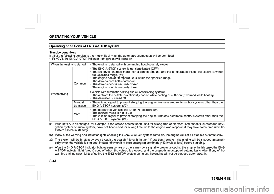
Operating conditions of ENG A-STOP systemStandby conditions
If all of the following conditions are met while driving, the automatic engine stop will be permitted.
• For CVT, the ENG A-STOP indicator light (green) will come on.
#1: If the battery is discharged, for example, if the vehicle has not been used for a long time or electrical components, such as the navi-
gation system or audio system, have not been used for a long ti me while the engine was stopped, it may take some time until th e
system can be in standby.
#2: If any of the warning and indi cator lights affecting the ENG A-STOP system come on, the e ngine will not be stopped automati cally.
#3: The system will be in standby even though the gearshift leve r is in the “N” position, however, the engine will be stopped automati-
cally when the vehicl e is stopped, instead of when it is decelerating (approximately 13 km/ h or less) before stopping.
#4: After the ENG A-STOP indicator light (green) comes on, there may be a signal to prevent stopping the engine. In this case, the ENG
A-STOP indicator light (green) goes off when the vehicle is sto pped, and the engine is not stopped automatically. Also, if any of the
warning and indi cator lights affecting the ENG A-STOP system co me on, the engine will not be stopped automatically.
When the engine is started • The
engine is started with the engine hood securely closed.
When driving Common• The ENG A-STOP system is
not deactivated (OFF).
• The battery is charged more than a certain amount, and the tem perature inside the battery is within
the specified range. (#1)
• The engine coolant temperature i s within the specified range.
• The driver’s seat belt is fastened.
• The driver’s door is securely closed.
• The engine hood is s ecurely closed.
• The air from the outlets is su fficiently cooled while cooling or sufficiently warmed while heating.
• The defroster is turned off.
Manual
transaxle • There is no signal to prevent stopping the engine from any ele
ctronic control systems other than the
ENG A-STOP system. (#2)
CVT • The gearshift lever is in the
“D” or “N” position. (#3)
• The manual mode is not in use.
• There is no signal to prevent stopping the engine from any ele ctronic control systems other than the
ENG A-STOP system. (#4)
Page 212 of 505
3-59OPERATING YOUR VEHICLE
75RM4-01E
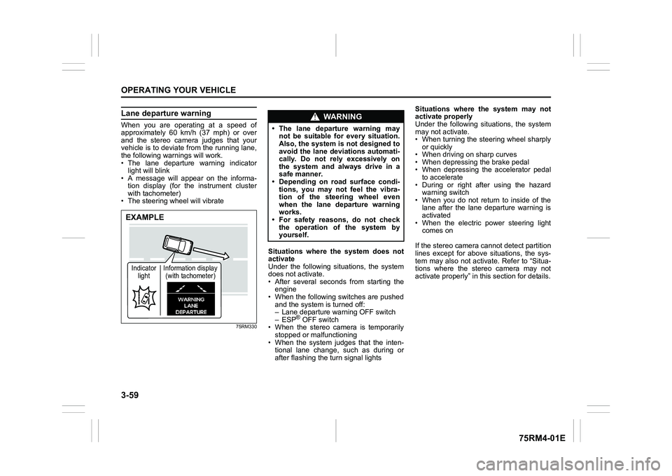
Lane departure warningWhen you are operating at a speed of
approximately 60 km/h (37 mph) or over
and the stereo camera judges that your
vehicle is to deviate from the running lane,
the following warnings will work.
• The lane departure warning indicatorlight will blink
• A message will appear on the informa-
tion display (for the instrument cluster
with tachometer)
• The steering wheel will vibrate
75RM330
Situations where the system does not
activate
Under the following situations, the system
does not activate.
• After several seconds from starting the engine
• When the following switches are pushed and the system is turned off:
– Lane departure warning OFF switch
– ESP
® OFF switch
• When the stereo camera is temporarily stopped or malfunctioning
• When the system judges that the inten- tional lane change, such as during or
after flashing the turn signal lights Situations where the system may not
activate properly
Under the following situations, the system
may not activate.
• When turning the steering wheel sharply
or quickly
• When driving on sharp curves
• When depressing the brake pedal
• When depressing the accelerator pedal to accelerate
• During or right after using the hazard warning switch
• When you do not return to inside of the lane after the lane departure warning is
activated
• When the electric power steering light comes on
If the stereo camera cannot detect partition
lines except for above situations, the sys-
tem may also not activ ate. Refer to “Situa-
tions where the stereo camera may not
activate properly” in this section for details.
EXAMPLEIndicator light Information display
(with tachometer)
WA R N I N G
• The lane departure warning may not be suitable for every situation.
Also, the system is not designed to
avoid the lane deviations automati-
cally. Do not rely excessively on
the system and always drive in a
safe manner.
• Depending on road surface condi-
tions, you may not feel the vibra-
tion of the steering wheel even
when the lane departure warning
works.
• For safety reasons, do not check
the operation of the system by
yourself.
Page 224 of 505
3-71OPERATING YOUR VEHICLE
75RM4-01E
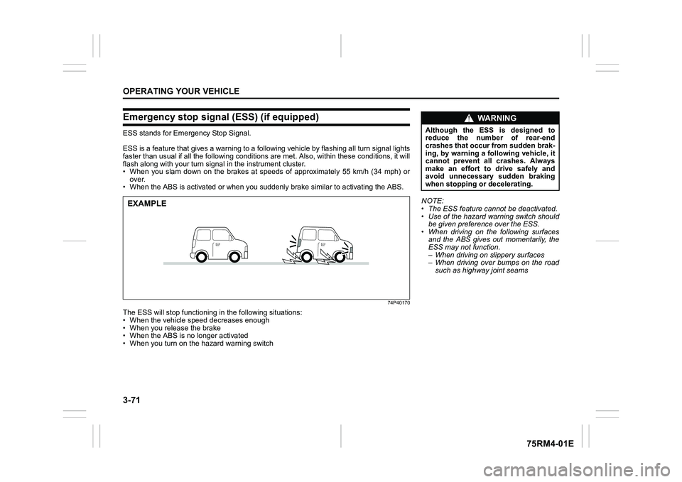
Emergency stop signal (ESS) (if equipped)ESS stands for Emergency Stop Signal.
ESS is a feature that gives a war ning to a following vehicle by flashing all turn signal lights
faster than usual if all the following conditions are met. Also , within these conditions, it will
flash along with your turn signal in the instrument cluster.
• When you slam down on the brakes at speeds of approximately 55 km/h (34 mph) or
over.
• When the ABS is activated or when you suddenly brake similar to activating the ABS.
74P40170
The ESS will stop functioning in the following situations:
• When the vehicle speed decreases enough
• When you release the brake
• When the ABS is no longer activated
• When you turn on the hazard warning switchEXAMPLE
NOTE:
• The ESS feature cannot be deactivated.
• Use of the hazard warning switch should
be given preference over the ESS.
• When driving on the following surfaces and the ABS gives out momentarily, the
ESS may not function.
– When driving on slippery surfaces
– When driving over bumps on the road
such as highway joint seams
WA R N I N G
Although the ESS is designed to
reduce the number of rear-end
crashes that occur from sudden brak-
ing, by warning a following vehicle, it
cannot prevent all crashes. Always
make an effort to drive safely and
avoid unnecessary sudden braking
when stopping or decelerating.
Page 241 of 505
3-88
OPERATING YOUR VEHICLE
75RM4-01E
61MM0A198
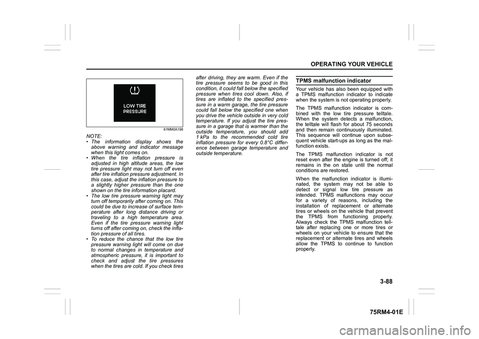
NOTE:
• The information display shows theabove warning and indicator message
when this light comes on.
• When the tire inflation pressure is
adjusted in high altitude areas, the low
tire pressure light may not turn off even
after tire inflation pressure adjustment. In
this case, adjust the inflation pressure to
a slightly higher pressure than the one
shown on the tire information placard.
• The low tire pressure warning light may turn off temporarily after coming on. This
could be due to increase of surface tem-
perature after long distance driving or
traveling to a high temperature area.
Even if the tire pressure warning light
turns off after coming on, check the infla-
tion pressure of all tires.
• To reduce the chance that the low tire pressure warning light will come on due
to normal changes in temperature and
atmospheric pressure, it is important to
check and adjust the tire pressures
when the tires are cold. If you check tires after driving, they are warm. Even if the
tire pressure seems to be good in this
condition, it could fall below the specified
pressure when tires cool down. Also, if
tires are inflated to the specified pres-
sure in a warm garage, the tire pressure
could fall below the specified one when
you drive the vehicle outside in very cold
temperature. If you adjust the tire pres-
sure in a garage that is warmer than the
outside temperature, you should add
1 kPa to the recommended cold tire
inflation pressure for every 0.8°C differ-
ence between garage temperature and
outside temperature.
TPMS malfunction indicatorYour vehicle has also been equipped with
a TPMS malfunction indicator to indicate
when the system is not operating properly.
The TPMS malfunction indicator is com-
bined with the low tire pressure telltale.
When the system detects a malfunction,
the telltale will flash for about 75 seconds
and then remain continuously illuminated.
This sequence will continue upon subse-
quent vehicle start-ups as long as the mal-
function exists.
The TPMS malfunction indicator is not
reset even after the engine is turned off; it
remains in the on state until the normal
conditions are restored.
When the malfunction indicator is illumi-
nated, the system may not be able to
detect or signal low tire pressure as
intended. TPMS malfunctions may occur
for a variety of reasons, including the
installation of replacement or alternate
tires or wheels on the vehicle that prevent
the TPMS from functioning properly.
Always check the TPMS malfunction tell-
tale after replacing one or more tires or
wheels on your vehicle to ensure that the
replacement or alternate tires and wheels
allow the TPMS to continue to function
properly.