release SUZUKI IGNIS 2022 Workshop Manual
[x] Cancel search | Manufacturer: SUZUKI, Model Year: 2022, Model line: IGNIS, Model: SUZUKI IGNIS 2022Pages: 505, PDF Size: 8.36 MB
Page 379 of 505
7-30
INSPECTION AND MAINTENANCE
75RM4-01E
81P60040
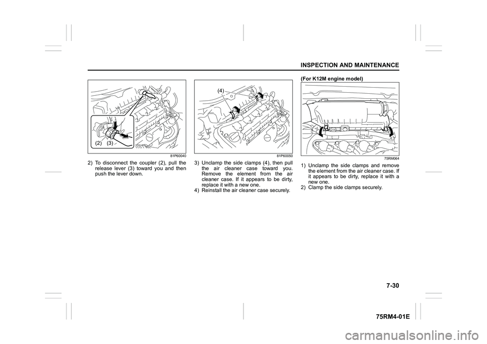
2) To disconnect the coupler (2), pull therelease lever (3) toward you and then
push the lever down.
81P60050
3) Unclamp the side clamps (4), then pullthe air cleaner case toward you.
Remove the element from the air
cleaner case. If it appears to be dirty,
replace it with a new one.
4) Reinstall the air cleaner case securely. (For K12M engine model)
75RM064
1) Unclamp the side clamps and remove
the element from the air cleaner case. If
it appears to be dirty, replace it with a
new one.
2) Clamp the side clamps securely.
(2) (3)
(4)
Page 380 of 505
7-31INSPECTION AND MAINTENANCE
75RM4-01E
Spark plugsSpark plug replacement and inspec-tion(For K12C engine model)
81PN235
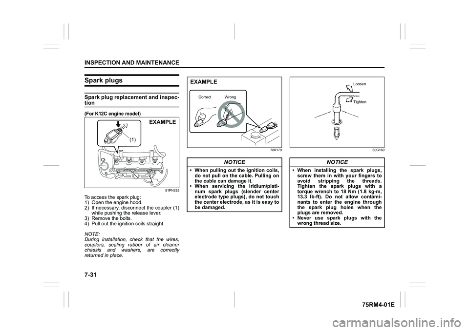
To access the spark plug:
1) Open the engine hood.
2) If necessary, disconnect the coupler (1)while pushing the release lever.
3) Remove the bolts.
4) Pull out the ignition coils straight.
NOTE:
During installation, check that the wires,
couplers, sealing rubber of air cleaner
chassis and washers, are correctly
returned in place.
78K179 60G160
(1)
EXAMPLE
NOTICE
• When pulling out the ignition coils,
do not pull on the cable. Pulling on
the cable can damage it.
• When servicing the iridium/plati-
num spark plugs (slender center
electrode type plu gs), do not touch
the center electrode, as it is easy to
be damaged.EXAMPLE
Correct Wrong
NOTICE
• When installing the spark plugs,
screw them in with your fingers to
avoid stripping the threads.
Tighten the spark plugs with a
torque wrench to 18 Nm (1.8 kg-m,
13.3 lb-ft). Do not allow contami-
nants to enter the engine through
the spark plug holes when the
plugs are removed.
• Never use spark plugs with the
wrong thread size.
Loosen
Tighten
Page 387 of 505
7-38
INSPECTION AND MAINTENANCE
75RM4-01E
Parking brake
54G109
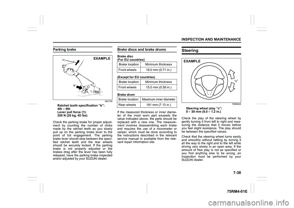
Ratchet tooth specification “b”:
4th – 9th
Lever pull force (1):
200 N (20 kg, 45 lbs)
Check the parking brake for proper adjust-
ment by counting the number of clicks
made by the ratchet teeth as you slowly
pull up on the parking brake lever to the
point of full engagement. The parking
brake lever should stop between the speci-
fied ratchet teeth and the rear wheels
should be securely locked. If the parking
brake is not properly adjusted or the
brakes drag after the lever has been fully
released, have the park ing brake inspected
and/or adjusted by your SUZUKI dealer.
Brake discs and brake drumsBrake disc
(For EU countries)
(Except for EU countries)
Brake drum
If the measured thickness or inner diame-
ter of the most worn part exceeds the
value indicated above, the parts should be
replaced with a new one. The measure-
ment involves disassembling each brake
and requires the use of a micrometer or
caliper, which must be done according to
the instructions described in the relevant
service manual or available from the rele-
vant repair information site.
Steering
75RM035
Steering wheel play “c”:
0 – 30 mm (0.0 – 1.2 in.)
Check the play of the steering wheel by
gently turning it from left to right and mea-
suring the distance that it moves before
you feel slight resistance. The play should
be between the specified values.
Check that the steering wheel turns easily
and smoothly without r attling by turning it
all the way to the right and to the left while
driving very slowly in an open area. If the
amount of free play is not as specified or
you find anything else to be wrong, an
inspection must be performed by your
SUZUKI dealer.
EXAMPLE
Brake location Minimum thickness
Front wheels 18.0 mm (0.71 in.)
Brake location Minimum thickness
Front wheels 15.0 mm (0.59 in.)
Brake location Maximum inner diameter
Rear wheels 181 mm (7.13 in.)
“c”
EXAMPLE
Page 400 of 505
7-51INSPECTION AND MAINTENANCE
75RM4-01E
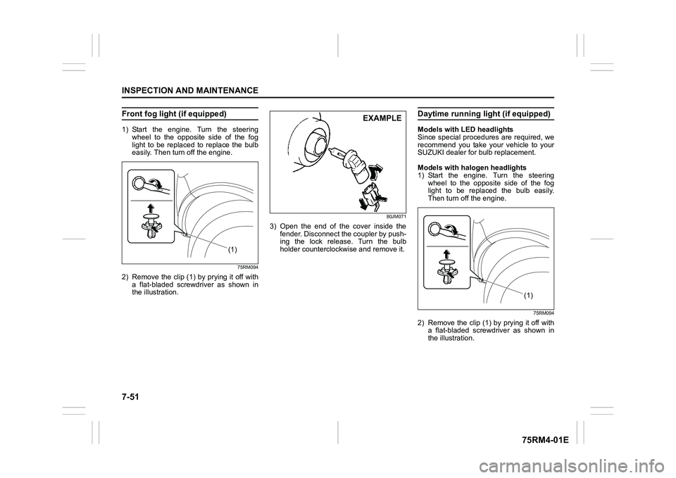
Front fog light (if equipped)1) Start the engine. Turn the steeringwheel to the opposite side of the fog
light to be replaced to replace the bulb
easily. Then turn off the engine.
75RM094
2) Remove the clip (1) by prying it off witha flat-bladed screwdriver as shown in
the illustration.
80JM071
3) Open the end of the cover inside thefender. Disconnect the coupler by push-
ing the lock release. Turn the bulb
holder counterclockwise and remove it.
Daytime running light (if equipped)Models with LED headlights
Since special procedures are required, we
recommend you take your vehicle to your
SUZUKI dealer for bulb replacement.
Models with halogen headlights
1) Start the engine. Turn the steering
wheel to the opposite side of the fog
light to be replaced the bulb easily.
Then turn off the engine.
75RM094
2) Remove the clip (1) by prying it off witha flat-bladed screwdriver as shown in
the illustration.
(1)
EXAMPLE
(1F
Page 401 of 505
7-52
INSPECTION AND MAINTENANCE
75RM4-01E
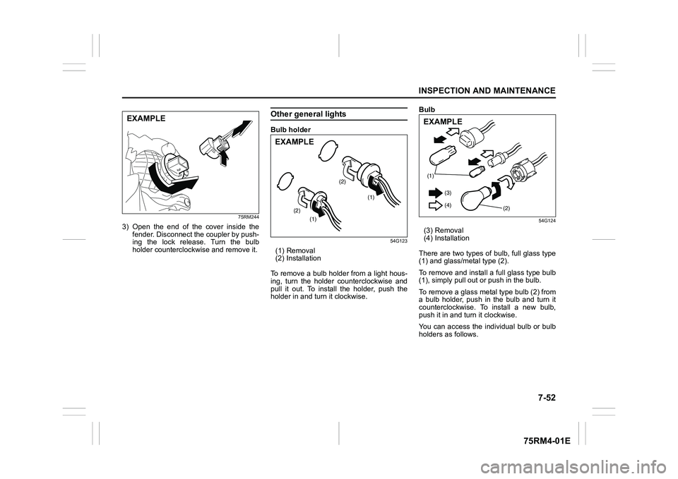
75RM244
3) Open the end of the cover inside thefender. Disconnect the coupler by push-
ing the lock release. Turn the bulb
holder counterclockwise and remove it.
Other general lightsBulb holder
54G123
(1) Removal
(2) Installation
To remove a bulb holder from a light hous-
ing, turn the holder counterclockwise and
pull it out. To install the holder, push the
holder in and turn it clockwise. Bulb
54G124
(3) Removal
(4) Installation
There are two types of bulb, full glass type
(1) and glass/metal type (2).
To remove and install a full glass type bulb
(1), simply pull out or push in the bulb.
To remove a glass metal type bulb (2) from
a bulb holder, push in the bulb and turn it
counterclockwise. To install a new bulb,
push it in and tu rn it clockwise.
You can access the individual bulb or bulb
holders as follows.
EXAMPLE
(1)
(1)
(2) (2)
EXAMPLE
(1)
(2)
(
3 )
(4)EXAMPLE
Page 403 of 505
7-54
INSPECTION AND MAINTENANCE
75RM4-01E
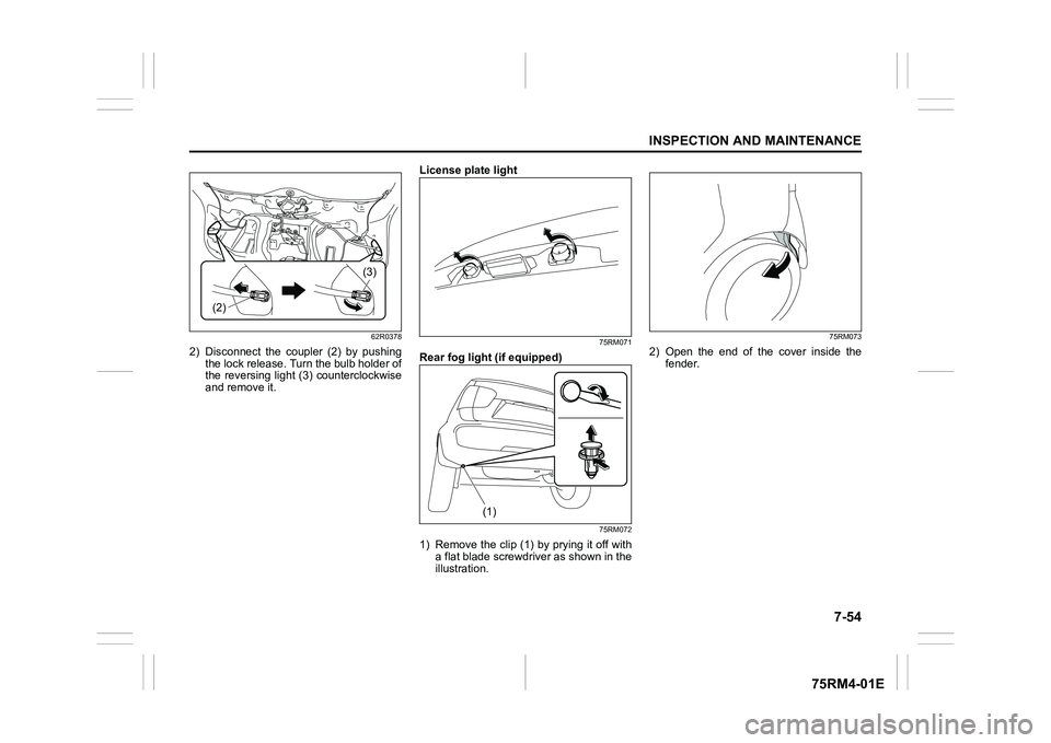
62R0378
2) Disconnect the coupler (2) by pushingthe lock release. Turn the bulb holder of
the reversing light (3) counterclockwise
and remove it. License plate light
75RM071
Rear fog light (if equipped)
75RM072
1) Remove the clip (1) by prying it off with
a flat blade screwdriver as shown in the
illustration.
75RM073
2) Open the end of the cover inside thefender.
(2)
(3)
(1)
Page 421 of 505
8-12
EMERGENCY SERVICE
75RM4-01E
2-wheel drive (2WD) CVTCVT vehicles may be towed using either of
the following methods.
1) From the front, with the front wheelslifted and the rear wheels on the
ground. Before towing, make sure that
the parking brak e is released.
2) From the rear, with the rear wheels
lifted and a dolly under the front wheels.
2-wheel drive (2WD) manual tran-saxle or Auto Gear ShiftManual transaxle vehicles or Auto Gear
Shift vehicles may be towed using either of
the following methods.
1) From the front, with the front wheelslifted and the rear wheels on the
ground. Before towing, check that the
parking brake is released.
2) From the rear, with the rear wheels
lifted and the front wheels on the
ground, provided the steering and
drivetrain are in operational condition.
Before towing, check that transaxle is in
neutral, the steering wheel is unlocked
(vehicle without keyl ess push start sys-
tem - the ignition key should be in
“ACC” position) (vehicle with keyless
push start system - the ignition mode is
ACC), and the steering wheel is
secured with a clamping device
designed for towing service.
4-wheel drive (4WD)Your vehicle should be towed under one of
the following conditions:
1) With all four wheels on a flat-bed truck.
2) With the front or rear wheels lifted and a dolly under the other wheels.
NOTICE
Towing your vehicle with the front
wheels on the ground can result in
damage to the CVT.
NOTICE
The steering column is not strong
enough to withstand shocks trans-
mitted from the fr ont wheels during
towing. Always unlock the steering
wheel before towing.
NOTICE
After shifting the Auto Gear Shift
gearshift lever to the “N” position,
always check the gear position indi-
cator in the instrument cluster shows
the “N” position to make sure that the
transaxle is disengaged.
If the transaxle cannot be put in neu-
tral, turn the key from the “LOCK” to
the “ON” position or press the engine
switch to change the ignition mode to
ON, and move the Auto Gear Shift
gearshift lever from “N” to “D”, “M”
or “R”, then back to “N” again. Then
turn the key from the “ON” to the
“LOCK” position or press the engine
switch to change the ignition mode to
LOCK (OFF). These procedures may
help put the transaxle in neutral. If
the transaxle still cannot be put in
neutral, you cannot tow the vehicle
without using a towing dolly.