Speed control SUZUKI IGNIS 2022 Owners Manual
[x] Cancel search | Manufacturer: SUZUKI, Model Year: 2022, Model line: IGNIS, Model: SUZUKI IGNIS 2022Pages: 505, PDF Size: 8.36 MB
Page 6 of 505
75RM4-01E
Vehicle Data RecordingsThere are certain components of your vehicle (the “Vehicle”) incorporating data storage modules or memories, which temporarily or per-
manently store the technical data below listed. These data are exclusively technical and serve for (i) identifying and correcting faults
occurred in the Vehicle and/or ( ii) optimizing functions of the Vehicle.Recorded data (the “Recorded Data”)• Malfunctions, faults, and erro rs in important system component s. (e.g. lights, brakes)
• Reactions of the Vehicle in cer tain situations (e.g. inflation of SRS air bags, activation of stability control system).
• Operating conditions of system components (e.g. filling levels).
• Status messages of the Vehicle and its individual components ( e.g. vehicle speed, acceleration, deceleration, lateral acceleration).
• Ambient conditions (e.g. outside temperature).
Recorded data vary depending on vehicle model or grade.
Page 16 of 505
ILLUSTRATED TABLE OF CONTENTS
75RM4-01E
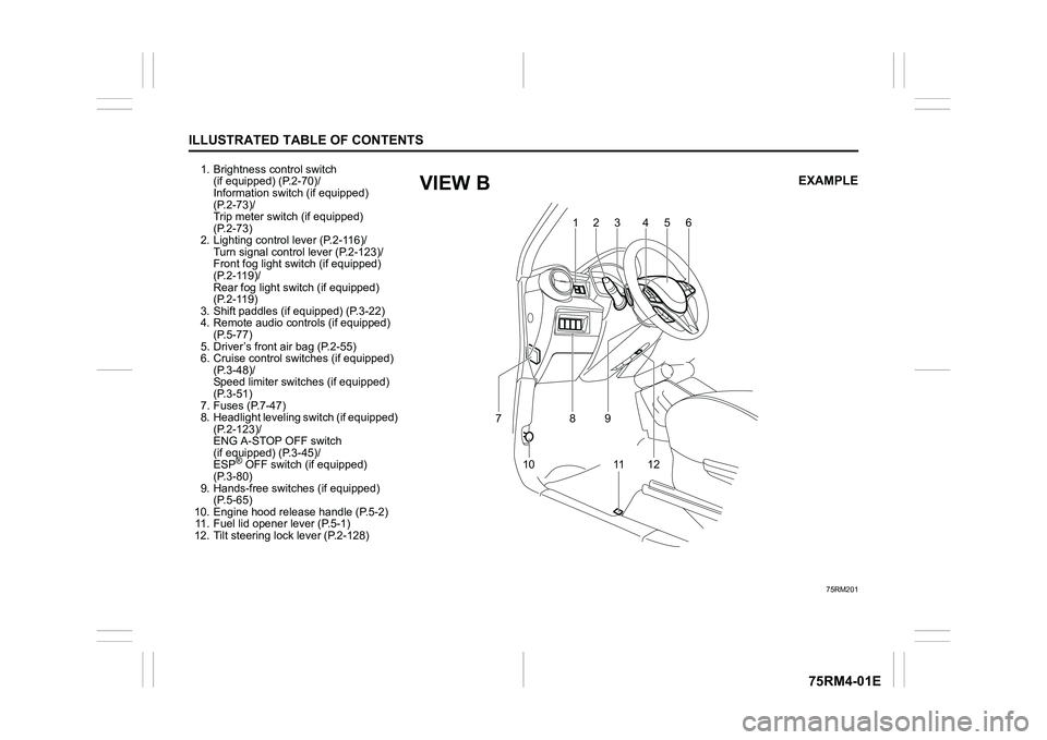
1. Brightness control switch (if equipped) (P.2-70)/
Information switch (if equipped)
(P.2-73)/
Trip meter switch (if equipped)
(P.2-73)
2. Lighting control lever (P.2-116)/
Turn signal control lever (P.2-123)/
Front fog light swit ch (if equipped)
(P.2-119)/
Rear fog light swit ch (if equipped)
(P.2-119)
3. Shift paddles (if equipped) (P.3-22)
4. Remote audio controls (if equipped) (P.5-77)
5. Driver’s front air bag (P.2-55)
6. Cruise control switches (if equipped) (P.3-48)/
Speed limiter switch es (if equipped)
(P.3-51)
7. Fuses (P.7-47)
8. Headlight leveling switch (if equipped) (P.2-123)/
ENG A-STOP OFF switch
(if equipped) (P.3-45)/
ESP
® OFF switch (if equipped)
(P.3-80)
9. Hands-free switc hes (if equipped)
(P.5-65)
10. Engine hood release handle (P.5-2) 11. Fuel lid opener lever (P.5-1)
12. Tilt steering lock lever (P.2-128)
75RM201
123 4 5
6
10 8
11 1 2
7
9
EXAMPLE
VIEW B
Page 23 of 505
BEFORE DRIVING
2
75RM4-01E
60G404
Keys ......................................................................................2-1
Door locks .................................................... ........................2-2
Keyless push start system remote controller /
Keyless entry system transmitte r (if equipped) ................2-7
Theft deterrent alarm system (if equipped) .................... ...2-16
Theft deterrent light (if equipped) ........................... ...........2-19
Windows ....................................................... ........................2-20
Mirrors ....................................................... ...........................2-23
Front seats ................................................... ........................2-27
Rear seats .................................................... .........................2-29
BEFORE DRIVINGSeat belts and child restraint systems ........................ ...... 2-33
Child restraint system f or countries applied for
UN Regulation No.16 ........................................... ................ 2-43
Supplemental restraint system (air bags) ...................... ... 2-54
Instrument cluster ............................................ ................... 2-68
Speedometer ................................................... .................... 2-69
Tachometer (if equipped) ...................................... ............. 2-69
Fuel gauge .................................................... ....................... 2-70
Brightness control ............................................ .................. 2-70
Information display
(instrument clus ter with tachometer) .......................... ...... 2-72
Information display
(instrument clus ter without tachometer) ....................... ... 2-93
Warning and indicator lights .................................. .......... 2-101
Lighting control lever ........................................ ............... 2-116
Headlight leveling switch (if equipped) ....................... .... 2-123
Turn signal control lever ..................................... ............. 2-123
Hazard warning switch ......................................... ............ 2-125
Windshield wiper and washer lever ............................. ... 2-125
Tilt steering lock lever ... ................................................... 2-128
Horn .......................................................... .......................... 2-128
Heated rear window switch /
heated outside rearview mirror switch (if equipped) ..... 2-129
Page 96 of 505
2-73BEFORE DRIVING
75RM4-01E
75RM183
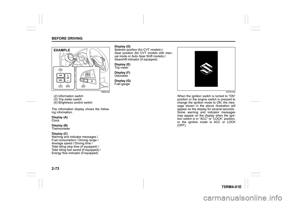
(2) Information switch
(3) Trip meter switch
(4) Brightness control switch
The information display shows the follow-
ing information.
Display (A)
Clock
Display (B)
Thermometer
Display (C)
Warning and indicator messages /
Fuel consumption / Driving range /
Average speed / Driving time /
Total idling stop time (if equipped) /
Total idling fuel saved (if equipped) /
Energy flow indicator (if equipped) Display (D)
Selector position (for CVT models) /
Gear position (for CVT models with man-
ual mode or Auto Gear Shift models) /
Gearshift indicator (if equipped)
Display (E)
Trip meter
Display (F)
Odometer
Display (G)
Fuel gauge
81P31150
When the ignition switch is turned to “ON”
position or the engine switch is pressed to
change the ignition mode to ON, the mes-
sage shown in the above illustration will
appear on the display
for several seconds.
Some warning and indicator messages
may appear on the display when the igni-
tion switch is in “ACC” or “LOCK” position,
or the ignition mode is ACC or LOCK
(OFF).
(4)
(2)(3)
(2)
EXAMPLE
Page 103 of 505
2-80
BEFORE DRIVING
75RM4-01E
NOTE:
• If you push and hold the informationswitch (2) to enter the setting mode
when the display (C) shows average fuel
consumption, average speed, driving
time, total idling stop time or total idling
fuel saved, the value will be reset simul-
taneously. If you do not want to reset the
value, push the information switch
quickly to switch the indication of the dis-
play.
• If you turn the ignition switch, press the
engine switch or start to move the vehi-
cle when the display is in the setting
mode, the setting mode will be canceled
automatically.
Distance unit (Odometer / trip meter distance unit setting)You can change the units in which odome-
ter / trip meter / driving range distance is
displayed.
Fuel economy
(Fuel consumption unit setting)
You can change the units that fuel con-
sumption is displayed in.
Language
You can change the language of the infor-
mation display.
Fuel reset
(Average fuel consumption reset setting)
You can change when the value of aver-
age fuel consumption is reset. Temperature (Tempera
ture unit setting)
You can change the units that temperature
is displayed in.
NOTE:
When you change the units that tempera-
ture is displayed in, the automatic heating
and air conditioning system (if equipped)
temperature display units will be changed
automatically.
Clock setting (Adjusting the clock)
• To change the hour indication, push the brightness control switch (4) up or down
repeatedly when the hour indication
appears as reversed color. To change
the hour indication quickly, push and
hold the brightness control switch (4). To
set the hour indication, push the informa-
tion switch (2) and the minute indication
appears as reversed color.
• To change the minute indication, push the brightness control switch (4) up or
down repeatedly when the minute indi-
cation appears as reversed color. To
change the minute indication quickly,
push and hold the brightness control
switch (4). To set the minute indication,
push the information switch (2).
You can also switch the time indication
between 12-hour and 24-hour format. Door lock (Door
unlock setting)
(if equipped)
You can choose either once or twice oper-
ation(s) to unlock all doors (including the
tailgate) by turning the key, or operating
the keyless entry syst em transmitter, key-
less push start system remote controller or
request switch.
If your vehicle is equip ped with the keyless
push start system, you can also turn off or
on the buzzer sound when the door(s)
is(are) locked or unlocked.
Lights (Light setting)
Lane change (Turn signal lights setting)
The turn signal and its indicator can be set
whether they flash three times even if you
return the turn signal control lever immedi-
ately after moving it.
Guide me light setting (Light setting)
(if equipped)
You can change the lighting time of “To
car” function or “To home” function.
Antitheft
(Theft deterrent alarm system setting)
(if equipped)
You can switch the theft deterrent alarm
system from the enabled state to the dis-
abled state, and vice versa.
The state of the theft deterrent alarm sys-
tem is shown on the information display as
follows:
• Mode A: Disabled state
• Mode D: Enabled state
Page 125 of 505
2-102
BEFORE DRIVING
75RM4-01E
Refer to “Tire pressure monitoring system
(TPMS)” in the “OPERATING YOUR VEHI-
CLE” section for additional details on the
tire pressure monitoring system. Refer to
“Tires” in the “INSPECTION AND MAIN-
TENANCE” section for information on
maintaining proper tire pressure.
WA R N I N G
The load-carrying capacity of your
tires is reduced at lower inflation
pressures. If your tires are even mod-
erately under-inflated, the load on the
tires may exceed the load-carrying
capacity of the tires, which could lead
to tire failure. The low tire pressure
warning light will not alert you to this
condition, because it only comes on
when one or more of your tires
becomes significan tly under-inflated.
Check and adjust your tire inflation
pressure at least once a month. Refer
to “Tires” in the “INSPECTION AND
MAINTENANCE” section.
WA R N I N G
Continuing to drive with the low tire
pressure warning light on can lead to
an accident, resulting in severe injury
or death.
If the low tire pressure warning light
comes on and stays on, reduce your
speed and avoid abrupt steering and
braking. Be aware that driving on a
significantly unde r-inflated tire can
cause the tire to overheat and can
lead to tire failure, and may affect
steering control and brake effective-
ness. Stop the vehicle in a safe place
as soon as possible and check your
tires.
• If you have a flat tire, replace it with
the spare tire (if e quipped). Refer to
“Jacking instructions” in the
“EMERGENCY SERVICE” section
for the tire replacement method.
Also refer to “Replacing tires and/
or wheels” for instructions on how
to restore normal operation of the
TPMS after you have had a flat tire. (Continued)
WA R N I N G
(Continued)
• If your vehicle is equipped with a
flat tire repair kit instead of a spare
tire, refer to “Flat tire repair kit (if
equipped)” in the “EMERGENCY
SERVICE” section for instructions
on how to perform an emergency
repair of a flat tire.
• If one or more of your tires is under-inflated, adjust the inflation
pressure of all tires to the recom-
mended inflation pressure as soon
as possible.
Page 126 of 505
2-103BEFORE DRIVING
75RM4-01E
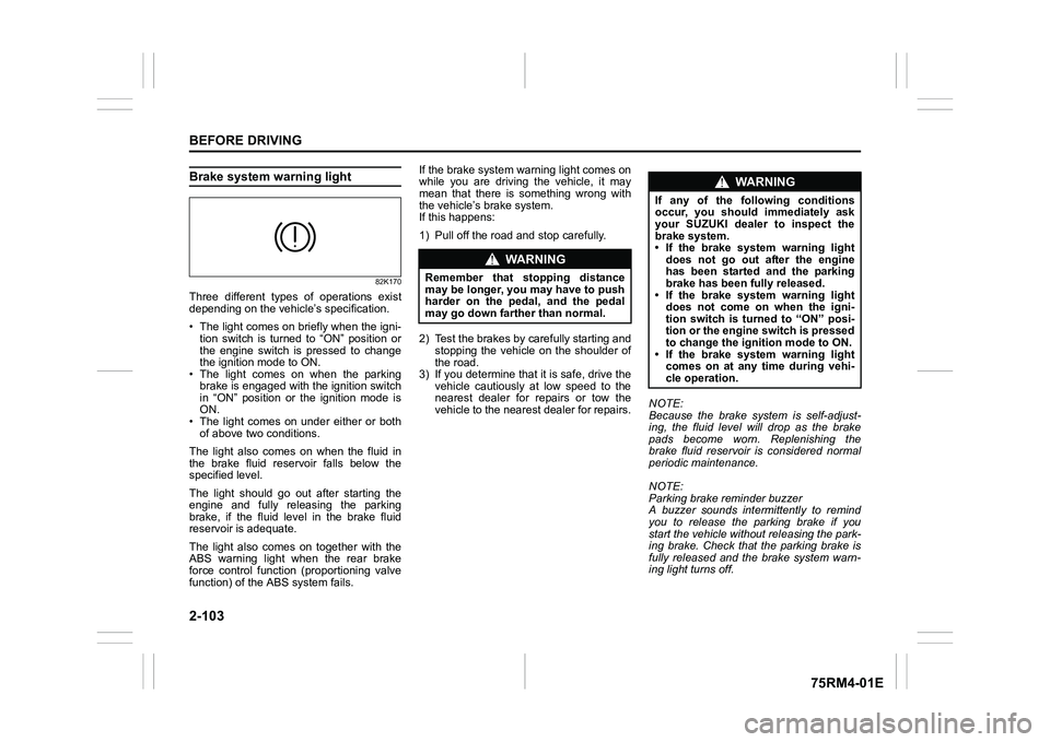
Brake system warning light
82K170
Three different types of operations exist
depending on the vehicle’s specification.
• The light comes on briefly when the igni- tion switch is turned to “ON” position or
the engine switch is pressed to change
the ignition mode to ON.
• The light comes on when the parking
brake is engaged with the ignition switch
in “ON” position or the ignition mode is
ON.
• The light comes on under either or both of above two conditions.
The light also comes on when the fluid in
the brake fluid reservoir falls below the
specified level.
The light should go out after starting the
engine and fully releasing the parking
brake, if the fluid level in the brake fluid
reservoir is adequate.
The light also comes on together with the
ABS warning light when the rear brake
force control function (proportioning valve
function) of the ABS system fails. If the brake system warning light comes on
while you are driving the vehicle, it may
mean that there is something wrong with
the vehicle’s brake system.
If this happens:
1) Pull off the road and stop carefully.
2) Test the brakes by carefully starting and
stopping the vehicle on the shoulder of
the road.
3) If you determine that it is safe, drive the
vehicle cautiously at low speed to the
nearest dealer for repairs or tow the
vehicle to the nearest dealer for repairs. NOTE:
Because the brake system is self-adjust-
ing, the fluid level will drop as the brake
pads become worn. Replenishing the
brake fluid reservoir is considered normal
periodic maintenance.
NOTE:
Parking brake reminder buzzer
A buzzer sounds intermittently to remind
you to release the parking brake if you
start the vehicle without releasing the park-
ing brake. Check that the parking brake is
fully released and the brake system warn-
ing light turns off.
WA R N I N G
Remember that stopping distance
may be longer, you may have to push
harder on the pedal, and the pedal
may go down farther than normal.
WA R N I N G
If any of the following conditions
occur, you should immediately ask
your SUZUKI dealer to inspect the
brake system.
• If the brake system warning light
does not go out after the engine
has been started and the parking
brake has been fully released.
• If the brake system warning light does not come on when the igni-
tion switch is turned to “ON” posi-
tion or the engine switch is pressed
to change the ignition mode to ON.
• If the brake system warning light comes on at any time during vehi-
cle operation.
Page 132 of 505
2-109BEFORE DRIVING
75RM4-01E
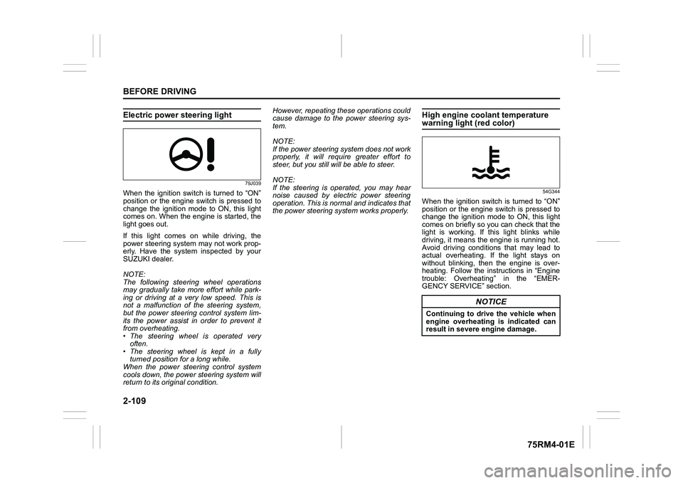
Electric power steering light
79J039
When the ignition switch is turned to “ON”
position or the engine switch is pressed to
change the ignition mode to ON, this light
comes on. When the engine is started, the
light goes out.
If this light comes on while driving, the
power steering system may not work prop-
erly. Have the system inspected by your
SUZUKI dealer.
NOTE:
The following steering wheel operations
may gradually take more effort while park-
ing or driving at a very low speed. This is
not a malfunction of the steering system,
but the power steering control system lim-
its the power assist in order to prevent it
from overheating.
• The steering wheel is operated veryoften.
• The steering wheel is kept in a fully turned position for a long while.
When the power steering control system
cools down, the powe r steering system will
return to its original condition. However, repeating these operations could
cause damage to the power steering sys-
tem.
NOTE:
If the power steering system does not work
properly, it will require greater effort to
steer, but you still will be able to steer.
NOTE:
If the steering is operated, you may hear
noise caused by electric power steering
operation. This is normal and indicates that
the power steering system works properly.
High engine coolant temperature warning light (red color)
54G344
When the ignition switch is turned to “ON”
position or the engine switch is pressed to
change the ignition mode to ON, this light
comes on briefly so you can check that the
light is working. If this light blinks while
driving, it means the engine is running hot.
Avoid driving conditions that may lead to
actual overheating. If the light stays on
without blinking, then the engine is over-
heating. Follow the instructions in “Engine
trouble: Overheating” in the “EMER-
GENCY SERVICE” section.
NOTICE
Continuing to drive the vehicle when
engine overheating is indicated can
result in severe engine damage.
Page 138 of 505
2-115BEFORE DRIVING
75RM4-01E
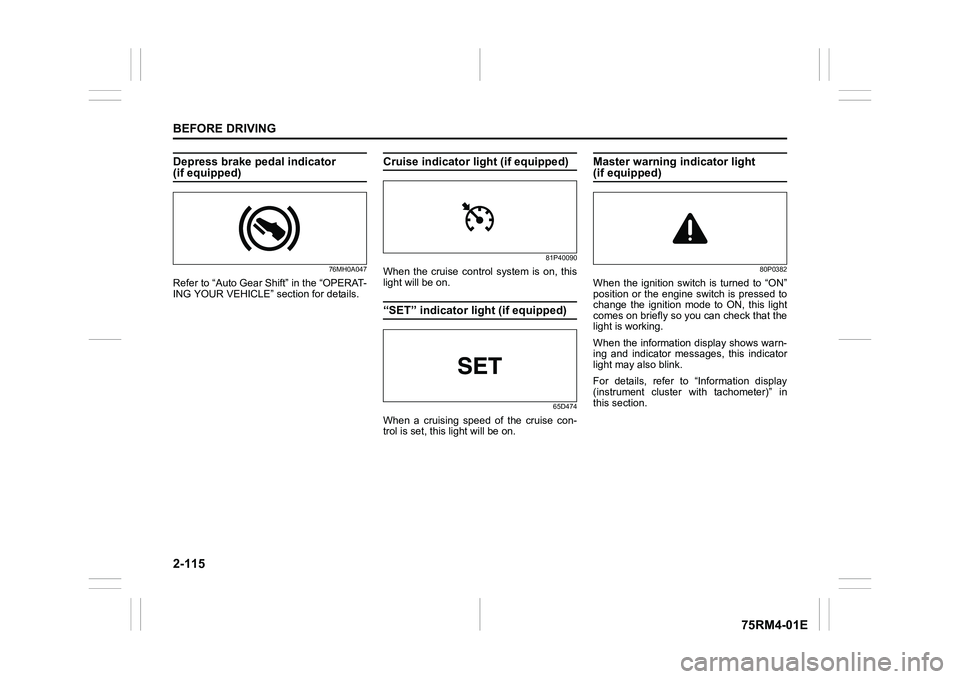
Depress brake pedal indicator (if equipped)
76MH0A047
Refer to “Auto Gear Shift” in the “OPERAT-
ING YOUR VEHICLE” section for details.
Cruise indicator light (if equipped)
81P40090
When the cruise control system is on, this
light will be on.“SET” indicator light (if equipped)
65D474
When a cruising speed of the cruise con-
trol is set, this light will be on.
Master warning indicator light (if equipped)
80P0382
When the ignition switch is turned to “ON”
position or the engine switch is pressed to
change the ignition mode to ON, this light
comes on briefly so you can check that the
light is working.
When the information display shows warn-
ing and indicator messages, this indicator
light may also blink.
For details, refer to “Information display
(instrument cluster with tachometer)” in
this section.
Page 149 of 505
2-126
BEFORE DRIVING
75RM4-01E
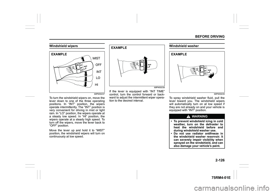
Windshield wipers
68PM00237
To turn the windshield wipers on, move the
lever down to one of the three operating
positions. In “INT” position, the wipers
operate intermittently. The “INT” position is
very convenient for driving in mist or light
rain. In “LO” position, the wipers operate at
a steady low speed. In “HI” position, the
wipers operate at a steady high speed. To
turn off the wipers, move the lever back to
“OFF” position.
Move the lever up and hold it to “MIST”
position, the windshield wipers will turn on
continuously at low speed.
68PM00238
If the lever is equipped with “INT TIME”
control, turn the control forward or back-
ward to adjust the int ermittent wiper opera-
tion to the desired interval.
Windshield washer
68PM00239
To spray windshield washer fluid, pull the
lever toward you. The windshield wipers
will automatically turn on at low speed if
they are not already on and your vehicle is
equipped with “INT” position.
EXAMPLE
EXAMPLE
WA R N I N G
• To prevent windshield icing in cold weather, turn on the defroster to
heat the windshield before and
during windshield washer use.
• Do not use radiator antifreeze in
the windshield washer reservoir. It
can severely impair visibility when
sprayed on the windshield, and can
also damage your vehicle’s paint.EXAMPLE