air SUZUKI JIMNY 2005 3.G Service Workshop Manual
[x] Cancel search | Manufacturer: SUZUKI, Model Year: 2005, Model line: JIMNY, Model: SUZUKI JIMNY 2005 3.GPages: 687, PDF Size: 13.38 MB
Page 278 of 687
Downloaded from www.Manualslib.com manuals search engine BRAKES 5-17
On-Vehicle Service
Air Bleeding of Brake System
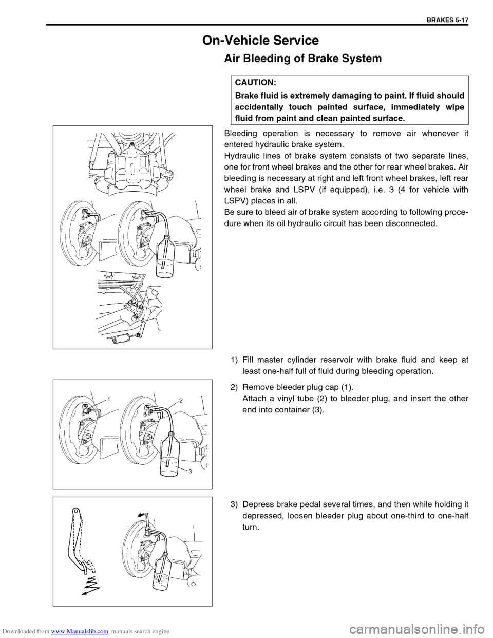
Bleeding operation is necessary to remove air whenever it
entered hydraulic brake system.
Hydraulic lines of brake system consists of two separate lines,
one for front wheel brakes and the other for rear wheel brakes. Air
bleeding is necessary at right and left front wheel brakes, left rear
wheel brake and LSPV (if equipped), i.e. 3 (4 for vehicle with
LSPV) places in all.
Be sure to bleed air of brake system according to following proce-
dure when its oil hydraulic circuit has been disconnected.
1) Fill master cylinder reservoir with brake fluid and keep at
least one-half full of fluid during bleeding operation.
2) Remove bleeder plug cap (1).
Attach a vinyl tube (2) to bleeder plug, and insert the other
end into container (3).
3) Depress brake pedal several times, and then while holding it
depressed, loosen bleeder plug about one-third to one-half
turn. CAUTION:
Brake fluid is extremely damaging to paint. If fluid should
accidentally touch painted surface, immediately wipe
fluid from paint and clean painted surface.
Page 279 of 687
Downloaded from www.Manualslib.com manuals search engine 5-18 BRAKES
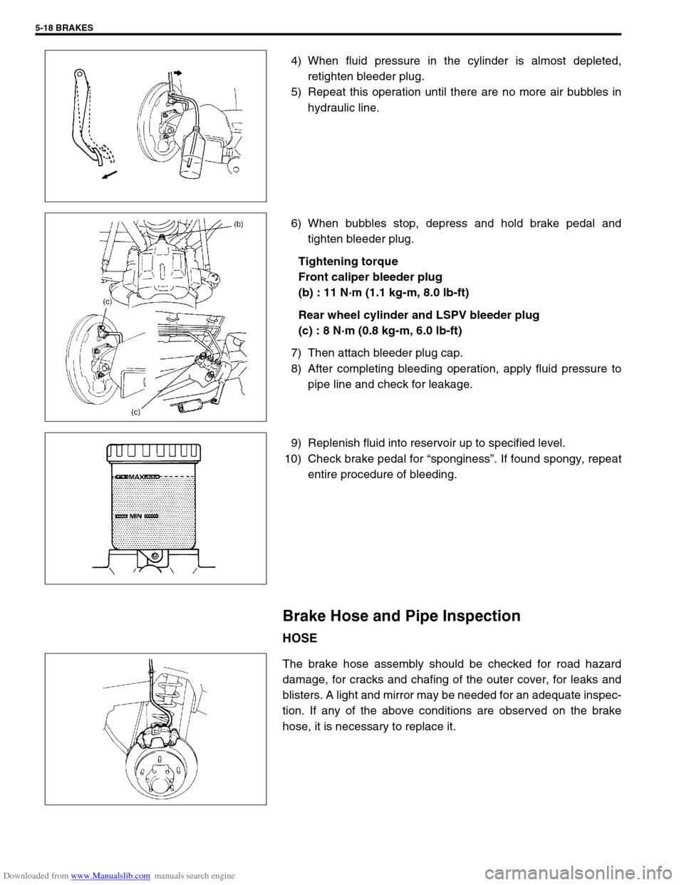
4) When fluid pressure in the cylinder is almost depleted,
retighten bleeder plug.
5) Repeat this operation until there are no more air bubbles in
hydraulic line.
6) When bubbles stop, depress and hold brake pedal and
tighten bleeder plug.
Tightening torque
Front caliper bleeder plug
(b) : 11 N·m (1.1 kg-m, 8.0 lb-ft)
Rear wheel cylinder and LSPV bleeder plug
(c) : 8 N·m (0.8 kg-m, 6.0 lb-ft)
7) Then attach bleeder plug cap.
8) After completing bleeding operation, apply fluid pressure to
pipe line and check for leakage.
9) Replenish fluid into reservoir up to specified level.
10) Check brake pedal for “sponginess”. If found spongy, repeat
entire procedure of bleeding.
Brake Hose and Pipe Inspection
HOSE
The brake hose assembly should be checked for road hazard
damage, for cracks and chafing of the outer cover, for leaks and
blisters. A light and mirror may be needed for an adequate inspec-
tion. If any of the above conditions are observed on the brake
hose, it is necessary to replace it.
Page 283 of 687
Downloaded from www.Manualslib.com manuals search engine 5-22 BRAKES
Caliper assembly
REMOVAL
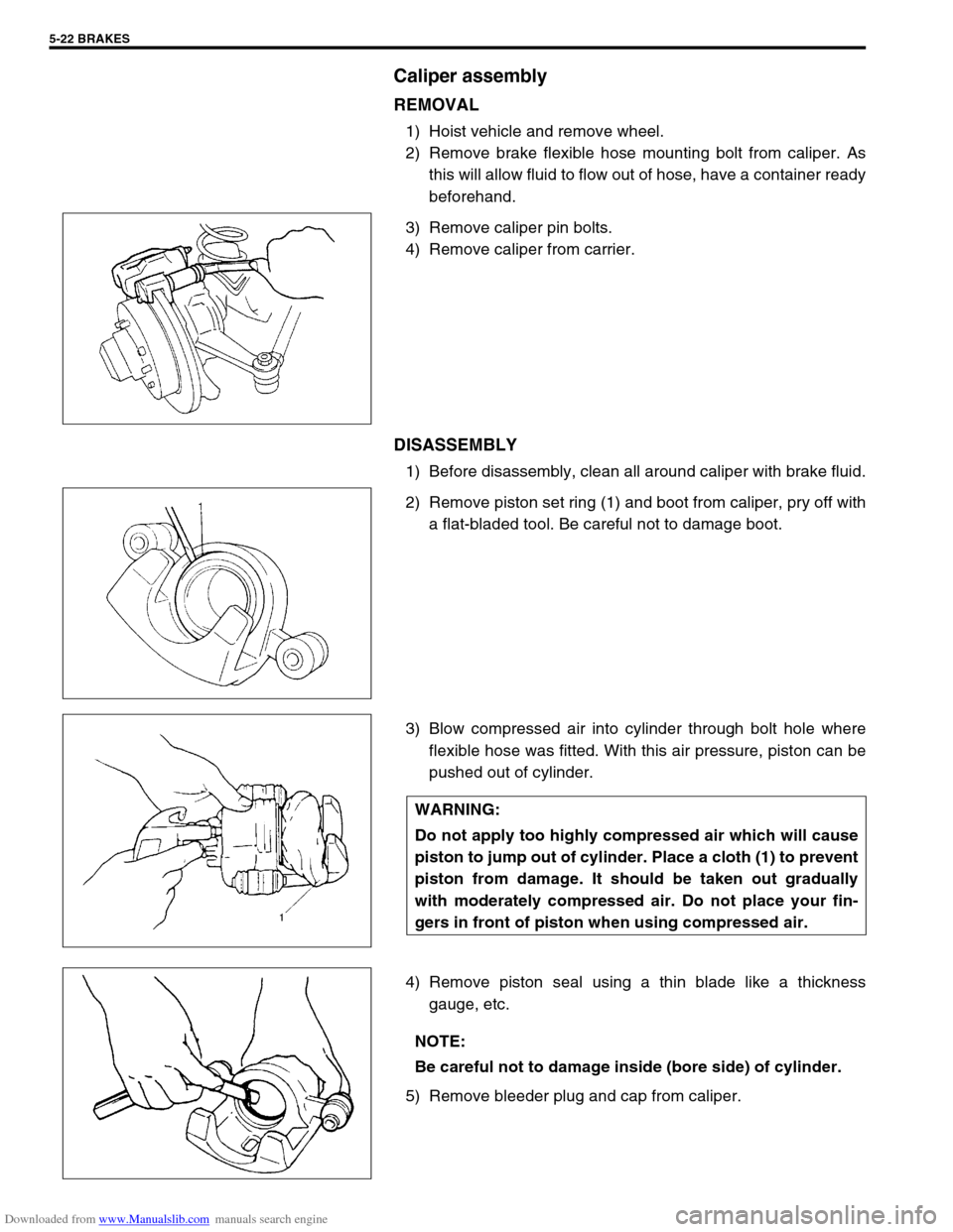
1) Hoist vehicle and remove wheel.
2) Remove brake flexible hose mounting bolt from caliper. As
this will allow fluid to flow out of hose, have a container ready
beforehand.
3) Remove caliper pin bolts.
4) Remove caliper from carrier.
DISASSEMBLY
1) Before disassembly, clean all around caliper with brake fluid.
2) Remove piston set ring (1) and boot from caliper, pry off with
a flat-bladed tool. Be careful not to damage boot.
3) Blow compressed air into cylinder through bolt hole where
flexible hose was fitted. With this air pressure, piston can be
pushed out of cylinder.
4) Remove piston seal using a thin blade like a thickness
gauge, etc.
5) Remove bleeder plug and cap from caliper.
WARNING:
Do not apply too highly compressed air which will cause
piston to jump out of cylinder. Place a cloth (1) to prevent
piston from damage. It should be taken out gradually
with moderately compressed air. Do not place your fin-
gers in front of piston when using compressed air.
NOTE:
Be careful not to damage inside (bore side) of cylinder.
Page 285 of 687
Downloaded from www.Manualslib.com manuals search engine 5-24 BRAKES
ASSEMBLY
1) Check that slide bushes and boots for wear, corrosion, dam-
age, movement or deterioration. If it is found faulty, correct or
replace.
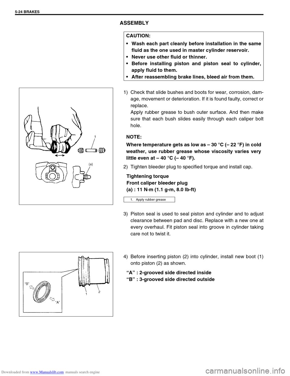
Apply rubber grease to bush outer surface. And then make
sure that each bush slides easily through each caliper bolt
hole.
2) Tighten bleeder plug to specified torque and install cap.
Tightening torque
Front caliper bleeder plug
(a) : 11 N·m (1.1 g-m, 8.0 lb-ft)
3) Piston seal is used to seal piston and cylinder and to adjust
clearance between pad and disc. Replace with a new one at
every overhaul. Fit piston seal into groove in cylinder taking
care not to twist it.
4) Before inserting piston (2) into cylinder, install new boot (1)
onto piston (2) as shown.
“A” : 2-grooved side directed inside
“B” : 3-grooved side directed outside CAUTION:
Wash each part cleanly before installation in the same
fluid as the one used in master cylinder reservoir.
Never use other fluid or thinner.
Before installing piston and piston seal to cylinder,
apply fluid to them.
After reassembling brake lines, bleed air from them.
NOTE:
Where temperature gets as low as – 30 °C (– 22 °F) in cold
weather, use rubber grease whose viscosity varies very
little even at – 40 °C (– 40 °F).
1. Apply rubber grease
Page 299 of 687
Downloaded from www.Manualslib.com manuals search engine 5-38 BRAKES
INSTALLATION
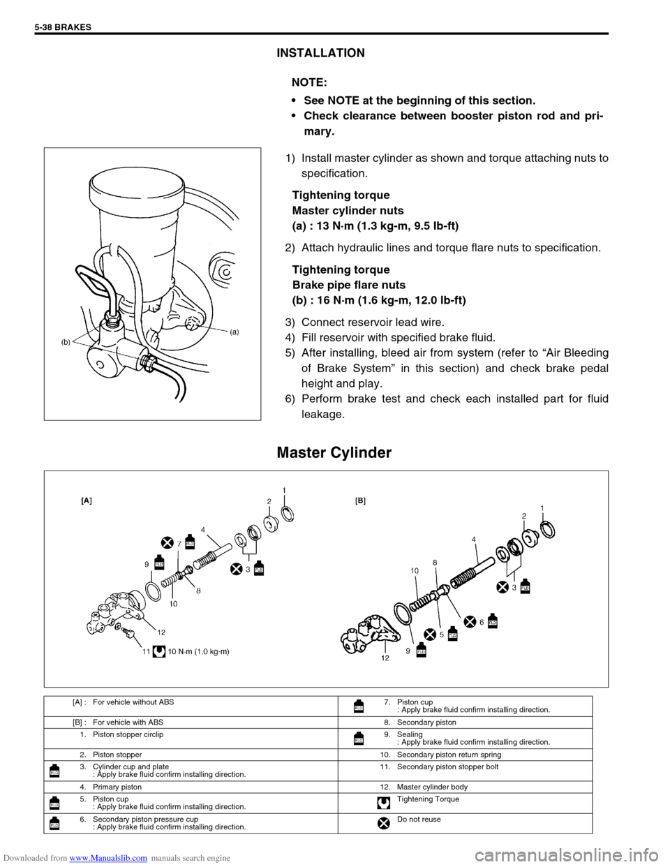
1) Install master cylinder as shown and torque attaching nuts to
specification.
Tightening torque
Master cylinder nuts
(a) : 13 N·m (1.3 kg-m, 9.5 Ib-ft)
2) Attach hydraulic lines and torque flare nuts to specification.
Tightening torque
Brake pipe flare nuts
(b) : 16 N·m (1.6 kg-m, 12.0 lb-ft)
3) Connect reservoir lead wire.
4) Fill reservoir with specified brake fluid.
5) After installing, bleed air from system (refer to “Air Bleeding
of Brake System” in this section) and check brake pedal
height and play.
6) Perform brake test and check each installed part for fluid
leakage.
Master Cylinder
NOTE:
See NOTE at the beginning of this section.
Check clearance between booster piston rod and pri-
mary.
[A] : For vehicle without ABS 7. Piston cup
: Apply brake fluid confirm installing direction.
[B] : For vehicle with ABS 8. Secondary piston
1. Piston stopper circlip 9. Sealing
: Apply brake fluid confirm installing direction.
2. Piston stopper 10. Secondary piston return spring
3. Cylinder cup and plate
: Apply brake fluid confirm installing direction.11. Secondary piston stopper bolt
4. Primary piston 12. Master cylinder body
5. Piston cup
: Apply brake fluid confirm installing direction.Tightening Torque
6. Secondary piston pressure cup
: Apply brake fluid confirm installing direction.Do not reuse
Page 300 of 687
![SUZUKI JIMNY 2005 3.G Service Workshop Manual Downloaded from www.Manualslib.com manuals search engine BRAKES 5-39
DISASSEMBLY
1) Remove circlip (1).
2) Remove primary piston.
3) [For vehicle with ABS]
Pull out primary piston assembly straight so SUZUKI JIMNY 2005 3.G Service Workshop Manual Downloaded from www.Manualslib.com manuals search engine BRAKES 5-39
DISASSEMBLY
1) Remove circlip (1).
2) Remove primary piston.
3) [For vehicle with ABS]
Pull out primary piston assembly straight so](/img/20/7588/w960_7588-299.png)
Downloaded from www.Manualslib.com manuals search engine BRAKES 5-39
DISASSEMBLY
1) Remove circlip (1).
2) Remove primary piston.
3) [For vehicle with ABS]
Pull out primary piston assembly straight so as not to cause
any damage to inside o cylinder wall.
Pull out secondary piston assembly straight so as not to
cause any damage to inside of cylinder wall and by tapping
flange with a piece of wood or something soft.
4) [For vehicle without ABS]
Remove piston stopper bolt (1). Then remove secondary pis-
ton by blowing compressed air (2) into hole from which pis-
ton stopper bolt was removed.
Be cautions during removal as secondary piston jumps out.
INSPECTION
Inspect all disassembled parts for wear or damage, and
replace parts if necessary.
Inspect master cylinder bore for scoring or corrosion. It is
best to replace corroded cylinder.
Corrosion can be identified as pits or excessive roughness.
2. Master cylinder
NOTE:
Wash disassembled parts with brake fluid.
Do not reuse piston cups.
NOTE:
Polishing bore of master cylinder with cast aluminum
body with anything abrasive is prohibited, as damage to
cylinder bore may occur.
[A]: Vehicle equipped with ABS
[B]: Vehicle not equipped with ABS
Page 303 of 687
Downloaded from www.Manualslib.com manuals search engine 5-42 BRAKES
LSPV (Load Sensing Proportioning Valve) Assembly (If Equipped)
REMOVAL
1) Clean around reservoir cap and take out fluid with syringe or
such.
2) Hoist vehicle.
3) Disconnect brake pipes from LSPV.
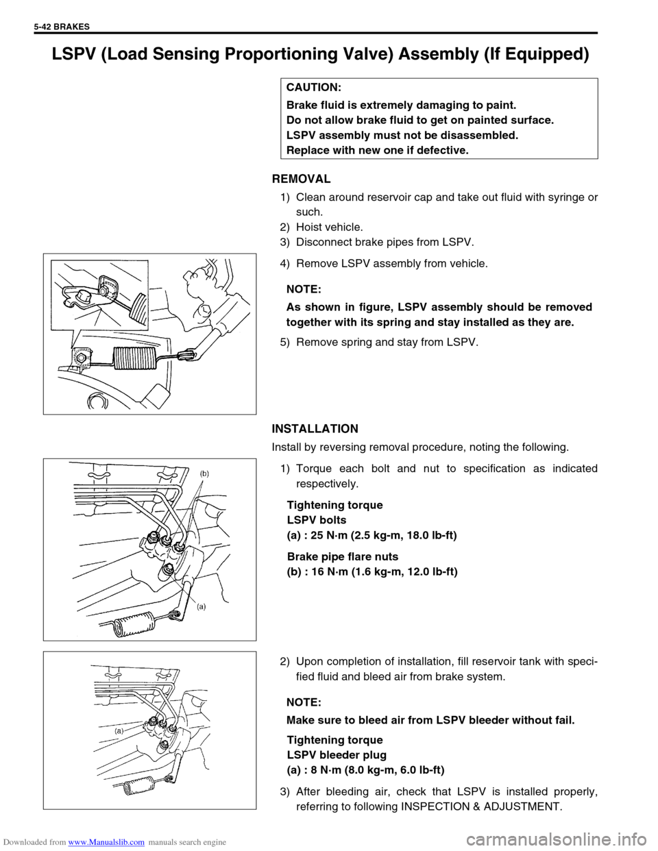
4) Remove LSPV assembly from vehicle.
5) Remove spring and stay from LSPV.
INSTALLATION
Install by reversing removal procedure, noting the following.
1) Torque each bolt and nut to specification as indicated
respectively.
Tightening torque
LSPV bolts
(a) : 25 N·m (2.5 kg-m, 18.0 lb-ft)
Brake pipe flare nuts
(b) : 16 N·m (1.6 kg-m, 12.0 lb-ft)
2) Upon completion of installation, fill reservoir tank with speci-
fied fluid and bleed air from brake system.
Tightening torque
LSPV bleeder plug
(a) : 8 N·m (8.0 kg-m, 6.0 lb-ft)
3) After bleeding air, check that LSPV is installed properly,
referring to following INSPECTION & ADJUSTMENT. CAUTION:
Brake fluid is extremely damaging to paint.
Do not allow brake fluid to get on painted surface.
LSPV assembly must not be disassembled.
Replace with new one if defective.
NOTE:
As shown in figure, LSPV assembly should be removed
together with its spring and stay installed as they are.
NOTE:
Make sure to bleed air from LSPV bleeder without fail.
Page 305 of 687
Downloaded from www.Manualslib.com manuals search engine 5-44 BRAKES
P (Proportioning) Valve
REMOVAL
1) Clean around reservoir cap and take out fluid with syringe or
such.
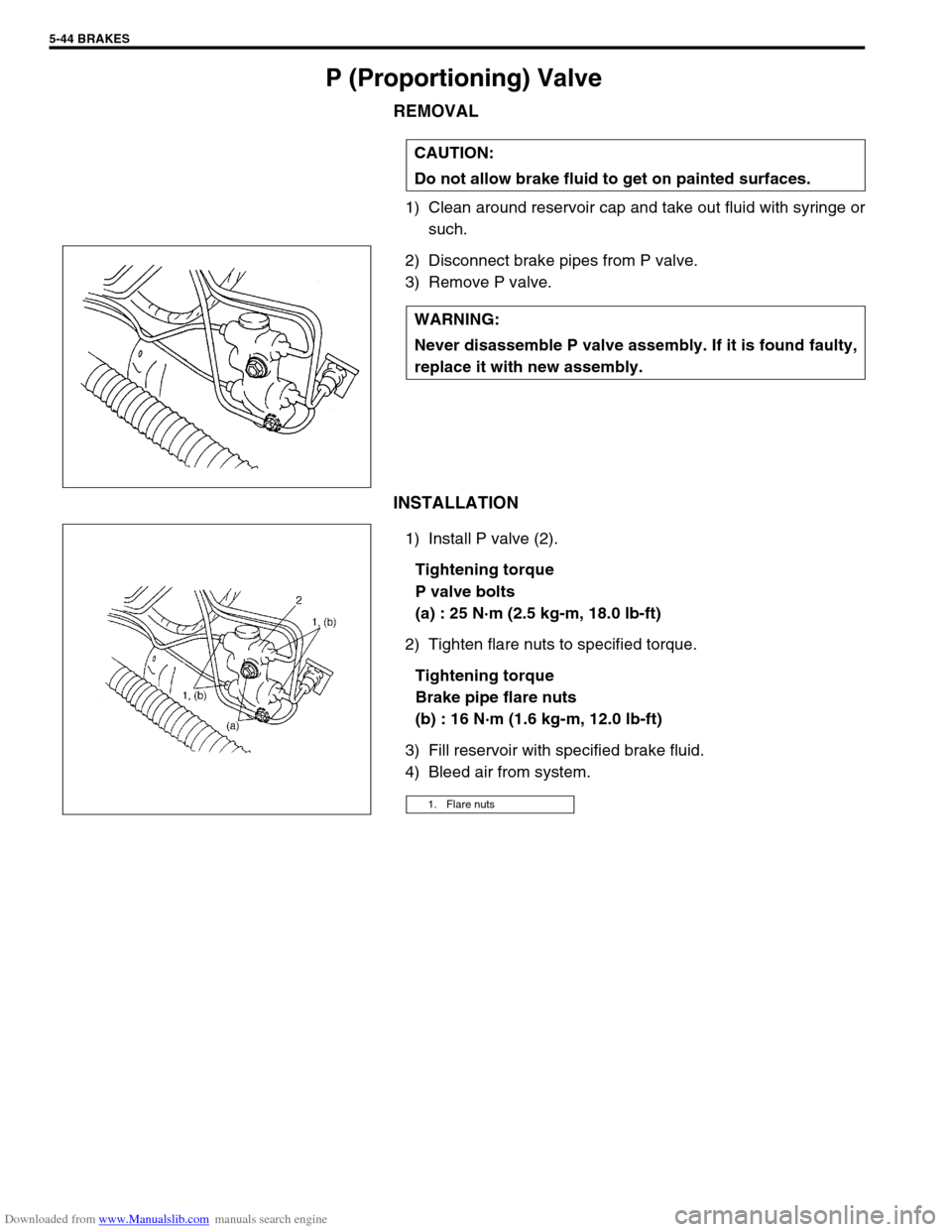
2) Disconnect brake pipes from P valve.
3) Remove P valve.
INSTALLATION
1) Install P valve (2).
Tightening torque
P valve bolts
(a) : 25 N·m (2.5 kg-m, 18.0 lb-ft)
2) Tighten flare nuts to specified torque.
Tightening torque
Brake pipe flare nuts
(b) : 16 N·m (1.6 kg-m, 12.0 lb-ft)
3) Fill reservoir with specified brake fluid.
4) Bleed air from system.CAUTION:
Do not allow brake fluid to get on painted surfaces.
WARNING:
Never disassemble P valve assembly. If it is found faulty,
replace it with new assembly.
1. Flare nuts
Page 318 of 687
Downloaded from www.Manualslib.com manuals search engine ANTILOCK BRAKE SYSTEM (ABS) 5E-1
6F1
6F2
6G
6H
6K
7A
7A1
7B1
7C1
7D
7E
7F
8E
5E
9
10
10A
10B
10
10A
10B
SECTION 5E
ANTILOCK BRAKE SYSTEM (ABS)
CONTENTS
General Description ....................................... 5E-2
System Schematic ....................................... 5E-3
ABS Component Parts Location .................. 5E-4
ABS Control Module ..................................... 5E-5
Self-diagnosis function ............................. 5E-5
Fail-safe function ...................................... 5E-5
Diagnosis ........................................................ 5E-6
Precaution in Diagnosing Troubles .............. 5E-6
ABS Diagnostic Flow Table .......................... 5E-6
“ABS” Warning Lamp Check ........................ 5E-9
Diagnostic Trouble Code (DTC) Check ........ 5E-9
DTC Check (Using SUZUKI Scan Tool) ..... 5E-10
Diagnostic Trouble Code (DTC)
Clearance ................................................... 5E-10
Diagnostic Trouble Code (DTC) Table ....... 5E-11
System Circuit ............................................ 5E-12
Table – A “ABS” Warning Lamp Circuit
Check – Lamp Does Not Come “ON”
at Ignition Switch ON .................................. 5E-14
Table – B “ABS” Warning Lamp Circuit
Check – Lamp Comes “ON” Steady ........... 5E-15
Table – C “ABS” Warning Lamp Circuit
Check – Lamp Flashes Continuously
While Ignition Switch is ON ........................ 5E-16
Table – D Code (DTC) is Not Outputted
Even With Diag. Switch Terminal
Connected to Ground. ................................ 5E-17
DTC C1015 (DTC 15) – G Sensor
Circuit ......................................................... 5E-18
DTC C1016 (DTC 16) – Stop Lamp
Circuit ......................................................... 5E-20
DTC C1021 (DTC 21), DTC C1022
(DTC 22) – Right Front Wheel Speed
Sensor Circuit ............................................. 5E-21
DTC C1025 (DTC 25), DTC C1026
(DTC 26) – Left Front Wheel Speed
Sensor Circuit ............................................. 5E-21DTC C1031 (DTC 31), DTC C1032
(DTC 32) – Right Rear Wheel Speed
Sensor Circuit ............................................ 5E-21
DTC C1035 (DTC 35), DTC C1036
(DTC 36) – Left Rear Wheel Speed
Sensor Circuit ............................................ 5E-21
DTC C1041 (DTC 41), DTC C1042
(DTC 42) – Right Front Solenoid Circuit .... 5E-24
DTC C1045 (DTC 45), DTC C1046
(DTC 46) – Left Front Solenoid Circuit....... 5E-24
DTC C1055 (DTC 55), DTC C1056
(DTC 56) – Rear Solenoid Circuit .............. 5E-24
DTC C1057 (DTC 57) – Power Source
Circuit ......................................................... 5E-25
DTC C1061 (DTC 61) – ABS Pump
Motor Circuit............................................... 5E-26
DTC C1063 (DTC 63) – ABS Fail Safe
Circuit ......................................................... 5E-27
DTC C1071 (DTC 71) – ABS Control
Module ....................................................... 5E-28
On-Vehicle Service ...................................... 5E-29
Precaution .................................................. 5E-29
ABS Hydraulic Unit Operation Check ........ 5E-29
ABS Hydraulic Unit / Control Module
Assembly ................................................... 5E-30
Front Wheel Speed Sensor........................ 5E-32
Front Wheel Sensor Ring........................... 5E-35
Rear Wheel Speed Sensor ........................ 5E-36
Rear Wheel Sensor Ring ........................... 5E-38
G Sensor .................................................... 5E-39
Tightening Torque Specification ................ 5E-40
Special Tool .................................................. 5E-40 NOTE:
All brake fasteners are important attaching parts in that they could affect the performance of vital
parts and systems, and/or could result in major repair expense. They must be replaced with one of
same part number or with an equivalent part if replacement part of lesser quality or substitute design.
Torque values must be used as specified during reassembly to assure proper retention of all parts.
There is to be no welding as it may result in extensive damage and weakening of the metal.
Page 323 of 687

Downloaded from www.Manualslib.com manuals search engine 5E-6 ANTILOCK BRAKE SYSTEM (ABS)
Diagnosis
To ensure that the trouble diagnosis is done accurately and smoothly, observe “Precautions in Diagnosing Trou-
bles” and follow “ABS Diagnostic Flow Table”.
Precaution in Diagnosing Troubles
If the vehicles was operated in any of the following ways, “ABS” warning lamp may light momentarily but this
does not indicate anything abnormal in ABS.
–The vehicle was driven with parking brake pulled.
–The vehicle was driven with brake dragging.
–The vehicle was stuck in mud, sand, etc.
–Wheel spin occurred while driving.
–Wheel(s) was rotated while the vehicle was jacked up.
Be sure to read “Precautions for Electronic Circuit Service” in Section 0A before inspection and observe
what is written there.
Be sure to use the trouble diagnosis procedure as described in the flow table. Failure to follow the flow table
may result in incorrect diagnosis. Some other diag. trouble code may be stored by mistake in the memory of
ABS control module during inspection.
ABS Diagnostic Flow Table
Refer to the following for the details of each step.
Step Action Yes No
1 Perform customer complaint analysis, problem symptom confir-
mation and diagnostic trouble code check record and clear-
ance.
Is there any trouble code?Go to Step 2. Go to Step 5.
2 Perform driving test.
Is trouble symptom identified?Go to Step 3. Go to Step 6.
3 Check diagnostic trouble code.
Is it malfunction code?Go to Step 4. Go to Step 5.
4 Inspect and repair referring to applicable diagnostic trouble
code table in this section. Then perform final confirmation test
after clearing diagnostic trouble code.
Is trouble recur?Go to Step 7. End.
5 Inspect and repair referring to “Diagnosis Table” in Section 5.
Then perform final confirmation test after clearing diagnostic
trouble code.
Is trouble recur?Go to Step 7. End.
6 Check for intermittent problems referring to “Intermittent and
Poor Connection” in Section 0A and related circuit of trouble
code recorded in Step 3. Then perform final confirmation test
after clearing diagnostic trouble code.
Is trouble recur?Go to Step 7. End.
7 Perform diagnostic trouble code check record and clearance.
Is there any trouble code?Go to Step 4. Go to Step 5.