Efi SUZUKI JIMNY 2005 3.G Service User Guide
[x] Cancel search | Manufacturer: SUZUKI, Model Year: 2005, Model line: JIMNY, Model: SUZUKI JIMNY 2005 3.GPages: 687, PDF Size: 13.38 MB
Page 359 of 687

Downloaded from www.Manualslib.com manuals search engine 6-2 ENGINE GENERAL INFORMATION AND DIAGNOSIS
Diagnostic trouble code (DTC) table ......... 6-16
Fail-safe table............................................ 6-19
Visual inspection ....................................... 6-20
Engine basic inspection ............................ 6-21
Engine diagnosis table .............................. 6-23
Scan Tool Data ............................................. 6-28
Scan tool data definitions .......................... 6-30
Inspection of ECM and Its Circuits ................ 6-33
Component Location ..................................... 6-42
Table A-1 Malfunction Indicator Lamp Circuit
Check - Lamp Does Not Come “ON” at Ignition
Switch ON (But Engine at Stop).................... 6-43
Table A-2 Malfunction Indicator Lamp Circuit
Check - Lamp Remains “ON” after Engine
Starts............................................................. 6-44
Table A-3 Malfunction Indicator Lamp Circuit
Check - Mil Flashes at Ignition Switch ON .... 6-45
Table A-4 Malfunction Indicator Lamp Circuit
Check - MIL Does Not Flash, Just Remains
ON or Just Remains OFF Even with Grounding
Diagnosis Switch Terminal............................ 6-45
Table A-5 ECM Power and Ground Circuit
Check - MIL Doesn’t Light at Ignition Switch
ON and Engine Doesn’t Start Though It Is
Cranked Up ................................................... 6-46
DTC P0105 (DTC No.11) Manifold Absolute
Pressure (MAP) Circuit Malfunction .............. 6-48
DTC P0110 (DTC No.18) Intake Air Temp.
(IAT) Circuit Malfunction ............................... 6-51
DTC P0115 (DTC No.19) Engine Coolant
Temperature (ECT) Circuit Malfunction ........ 6-53
DTC P0120 (DTC No.13) Throttle Position
Circuit Malfunction ........................................ 6-55
DTC P0121 Throttle Position Circuit Range /
Performance Problem ................................... 6-57
DTC P0130 (DTC No.14) Heated Oxygen
Sensor (HO2S) Circuit Malfunction
(Sensor-1) ..................................................... 6-59
DTC P0133 Heated Oxygen Sensor (HO2S)
Circuit Slow Response (Sensor-1) ................ 6-61
DTC P0135 (DTC No.14) Heated Oxygen
Sensor (HO2S) Heater Circuit Malfunction
(Sensor-1) ..................................................... 6-62
DTC P0136 Heated Oxygen Sensor (HO2S)
Circuit Malfunction (Sensor-2) ...................... 6-64
DTC P0141 Heated Oxygen Sensor (HO2S)
Heater Circuit Malfunction (Sensor-2)........... 6-66
DTC P0171 Fuel System Too Lean .............. 6-68
DTC P0172 Fuel System Too Rich ............... 6-68
DTC P0300 Random Misfire Detected
(Misfire Detected at 2 or More Cylinders) ..... 6-72DTC P0301 Cylinder 1 Misfire Detected ........ 6-72
DTC P0302 Cylinder 2 Misfire Detected ........ 6-72
DTC P0303 Cylinder 3 Misfire Detected ........ 6-72
DTC P0304 Cylinder 4 Misfire Detected ........ 6-72
DTC P0325 (DTC No.17) Knock Sensor Circuit
Malfunction .................................................... 6-77
DTC P0335 (DTC No.23) Crankshaft Position
(CKP) Sensor Circuit Malfunction .................. 6-79
DTC P0340 (DTC No.15) Camshaft Position
(CMP) Sensor Circuit Malfunction ................. 6-82
DTC P0400 Exhaust Gas Recirculation Flow
Malfunction .................................................... 6-85
DTC P0420 Catalyst System Efficiency below
Threshold ....................................................... 6-88
DTC P0443 Purge Control Valve Circuit
Malfunction .................................................... 6-91
DTC P0481 A/C Condenser Fan Control
Circuit Malfunction ......................................... 6-92
DTC P0500 (DTC No.16) Vehicle Speed
Sensor (VSS) Malfunction ............................. 6-94
DTC P0505 Idle Control System
Malfunction .................................................... 6-96
DTC P0601 Internal Control Module Memory
Check Sum Error (DTC No.71) ...................... 6-98
DTC P1450 Barometric Pressure Sensor
Low / High Input ............................................. 6-99
DTC P1451 Barometric Pressure Sensor
Performance Problem .................................... 6-99
DTC P1500 Engine Starter Signal Circuit
Malfunction .................................................. 6-101
DTC P1510 ECM Back-up Power Supply
Malfunction .................................................. 6-103
DTC P1570 (DTC No.21) ABS Signal Circuit
Malfunction .................................................. 6-104
DTC P1600 Serial Communication Problem
Between ECM and TCM .............................. 6-105
DTC P1717 A/T Drive Range (Park / Neutral
Position) Signal Circuit Malfunction ............. 6-107
Table B-1 Fuel Injector Circuit Check ..........6-109
Table B-2 Fuel Pump and Its Circuit
Check........................................................... 6-110
Table B-3 Fuel Pressure Check................... 6-112
Table B-4 Idle Air Control System Check ....6-114
Table B-5 A/C Signal Circuits Check
(Vehicle with A/C) ........................................ 6-117
Table B-6 Electric Load Signal Circuit
Check........................................................... 6-119
TAble B-7 A/C Condenser Fan Control
System Check.............................................. 6-121
Special Tool ................................................... 6-123
Page 387 of 687

Downloaded from www.Manualslib.com manuals search engine 6-30 ENGINE GENERAL INFORMATION AND DIAGNOSIS
Scan tool data definitions
FUEL SYSTEM (FUEL SYSTEM STATUS)
Air / fuel ratio feedback loop status displayed as either open or closed loop. Open indicates that ECM ignores
feedback from the exhaust oxygen sensor.
Closed indicates final injection duration is corrected for oxygen sensor feedback.
CALC LOAD (CALCULATED LOAD VALUE, %)
Engine load displayed as a percentage of maximum possible load. Value is calculated mathematically using the
formula : actual (current) intake air volume ÷ maximum possible intake air volume x 100%.
COOLANT TEMP. (ENGINE COOLANT TEMPERATURE, °C, °F)
It is detected by engine coolant temp. sensor
SHORT FT B1 (SHORT TERM FUEL TRIM, %)
Short term fuel trim value represents short term corrections to the air / fuel mixture computation. A value of 0
indicates no correction, a value greater than 0 means an enrichment correction, and a value less than 0 implies
an enleanment correction.
LONG FT B1 (LONG TERM FUEL TRIM, %)
Long term fuel trim Value represents long term corrections to the air / fuel mixture computation. A value of 0 indi-
cates no correction, a value greater than 0 means an enrichment correction, and a value less than 0 implies an
enleanment correction.
MAP (INTAKE MANIFOLD ABSOLUTE PRESSURE, kPa, inHg)
It is detected by manifold absolute pressure sensor and used (among other things) to compute engine load.
ENGINE SPEED (rpm)
It is computed by reference pulses from crankshaft position sensor.
VEHICLE SPEED (km/h, MPH)
It is computed based on pulse signals from vehicle speed sensor.
IGNITION ADVANCE (IGNITION TIMING ADVANCE FOR NO.1 CYLINDER, °)
Ignition timing of NO.1 cylinder is commanded by ECM. The actual ignition timing should be checked by using
the timing light.
INTAKE AIR TEMP. (°C, °F)
It is detected by intake air temp. sensor and used to determine the amount of air passing into the intake manifold
as air density varies with temperature.
MAF (MASS AIR FLOW RATE, gm/s, lb/min)
It represents total mass of air entering intake manifold which is computed based on signals from MAP sensor,
IAT sensor, TP sensor, etc.BRAKE SWIgnition switch
ONBrake pedal is depressing ON
Brake pedal is releasing OFF
BLOWER FANIgnition switch
ONBlower fan switch ON ON
Blower fan switch OFF OFF
A/C MAG CLUTCHIgnition switch
ONA/C operating ON
A/C not operating OFF SCAN TOOL DATA CONDITION REFERENCE VALUES
Page 501 of 687
Downloaded from www.Manualslib.com manuals search engine 6A1-20 ENGINE MECHANICAL (M13 ENGINE)
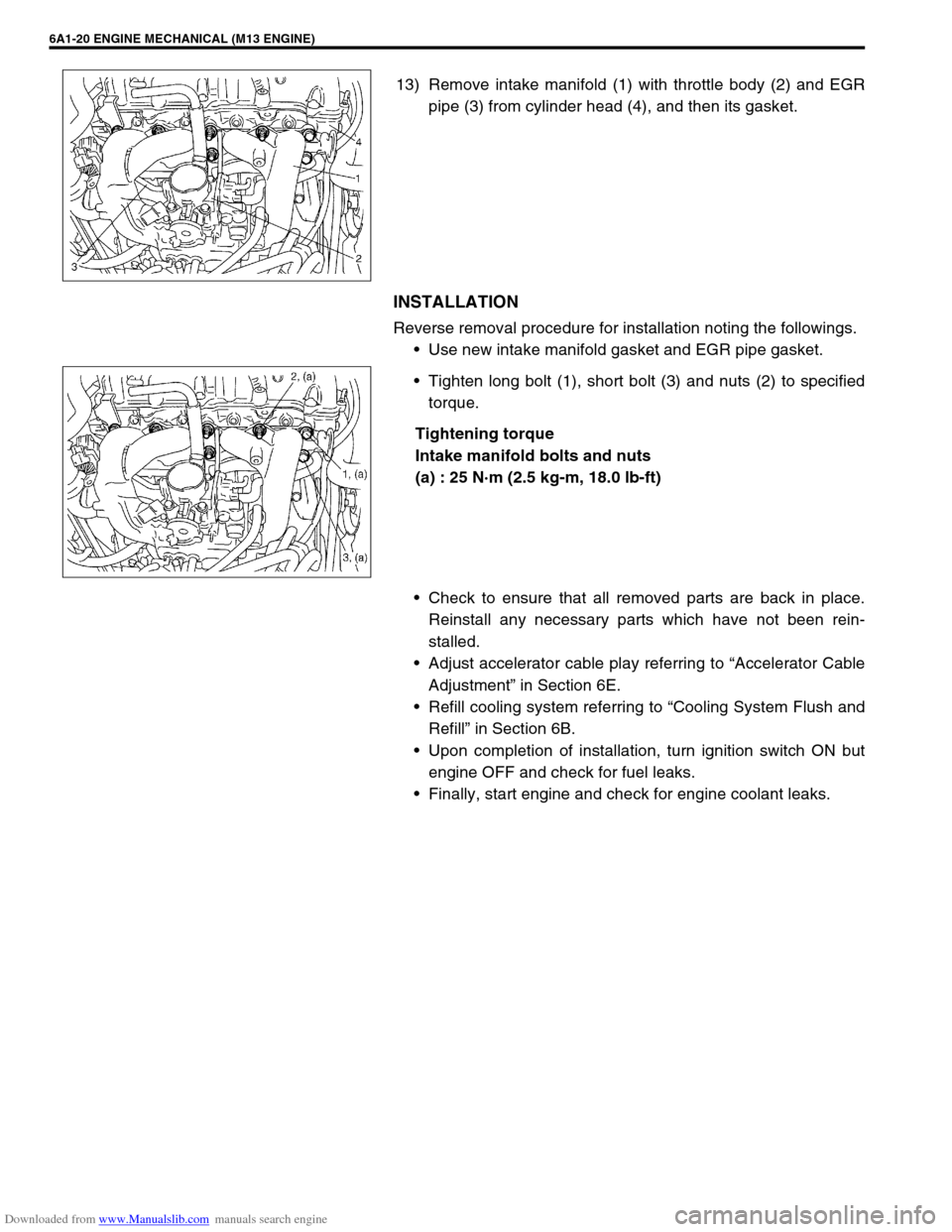
13) Remove intake manifold (1) with throttle body (2) and EGR
pipe (3) from cylinder head (4), and then its gasket.
INSTALLATION
Reverse removal procedure for installation noting the followings.
Use new intake manifold gasket and EGR pipe gasket.
Tighten long bolt (1), short bolt (3) and nuts (2) to specified
torque.
Tightening torque
Intake manifold bolts and nuts
(a) : 25 N·m (2.5 kg-m, 18.0 lb-ft)
Check to ensure that all removed parts are back in place.
Reinstall any necessary parts which have not been rein-
stalled.
Adjust accelerator cable play referring to “Accelerator Cable
Adjustment” in Section 6E.
Refill cooling system referring to “Cooling System Flush and
Refill” in Section 6B.
Upon completion of installation, turn ignition switch ON but
engine OFF and check for fuel leaks.
Finally, start engine and check for engine coolant leaks.
Page 508 of 687
Downloaded from www.Manualslib.com manuals search engine ENGINE MECHANICAL (M13 ENGINE) 6A1-27
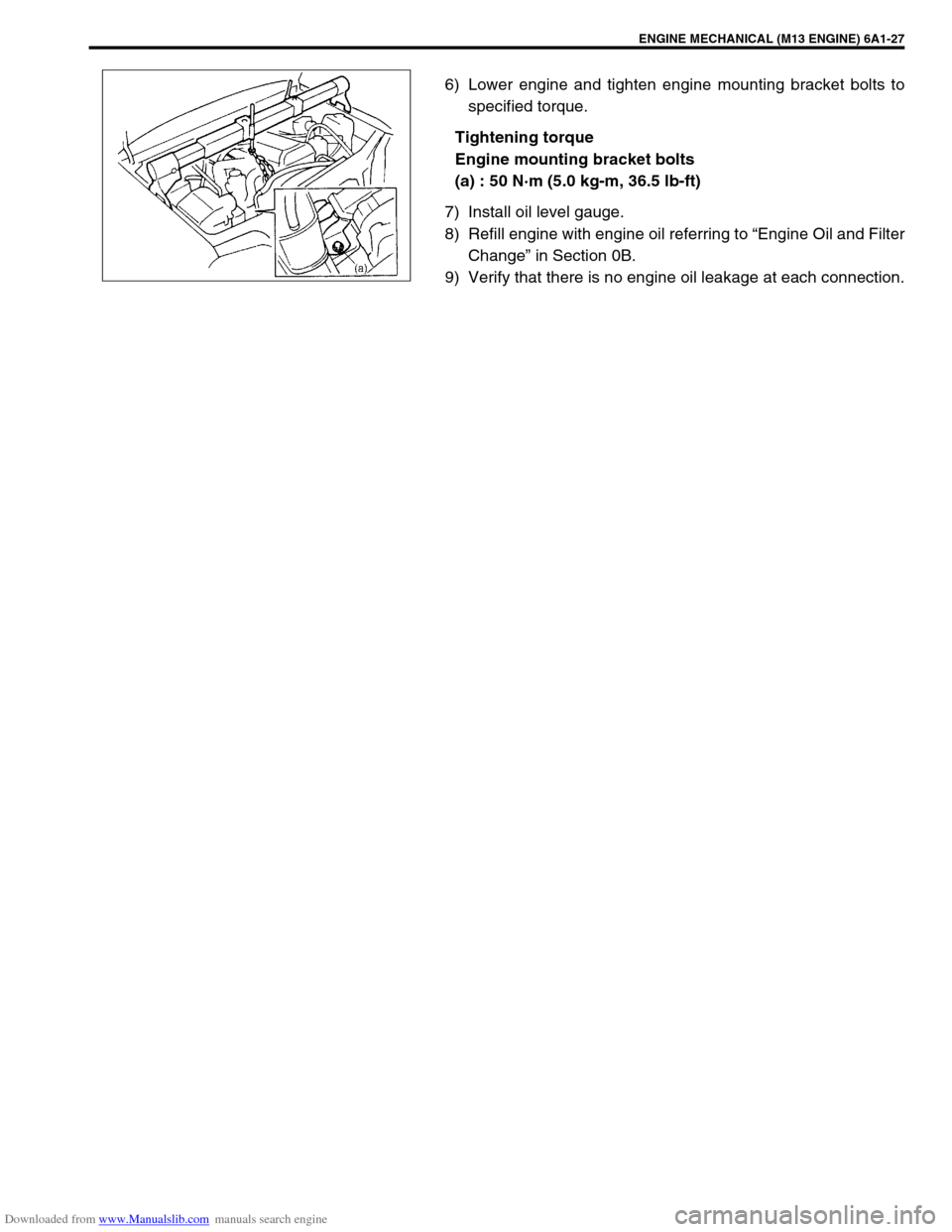
6) Lower engine and tighten engine mounting bracket bolts to
specified torque.
Tightening torque
Engine mounting bracket bolts
(a) : 50 N·m (5.0 kg-m, 36.5 lb-ft)
7) Install oil level gauge.
8) Refill engine with engine oil referring to “Engine Oil and Filter
Change” in Section 0B.
9) Verify that there is no engine oil leakage at each connection.
Page 513 of 687
Downloaded from www.Manualslib.com manuals search engine 6A1-32 ENGINE MECHANICAL (M13 ENGINE)
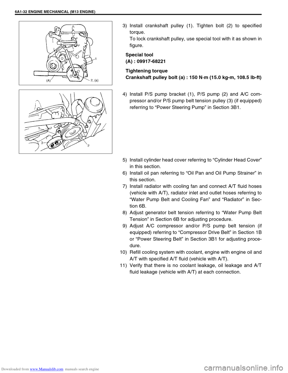
3) Install crankshaft pulley (1). Tighten bolt (2) to specified
torque.
To lock crankshaft pulley, use special tool with it as shown in
figure.
Special tool
(A) : 09917-68221
Tightening torque
Crankshaft pulley bolt (a) : 150 N·m (15.0 kg-m, 108.5 lb-ft)
4) Install P/S pump bracket (1), P/S pump (2) and A/C com-
pressor and/or P/S pump belt tension pulley (3) (if equipped)
referring to “Power Steering Pump” in Section 3B1.
5) Install cylinder head cover referring to “Cylinder Head Cover”
in this section.
6) Install oil pan referring to “Oil Pan and Oil Pump Strainer” in
this section.
7) Install radiator with cooling fan and connect A/T fluid hoses
(vehicle with A/T), radiator inlet and outlet hoses referring to
“Water Pump Belt and Cooling Fan” and “Radiator” in Sec-
tion 6B.
8) Adjust generator belt tension referring to “Water Pump Belt
Tension” in Section 6B for adjusting procedure.
9) Adjust A/C compressor and/or P/S pump belt tension (if
equipped) referring to “Compressor Drive Belt” in Section 1B
or “Power Steering Belt” in Section 3B1 for adjusting proce-
dure.
10) Refill cooling system with coolant, engine with engine oil and
A/T with specified A/T fluid (vehicle with A/T).
11) Verify that there is no coolant leakage, oil leakage and A/T
fluid leakage (vehicle with A/T) at each connection.
Page 528 of 687
Downloaded from www.Manualslib.com manuals search engine ENGINE MECHANICAL (M13 ENGINE) 6A1-47
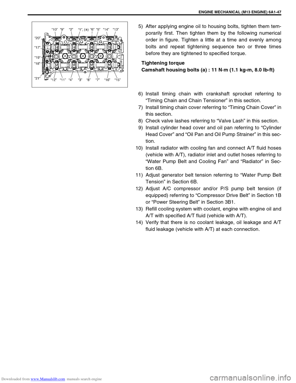
5) After applying engine oil to housing bolts, tighten them tem-
porarily first. Then tighten them by the following numerical
order in figure. Tighten a little at a time and evenly among
bolts and repeat tightening sequence two or three times
before they are tightened to specified torque.
Tightening torque
Camshaft housing bolts (a) : 11 N·m (1.1 kg-m, 8.0 lb-ft)
6) Install timing chain with crankshaft sprocket referring to
“Timing Chain and Chain Tensioner” in this section.
7) Install timing chain cover referring to “Timing Chain Cover” in
this section.
8) Check valve lashes referring to “Valve Lash” in this section.
9) Install cylinder head cover and oil pan referring to “Cylinder
Head Cover” and “Oil Pan and Oil Pump Strainer” in this sec-
tion.
10) Install radiator with cooling fan and connect A/T fluid hoses
(vehicle with A/T), radiator inlet and outlet hoses referring to
“Water Pump Belt and Cooling Fan” and “Radiator” in Sec-
tion 6B.
11) Adjust generator belt tension referring to “Water Pump Belt
Tension” in Section 6B.
12) Adjust A/C compressor and/or P/S pump belt tension (if
equipped) referring to “Compressor Drive Belt” in Section 1B
or “Power Steering Belt” in Section 3B1.
13) Refill cooling system with coolant, engine with engine oil and
A/T with specified A/T fluid (vehicle with A/T).
14) Verify that there is no coolant leakage, oil leakage and A/T
fluid leakage (vehicle with A/T) at each connection.
Page 542 of 687

Downloaded from www.Manualslib.com manuals search engine ENGINE MECHANICAL (M13 ENGINE) 6A1-61
6) Install exhaust manifold stiffener and exhaust pipe referring
to “Exhaust Manifold” in this section.
7) Install camshafts, timing chain and chain cover referring to
“Camshaft, Tappet and Shim”, “Timing Chain and Chain
Tensioner” and “Timing Chain Cover” in this section.
8) Install cylinder head cover and oil pan referring to “Cylinder
Head Cover” and “Oil Pan and Oil Pump Strainer” in this sec-
tion.
9) Install intake manifold stiffener and connect each hoses and
electric lead wires securely.
10) Install air cleaner outlet hoses.
11) Install radiator with cooling fan and connect A/T fluid hoses
(vehicle with A/T), radiator inlet and outlet hoses referring to
“Water Pump Belt and Cooling Fan” and “Radiator” in Sec-
tion 6B.
12) Adjust generator belt tension referring to “Water Pump Belt
Tension” in Section 6B.
13) Adjust A/C compressor and/or P/S pump belt tension (if
equipped) referring to “Compressor Drive Belt” in Section 1B
or “Power Steering Belt” in Section 3B1.
14) Adjust accelerator cable play referring to “Accelerator Cable
Adjustment” in Section 6E.
15) Check to ensure that all removed parts are back in place.
Reinstall any necessary parts which have not been rein-
stalled.
16) Refill cooling system with coolant, engine with engine oil and
A/T with specified A/T fluid (vehicle with A/T).
17) Connect negative cable at battery.
18) Verify that there is no fuel leakage, coolant leakage, oil leak-
age, A/T fluid leakage (vehicle with A/T) and exhaust gas
leakage at each connection.
Page 552 of 687
Downloaded from www.Manualslib.com manuals search engine ENGINE MECHANICAL (M13 ENGINE) 6A1-71
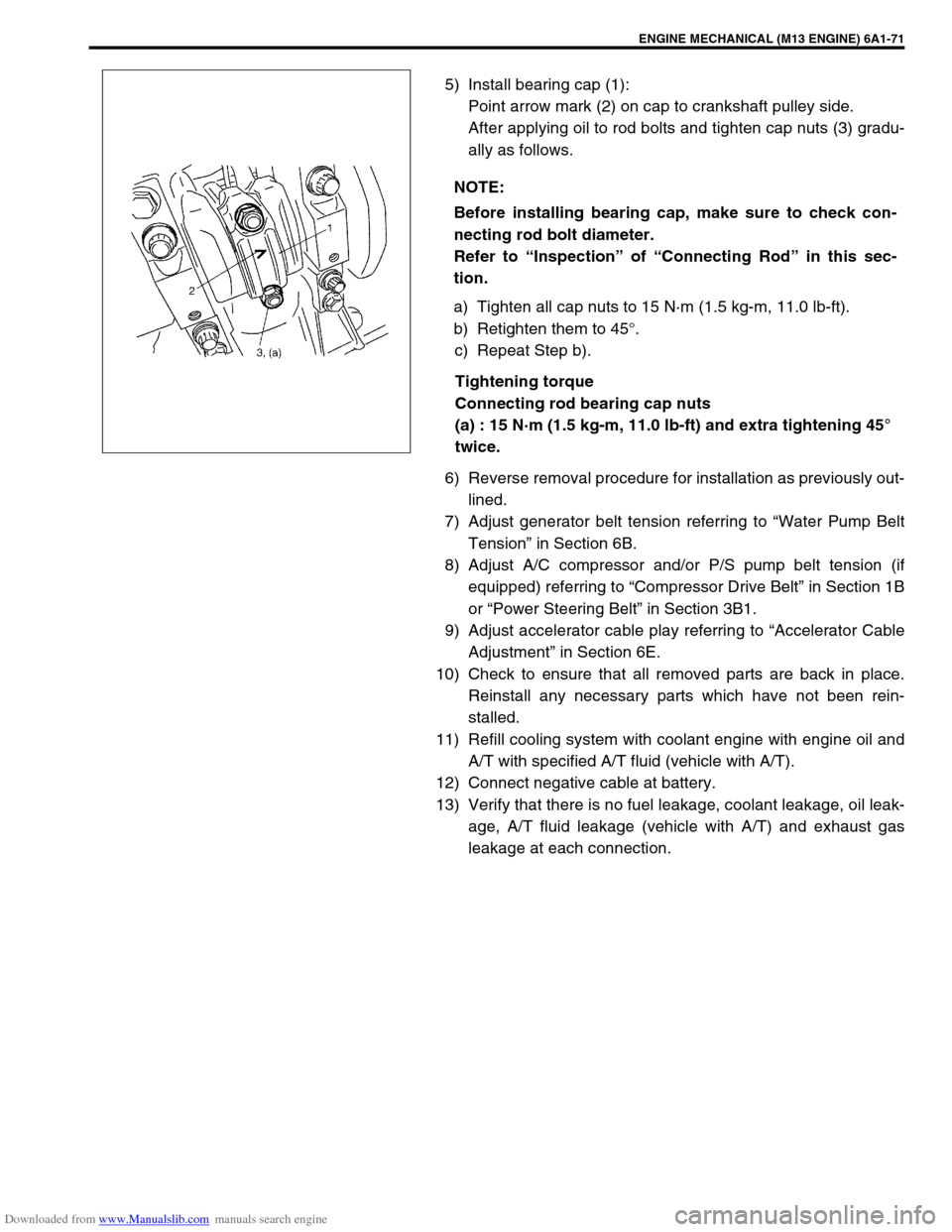
5) Install bearing cap (1):
Point arrow mark (2) on cap to crankshaft pulley side.
After applying oil to rod bolts and tighten cap nuts (3) gradu-
ally as follows.
a) Tighten all cap nuts to 15 N·m (1.5 kg-m, 11.0 lb-ft).
b) Retighten them to 45°.
c) Repeat Step b).
Tightening torque
Connecting rod bearing cap nuts
(a) : 15 N·m (1.5 kg-m, 11.0 lb-ft) and extra tightening 45°
twice.
6) Reverse removal procedure for installation as previously out-
lined.
7) Adjust generator belt tension referring to “Water Pump Belt
Tension” in Section 6B.
8) Adjust A/C compressor and/or P/S pump belt tension (if
equipped) referring to “Compressor Drive Belt” in Section 1B
or “Power Steering Belt” in Section 3B1.
9) Adjust accelerator cable play referring to “Accelerator Cable
Adjustment” in Section 6E.
10) Check to ensure that all removed parts are back in place.
Reinstall any necessary parts which have not been rein-
stalled.
11) Refill cooling system with coolant engine with engine oil and
A/T with specified A/T fluid (vehicle with A/T).
12) Connect negative cable at battery.
13) Verify that there is no fuel leakage, coolant leakage, oil leak-
age, A/T fluid leakage (vehicle with A/T) and exhaust gas
leakage at each connection. NOTE:
Before installing bearing cap, make sure to check con-
necting rod bolt diameter.
Refer to “Inspection” of “Connecting Rod” in this sec-
tion.
Page 559 of 687
Downloaded from www.Manualslib.com manuals search engine 6A1-78 ENGINE MECHANICAL (M13 ENGINE)
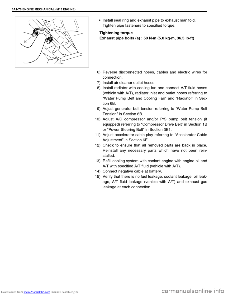
Install seal ring and exhaust pipe to exhaust manifold.
Tighten pipe fasteners to specified torque.
Tightening torque
Exhaust pipe bolts (a) : 50 N·m (5.0 kg-m, 36.5 lb-ft)
6) Reverse disconnected hoses, cables and electric wires for
connection.
7) Install air cleaner outlet hoses.
8) Install radiator with cooling fan and connect A/T fluid hoses
(vehicle with A/T), radiator inlet and outlet hoses referring to
“Water Pump Belt and Cooling Fan” and “Radiator” in Sec-
tion 6B.
9) Adjust generator belt tension referring to “Water Pump Belt
Tension” in Section 6B.
10) Adjust A/C compressor and/or P/S pump belt tension (if
equipped) referring to “Compressor Drive Belt” in Section 1B
or “Power Steering Belt” in Section 3B1.
11) Adjust accelerator cable play referring to “Accelerator Cable
Adjustment” in Section 6E.
12) Check to ensure that all removed parts are back in place.
Reinstall any necessary parts which have not been rein-
stalled.
13) Refill cooling system with coolant engine with engine oil and
A/T with specified A/T fluid (vehicle with A/T).
14) Connect negative cable at battery.
15) Verify that there is no fuel leakage, coolant leakage, oil leak-
age, A/T fluid leakage (vehicle with A/T) and exhaust gas
leakage at each connection.
Page 578 of 687

Downloaded from www.Manualslib.com manuals search engine ENGINE COOLING 6B-1
6B
SECTION 6B
ENGINE COOLING
CONTENTS
General Description ........................................6B-2
Cooling System Circulation ........................... 6B-2
Radiator Cap ................................................. 6B-3
Coolant Reservoir ......................................... 6B-3
Water Pump .................................................. 6B-4
Thermostat .................................................... 6B-4
Cooling Fan Clutch ........................................ 6B-4
Coolant (Water) Temperature Gauge............ 6B-4
Diagnosis .........................................................6B-5
Maintenance ....................................................6B-6
Coolant .......................................................... 6B-6
Coolant Level ................................................ 6B-7
Cooling System Service ................................ 6B-7Cooling System Flush and Refill ................... 6B-8
Water Pump Belt Tension ............................. 6B-9
On-Vehicle Service ....................................... 6B-10
Cooling System Component ....................... 6B-10
Coolant Draining ......................................... 6B-11
Cooling Water Pipes or Hoses .................... 6B-11
Thermostat .................................................. 6B-11
Water Pump Belt and Cooling Fan ............. 6B-13
Radiator ...................................................... 6B-14
Water Pump ................................................ 6B-15
Required Service Material ............................ 6B-17
Tightening Torque Specification ................. 6B-17