Efi SUZUKI JIMNY 2005 3.G Service Workshop Manual
[x] Cancel search | Manufacturer: SUZUKI, Model Year: 2005, Model line: JIMNY, Model: SUZUKI JIMNY 2005 3.GPages: 687, PDF Size: 13.38 MB
Page 28 of 687
Downloaded from www.Manualslib.com manuals search engine GENERAL INFORMATION 0A-23
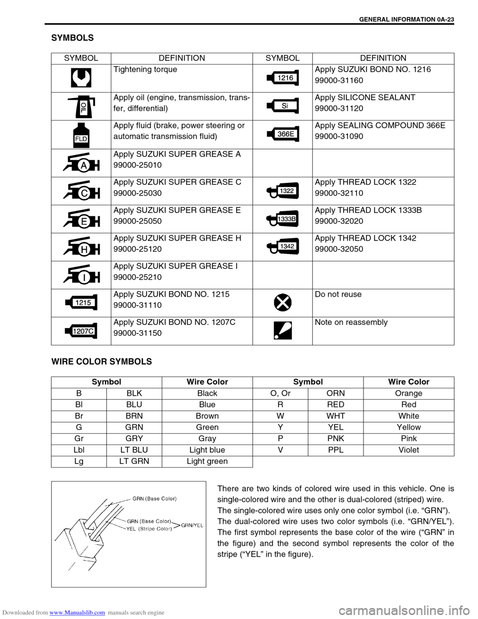
SYMBOLS
WIRE COLOR SYMBOLS
There are two kinds of colored wire used in this vehicle. One is
single-colored wire and the other is dual-colored (striped) wire.
The single-colored wire uses only one color symbol (i.e. “GRN”).
The dual-colored wire uses two color symbols (i.e. “GRN/YEL”).
The first symbol represents the base color of the wire (“GRN” in
the figure) and the second symbol represents the color of the
stripe (“YEL” in the figure). SYMBOL DEFINITION SYMBOL DEFINITION
Tightening torque Apply SUZUKI BOND NO. 1216
99000-31160
Apply oil (engine, transmission, trans-
fer, differential)Apply SILICONE SEALANT
99000-31120
Apply fluid (brake, power steering or
automatic transmission fluid)Apply SEALING COMPOUND 366E
99000-31090
Apply SUZUKI SUPER GREASE A
99000-25010
Apply SUZUKI SUPER GREASE C
99000-25030Apply THREAD LOCK 1322
99000-32110
Apply SUZUKI SUPER GREASE E
99000-25050Apply THREAD LOCK 1333B
99000-32020
Apply SUZUKI SUPER GREASE H
99000-25120Apply THREAD LOCK 1342
99000-32050
Apply SUZUKI SUPER GREASE I
99000-25210
Apply SUZUKI BOND NO. 1215
99000-31110Do not reuse
Apply SUZUKI BOND NO. 1207C
99000-31150Note on reassembly
Symbol Wire Color Symbol Wire Color
B BLK Black O, Or ORN Orange
Bl BLU Blue R RED Red
Br BRN Brown W WHT White
GGRN Green Y YEL Yellow
Gr GRY Gray P PNK Pink
Lbl LT BLU Light blue V PPL Violet
Lg LT GRN Light green
Page 39 of 687
Downloaded from www.Manualslib.com manuals search engine 0B-8 MAINTENANCE AND LUBRICATION
6) Replenish oil until oil level is brought to FULL level mark on
dipstick. (oil pan and oil filter capacity). The filler inlet is at
the top of the cylinder head cover.
It is recommended to use engine oil of SE, SF, SG, SH, SJ or
SL grade.
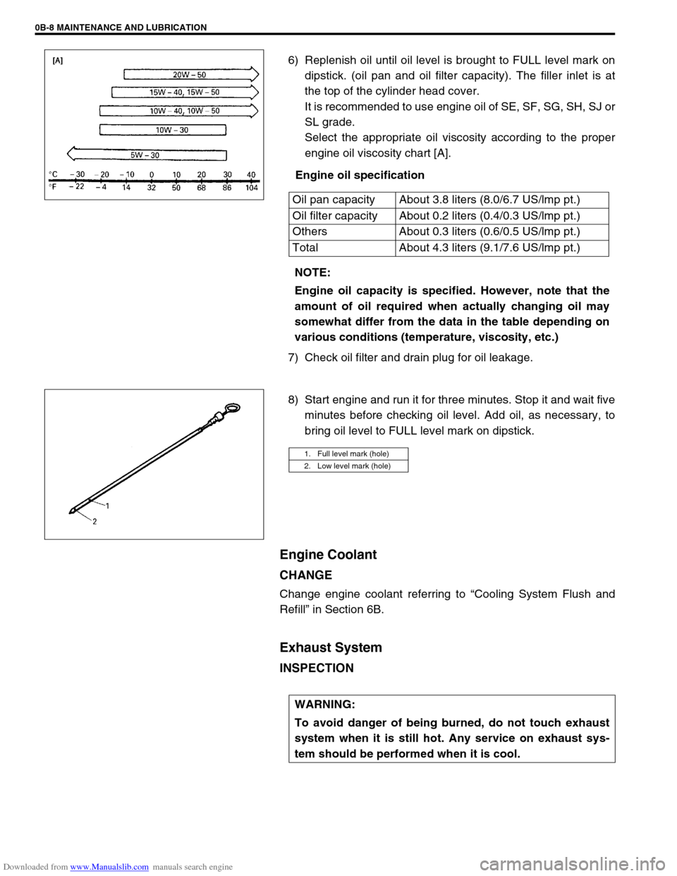
Select the appropriate oil viscosity according to the proper
engine oil viscosity chart [A].
Engine oil specification
7) Check oil filter and drain plug for oil leakage.
8) Start engine and run it for three minutes. Stop it and wait five
minutes before checking oil level. Add oil, as necessary, to
bring oil level to FULL level mark on dipstick.
Engine Coolant
CHANGE
Change engine coolant referring to “Cooling System Flush and
Refill” in Section 6B.
Exhaust System
INSPECTION
Oil pan capacity About 3.8 liters (8.0/6.7 US/lmp pt.)
Oil filter capacity About 0.2 liters (0.4/0.3 US/lmp pt.)
Others About 0.3 liters (0.6/0.5 US/lmp pt.)
Total About 4.3 liters (9.1/7.6 US/lmp pt.)
NOTE:
Engine oil capacity is specified. However, note that the
amount of oil required when actually changing oil may
somewhat differ from the data in the table depending on
various conditions (temperature, viscosity, etc.)
1. Full level mark (hole)
2. Low level mark (hole)
WARNING:
To avoid danger of being burned, do not touch exhaust
system when it is still hot. Any service on exhaust sys-
tem should be performed when it is cool.
Page 43 of 687
Downloaded from www.Manualslib.com manuals search engine 0B-12 MAINTENANCE AND LUBRICATION
Brake Drums and Shoes
INSPECTION
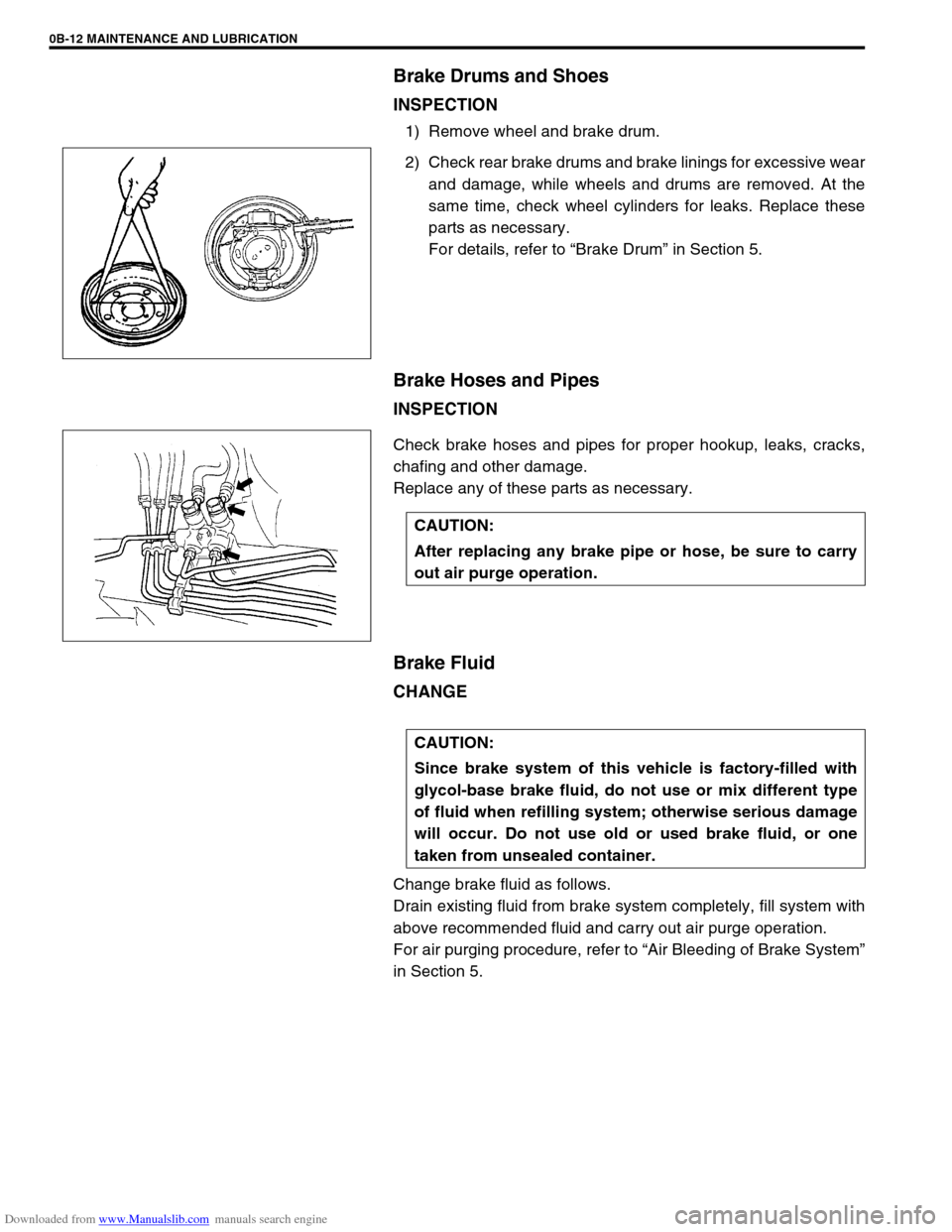
1) Remove wheel and brake drum.
2) Check rear brake drums and brake linings for excessive wear
and damage, while wheels and drums are removed. At the
same time, check wheel cylinders for leaks. Replace these
parts as necessary.
For details, refer to “Brake Drum” in Section 5.
Brake Hoses and Pipes
INSPECTION
Check brake hoses and pipes for proper hookup, leaks, cracks,
chafing and other damage.
Replace any of these parts as necessary.
Brake Fluid
CHANGE
Change brake fluid as follows.
Drain existing fluid from brake system completely, fill system with
above recommended fluid and carry out air purge operation.
For air purging procedure, refer to “Air Bleeding of Brake System”
in Section 5.
CAUTION:
After replacing any brake pipe or hose, be sure to carry
out air purge operation.
CAUTION:
Since brake system of this vehicle is factory-filled with
glycol-base brake fluid, do not use or mix different type
of fluid when refilling system; otherwise serious damage
will occur. Do not use old or used brake fluid, or one
taken from unsealed container.
Page 97 of 687
Downloaded from www.Manualslib.com manuals search engine 1B-36 AIR CONDITIONING (OPTIONAL)
INSTALLATION
Reverse removal procedure to install cooling unit, and then noting
the following instructions.
If A/C evaporator thermistor removed, its should be rein-
stalled in original position.
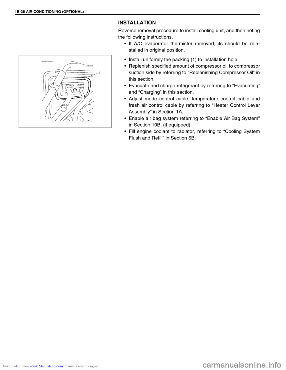
Install uniformly the packing (1) to installation hole.
Replenish specified amount of compressor oil to compressor
suction side by referring to “Replenishing Compressor Oil” in
this section.
Evacuate and charge refrigerant by referring to “Evacuating”
and “Charging” in this section.
Adjust mode control cable, temperature control cable and
fresh air control cable by referring to “Heater Control Lever
Assembly” in Section 1A.
Enable air bag system referring to “Enable Air Bag System”
in Section 10B. (if equipped)
Fill engine coolant to radiator, referring to “Cooling System
Flush and Refill” in Section 6B.
Page 207 of 687

Downloaded from www.Manualslib.com manuals search engine 3D-34 FRONT SUSPENSION
4) Install axle shaft (2) to front axle housing (1) (for 4WD).
5) Install knuckle to front axle housing. For details, refer to
“Steering Knuckle / Wheel Spindle” in this section.
6) Refill front axle (differential) housing with new specified gear
oil (for 4WD). Refer to “Maintenance Service” in Section 7E
for refill.
7) After servicing, check that no oil leakage exists.
Steering Knuckle Seal
REMOVAL
1) Hoist vehicle.
2) Remove knuckle seal cover bolts and seal cover (1).
3) Cut oil seal in place with scissors or knife, and take it off.
INSTALLATION
1) Cut replacement oil seal at one place with scissors or a
knife.
Page 216 of 687

Downloaded from www.Manualslib.com manuals search engine FRONT SUSPENSION 3D-43
17) Tighten lateral rod (1) mounting bolt and nut to specified
torque.
Tightening torque
Lateral rod bolt and nut
(a) : 90 N·m (9.0 kg-m, 65.0 lb-ft)
18) Tighten right and left shock absorber lower mounting nuts
and leading arm mounting nuts to specified torque.
Tightening torque
Shock absorber lower nuts and leading arm nuts
(a) : 90 N·m (9.0 kg-m, 65.0 lb-ft)
19) Refill front axle (differential) housing with new specified gear
oil. Refer to “Maintenance Service” in Section 7E for refill.
20) Confirm front end (wheel) alignment referring to “Preliminary
Checks Prior to Adjusting Front Alignment” in Section 3A. NOTE:
When tightening bolt and nut, be sure that vehicle is off
hoist and in non loaded condition.
NOTE:
When tightening these nuts, be sure that vehicle is off
hoist and in non loaded condition.
1. Shock absorber
2. Leading arm
Page 224 of 687

Downloaded from www.Manualslib.com manuals search engine REAR SUSPENSION 3E-5
Check wheel bearings for wear. When measuring thrust
play, apply a dial gauge to axle shaft center after removing
wheel center cap from wheel disc.
When measurement exceeds limit, replace bearing.
Rear wheel bearing thrust play limit
: 0.8 mm (0.03 in.)
By rotating wheel actually, check wheel bearing for noise and
smooth rotation. If it is defective, replace bearing.
On-Vehicle Service
Rear Shock Absorber
The shock absorber is non-adjustable, non-refillable, and cannot be disassembled. The only service the shock
absorber requires is replacement when it has lost its resistance, is damaged, or leaking fluid.
REMOVAL
1) Hoist vehicle.
2) Support rear axle housing (1) by using floor jack (2) to pre-
vent it from lowering.
WARNING:
When discarding shock absorber, be sure to refer to instructions in “Rear Shock Absorber Check” in
this section for proper procedure as it is gas sealed type.
Page 235 of 687
Downloaded from www.Manualslib.com manuals search engine 3E-16 REAR SUSPENSION
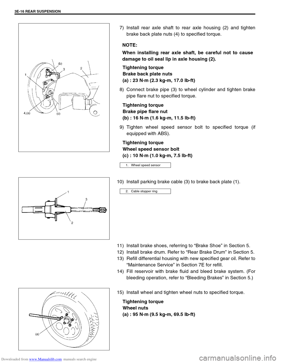
7) Install rear axle shaft to rear axle housing (2) and tighten
brake back plate nuts (4) to specified torque.
Tightening torque
Brake back plate nuts
(a) : 23 N·m (2.3 kg-m, 17.0 lb-ft)
8) Connect brake pipe (3) to wheel cylinder and tighten brake
pipe flare nut to specified torque.
Tightening torque
Brake pipe flare nut
(b) : 16 N·m (1.6 kg-m, 11.5 lb-ft)
9) Tighten wheel speed sensor bolt to specified torque (if
equipped with ABS).
Tightening torque
Wheel speed sensor bolt
(c) : 10 N·m (1.0 kg-m, 7.5 lb-ft)
10) Install parking brake cable (3) to brake back plate (1).
11) Install brake shoes, referring to “Brake Shoe” in Section 5.
12) Install brake drum. Refer to “Rear Brake Drum” in Section 5.
13) Refill differential housing with new specified gear oil. Refer to
“Maintenance Service” in Section 7E for refill.
14) Fill reservoir with brake fluid and bleed brake system. (For
bleeding operation, refer to “Bleeding Brakes” in Section 5.)
15) Install wheel and tighten wheel nuts to specified torque.
Tightening torque
Wheel nuts
(a) : 95 N·m (9.5 kg-m, 69.5 lb-ft) NOTE:
When installing rear axle shaft, be careful not to cause
damage to oil seal lip in axle housing (2).
1. Wheel speed sensor
2. Cable stopper ring
Page 265 of 687

Downloaded from www.Manualslib.com manuals search engine 5-4 BRAKES
Diagnosis
Road Testing Brakes
Brakes should be tested on dry, clean, smooth and reasonably level roadway which is not crowned. Road test
brakes by making brake applications with both light and heavy pedal forces at various speeds to determine if the
vehicle stops evenly and effectively.
Also drive vehicle to see if it leads to one side or the other without brake application. If it does, check the tire
pressure, front end alignment and front suspension attachments for looseness. See diagnosis table for other
causes.
Brake Fluid Leaks
Check the master cylinder fluid levels. While a slight drop in reservoir level does result from normal lining wear,
an abnormally low level indicates a leak in the system. In such a case, check the entire brake system for leak-
age. If even a slight evidence of leakage is noted, the cause should be corrected or defective parts should be
replaced.
If fluid level is lower than the minimum level of reservoir, refilling is necessary. Fill reservoir with specified brake
fluid.
Brake fluid: Refer to reservoir tank cap.
Substandard or Contaminated Brake Fluid
Improper brake fluid, mineral oil or water in the fluid may cause the brake fluid to boil or the rubber components
in the hydraulic system to deteriorate.
If primary piston cups are swollen, then rubber parts have deteriorated. This deterioration may also be evi-
denced by swollen wheel cylinder piston cups on the drum brake wheels.
If deterioration of rubber is evident, disassemble all hydraulic parts and wash with alcohol. Dry these parts with
compressed air before assembly to keep alcohol out of the system. Replace all rubber parts in the system,
including hoses. Also, when working on the brake mechanisms, check for fluid on the linings. If excessive fluid is
found, replace the linings.
If master cylinder piston seals are satisfactory, check for leakage or excessive heat conditions. If condition is not
found, drain fluid, flush with brake fluid, refill and bleed the system.
The system must be flushed if there is any doubt as to the grade of fluid in the system or if fluid has been used
which contained parts that have been subjected to contaminated fluid.CAUTION:
Since brake system of this vehicle is factory-filled with brake fluid indicated on reservoir tank cap, do
not use or mix different type of fluid when refilling; otherwise serious damage will occur.
Do not use old or used brake fluid, or any fluid from a unsealed container.
Page 272 of 687
Downloaded from www.Manualslib.com manuals search engine BRAKES 5-11
Rear Drum Brake Shoe Adjustment
Rear brake has self-adjusting mechanism but it does require
adjustment for proper drum to shoe clearance when brake shoe
has been replaced or brake drum has been removed for some
other service.
Adjustment is automatically accomplished by depressing brake
pedal about 30 times with approximately 30 kg (66 Ibs) load after
all parts are installed.
Then check brake drum for dragging and brake system for proper
performance. After lowering vehicle from hoist, brake test should
be performed.
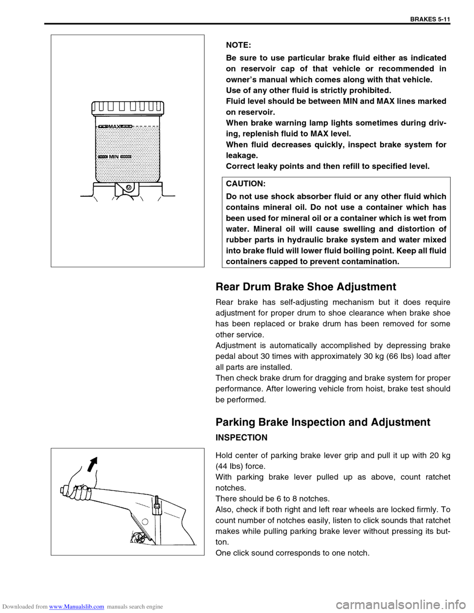
Parking Brake Inspection and Adjustment
INSPECTION
Hold center of parking brake lever grip and pull it up with 20 kg
(44 Ibs) force.
With parking brake lever pulled up as above, count ratchet
notches.
There should be 6 to 8 notches.
Also, check if both right and left rear wheels are locked firmly. To
count number of notches easily, listen to click sounds that ratchet
makes while pulling parking brake lever without pressing its but-
ton.
One click sound corresponds to one notch.NOTE:
Be sure to use particular brake fluid either as indicated
on reservoir cap of that vehicle or recommended in
owner’s manual which comes along with that vehicle.
Use of any other fluid is strictly prohibited.
Fluid level should be between MIN and MAX lines marked
on reservoir.
When brake warning lamp lights sometimes during driv-
ing, replenish fluid to MAX level.
When fluid decreases quickly, inspect brake system for
leakage.
Correct leaky points and then refill to specified level.
CAUTION:
Do not use shock absorber fluid or any other fluid which
contains mineral oil. Do not use a container which has
been used for mineral oil or a container which is wet from
water. Mineral oil will cause swelling and distortion of
rubber parts in hydraulic brake system and water mixed
into brake fluid will lower fluid boiling point. Keep all fluid
containers capped to prevent contamination.