Eps SUZUKI JIMNY 2005 3.G Service User Guide
[x] Cancel search | Manufacturer: SUZUKI, Model Year: 2005, Model line: JIMNY, Model: SUZUKI JIMNY 2005 3.GPages: 687, PDF Size: 13.38 MB
Page 422 of 687

Downloaded from www.Manualslib.com manuals search engine ENGINE GENERAL INFORMATION AND DIAGNOSIS 6-65
6) Repeat above steps 5) 4 times.
7) Increase vehicle speed to about 50 mph (80 km/h) in 3rd gear or 2 range.
8) Release accelerator pedal and with engine brake applied, keep vehicle coasting (fuel cut condition) for
10sec. or more.
9) Stop vehicle (don’t turn ignition switch OFF) and run engine at idle for 2 min. After this step 9), if “Oxygen
Sensor Monitoring TEST COMPLETED” is displayed in “READINESS TESTS” mode and DTC is not dis-
played in “DTC” mode, confirmation test is completed.
If “TEST NOT COMPLTD” is still being displayed, proceed to next step 10).
10) Drive vehicle under usual driving condition for 10 min. (or vehicle is at a stop and run engine at idle for 10
min. or longer)
11) Stop vehicle (don’t turn ignition switch OFF). Confirm test results according to “Test Result Confirmation
Flow Table” in “DTC CONFIRMATION PROCEDURE” of DTC P0420.
INSPECTION
*Usual driving : Driving at 30 – 40 mph, 50 – 60 km/h including short stop according to traffic signal. (under driving condition other than high-load, high-engine
speed, rapid accelerating and decelerating)
Step Action Yes No
1Was “Engine Diag. Flow Table” performed? Go to Step 2. Go to “Engine Diag. Flow
Table”.
2 Check exhaust system for leakage, loose con-
nection and damage.
Is it good condition?Go to Step 3. Repair or replace.
3 Check HO2S-2 and Its Circuit.
Was HO2S-2 output voltage indicated on scan
tool in step 3) of DTC confirmation test less
than 1.275 V?Go to Step 4.“B/Bl” or “W” circuit open
or HO2S-2 malfunction.
4 Check Short Term Fuel Trim.
Did short term fuel trim very within –20 – + 20%
range in step 3) of DTC confirmation test?Check “W” and “B/Bl” wire
for open and short, and
connection for poor con-
nection. If wire and con-
nection are OK, replace
HO2S-2.Check fuel system. Go to
DTC P0171 / P0172 Diag.
Flow Table.
Page 427 of 687

Downloaded from www.Manualslib.com manuals search engine 6-70 ENGINE GENERAL INFORMATION AND DIAGNOSIS
5 Check Fuel Injectors and Circuit.
1) Using sound scope (4) or such, check operating
sound of each injector (5) when engine is run-
ning. Cycle of operating sound should vary
according to engine speed. See Fig. 3.
If no sound or an unusual sound is heard, check
injector circuit (wire or coupler) or injector.
2) Turn ignition switch OFF and disconnect a fuel
injector connector.
3) Check for proper connection to fuel injector at
each terminal.
4) If OK, then check injector resistance.
See Fig. 4.
Injector resistance
11.3 – 13.8 ohm at 20 °C (68 °F)
5) Carry out steps 1) and 3) on each injector.
6) Check each injector for injected fuel volume
referring to Section 6E. See Fig. 5.
Injected fuel volume
43 – 47 cc/15 sec (1.45/1.51 – 1.58/1.65 US/
Imp.oz/15 sec)
7) Check each injector for fuel leakage after injec-
tor closed.
Fuel leakage
Less than 1 drop / min. (1)
Is check result in step 1) and 3) to 7) satisfactory?Go to Step 6. Check injector circuit or
replace fuel injector(s).
6 Check EVAP Canister Purge Valve.
1) Disconnect purge hose (2) from EVAP canister.
2) Place finger against the end of disconnected
hose.
3) Check that vacuum is not felt there when
engine is cool and running at idle. See Fig. 6.
Is vacuum felt?Check EVAP control
system (See Section
6E).Go to Step 7.
7 Check intake manifold absolute pressure sensor for
performance (See step 4) of DTC P0105 (No.11)
Diag. Flow Table).
Is it in good condition?Go to Step 8. Repair or replace.
8 Check engine coolant temp. sensor for perfor-
mance (See Section 6E).
Is it in good condition?Go to Step 9. Replace engine coolant
temp. sensor.
9 Check intake air temp. sensor for performance
(See Section 6E).
Is it in good condition?Go to Step 10. Replace intake air temp.
sensor.
10 Check throttle position sensor for performance
(See step 5) of DTC P0121 Diag. Flow Table).
Is it in good condition?Go to Step 11. Replace throttle position
sensor.
11 Check PCV valve for valve clogging
(See Section 6E).
Is it good condition?Substitute a known-
good ECM and recheck.Replace PCV valve. Step Action Yes No
Page 431 of 687

Downloaded from www.Manualslib.com manuals search engine 6-74 ENGINE GENERAL INFORMATION AND DIAGNOSIS
3 Check Ignition System.
1) Remove spark plugs and check them for;
Air gap : 1.0 – 1.1 mm (0.040 – 0.043 in.) See Fig. 1.
Carbon deposits / Insulator damage / Plug type
If abnormality is found, adjust, clean or replace by
referring to Section 6F. (See CAUTION)
2) Disconnect all injector connectors. See Fig. 2.
3) Connect spark plugs to high tension cords and then
ground spark plugs.
4) Crank engine and check that each spark plug sparks.
Are above check results satisfactory?Go to Step 4. Check ignition sys-
tem parts (Refer to
Section 6F).
4 Check Fuel Pressure (Refer to Section 6E for details).
1) Release fuel pressure from fuel feed line.
2) Install fuel pressure gauge. See Fig. 3.
3) Check fuel pressure.
Fuel pressure specification
With fuel pump operating and engine at stop :
270 – 310 kPa, 2.7 – 3.1 kg/cm
2, 38.4 – 44.0 psi.
At specified idle speed :
210 – 260 kPa, 2.1 – 2.6 kg/cm
2, 29.8 – 37.0 psi.
Is measured value as specified?Go to Step 5. Go to Diag. Flow
Table B-3 fuel pres-
sure check.
5 Check Fuel Injectors and Circuit.
1) sing sound scope (1) or such, check operating sound
of each injector (2) when engine is running. Cycle of
operating sound should very according to engine
speed. See Fig 4.
If no sound or an unusual sound is heard, check
injector circuit (wire or coupler) or injector.
2) Turn ignition switch OFF and disconnect a fuel injec-
tor connector.
3) Check for proper connection to fuel injector at each
terminal.
4) If OK, then check injector resistance. See Fig. 5.
Injector resistance
11.3 – 13.8 ohm at 20 °C (68 °F)
5) Carry out steps 1) and 3) on each injector.
6) Check each injector for injected fuel volume referring
to Section 6E. See Fig. 6.
Injected fuel volume
43 – 47 cc/15 sec (1.45/1.51 – 1.58/1.65 US/Imp. oz/
15 sec)
7) Check each injector for fuel leakage after injector
closed.
Fuel leakage
Less than 1 drop/min.
Is check result in step 1) and 3) to 7) satisfactory?Go to Step 6. Check injector cir-
cuit or replace fuel
injector(s).
6 Check PCV valve for clogging (See Section 6E).
Is it in good condition?Go to Step 7. Replace PCV
valve. Step Action Yes No
Page 447 of 687

Downloaded from www.Manualslib.com manuals search engine 6-90 ENGINE GENERAL INFORMATION AND DIAGNOSIS
Test Result Confirmation Flow Table
INSPECTION
Step Action Yes No
1 Check DTC in “DTC” mode and pending DTC in
“ON BOARD TEST” or “PENDING DTC” mode.
Is DTC or pending DTC displayed?Proceed to applicable
DTC Diag. Flow Table.Go to Step 2.
2 Set scan tool to “READINESS TESTS” mode
and check if testing has been completed.
Is test completed?No DTC is detected (con-
firmation test is com-
pleted).Repeat DTC confirmation
procedure.
Step Action Yes No
1Was “Engine Diag. Flow Table” performed? Go to Step 2. Go to “Engine Diag. Flow
Table”.
2 Check Short Term Fuel Trim.
Did short term fuel trim vary within –20 % –
+20 % range in step 3) of DTC confirmation
test?Go to Step 3. Check fuel system.
Go to DTC P0171/P0172
Diag. Flow Table.
3 Check HO2S-2 for Output Voltage.
Perform steps 1) through 9) of DTC confirma-
tion procedure for DTC P0136 (HO2S-2 mal-
function) and check output voltage of HO2S-2
then.
Is over 0.6 V and below 0.3 V indicated?Replace three way cata-
lytic converter.Check “W” and “B/Bl”
wires for open and short,
and connections for poor
connection.
If wires and connections
are OK, replace HO2S-2.
Page 486 of 687
Downloaded from www.Manualslib.com manuals search engine ENGINE MECHANICAL (M13 ENGINE) 6A1-5
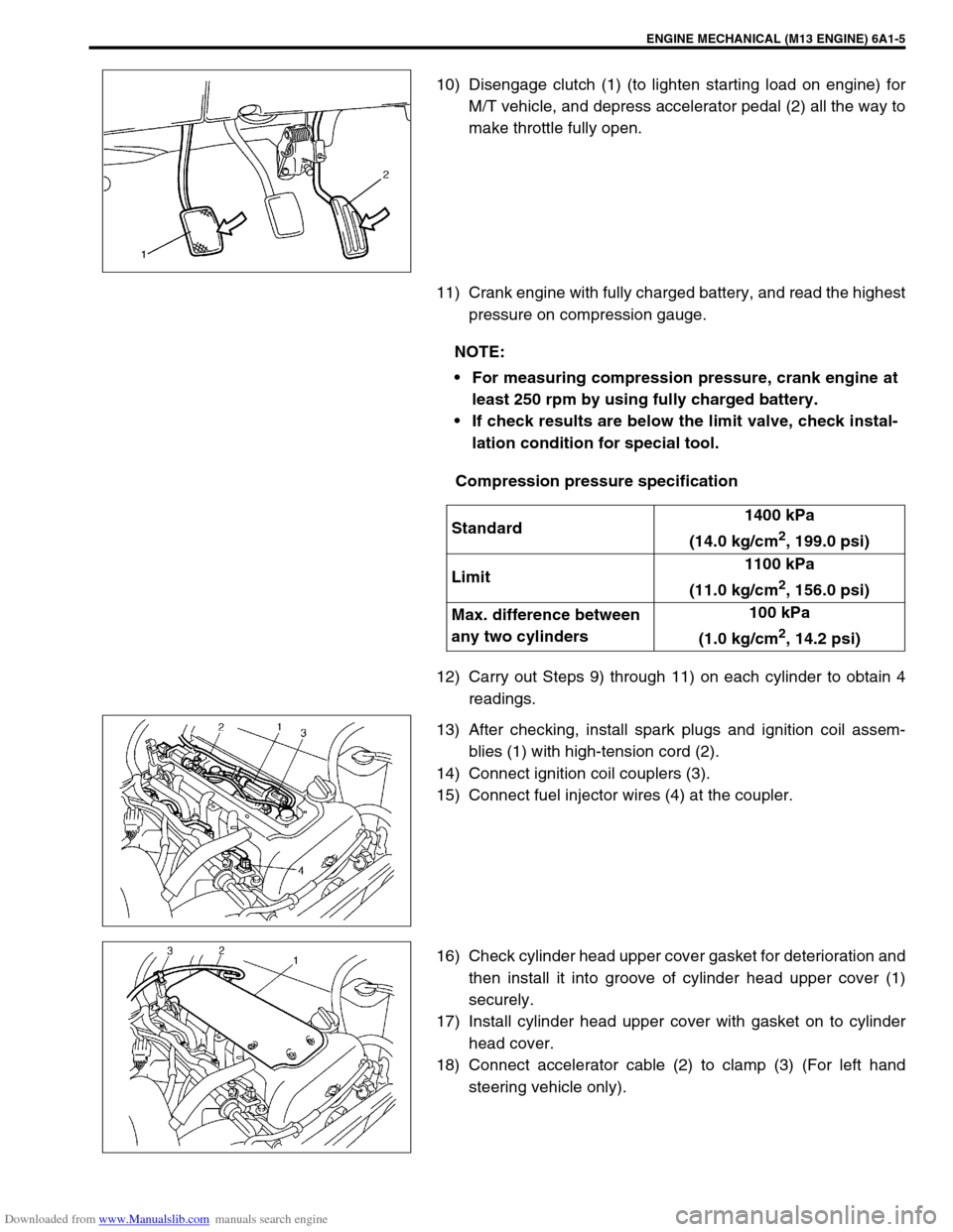
10) Disengage clutch (1) (to lighten starting load on engine) for
M/T vehicle, and depress accelerator pedal (2) all the way to
make throttle fully open.
11) Crank engine with fully charged battery, and read the highest
pressure on compression gauge.
Compression pressure specification
12) Carry out Steps 9) through 11) on each cylinder to obtain 4
readings.
13) After checking, install spark plugs and ignition coil assem-
blies (1) with high-tension cord (2).
14) Connect ignition coil couplers (3).
15) Connect fuel injector wires (4) at the coupler.
16) Check cylinder head upper cover gasket for deterioration and
then install it into groove of cylinder head upper cover (1)
securely.
17) Install cylinder head upper cover with gasket on to cylinder
head cover.
18) Connect accelerator cable (2) to clamp (3) (For left hand
steering vehicle only).
NOTE:
For measuring compression pressure, crank engine at
least 250 rpm by using fully charged battery.
If check results are below the limit valve, check instal-
lation condition for special tool.
Standard1400 kPa
(14.0 kg/cm
2, 199.0 psi)
Limit1100 kPa
(11.0 kg/cm
2, 156.0 psi)
Max. difference between
any two cylinders100 kPa
(1.0 kg/cm
2, 14.2 psi)
Page 522 of 687
Downloaded from www.Manualslib.com manuals search engine ENGINE MECHANICAL (M13 ENGINE) 6A1-41
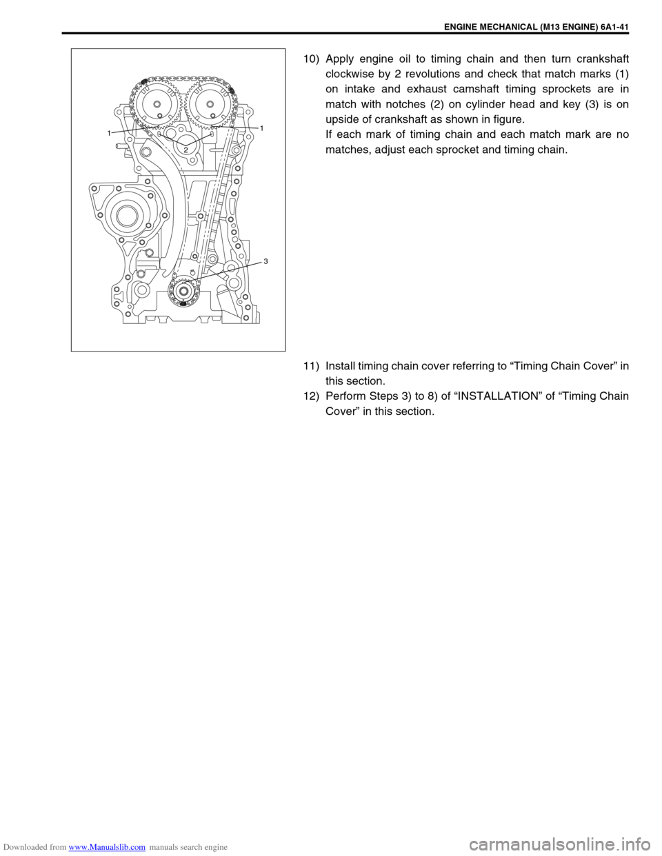
10) Apply engine oil to timing chain and then turn crankshaft
clockwise by 2 revolutions and check that match marks (1)
on intake and exhaust camshaft timing sprockets are in
match with notches (2) on cylinder head and key (3) is on
upside of crankshaft as shown in figure.
If each mark of timing chain and each match mark are no
matches, adjust each sprocket and timing chain.
11) Install timing chain cover referring to “Timing Chain Cover” in
this section.
12) Perform Steps 3) to 8) of “INSTALLATION” of “Timing Chain
Cover” in this section.
21
1
3
Page 533 of 687
Downloaded from www.Manualslib.com manuals search engine 6A1-52 ENGINE MECHANICAL (M13 ENGINE)
DISASSEMBLY
1) For ease in servicing cylinder head, remove intake manifold,
injectors and exhaust manifold from cylinder head.
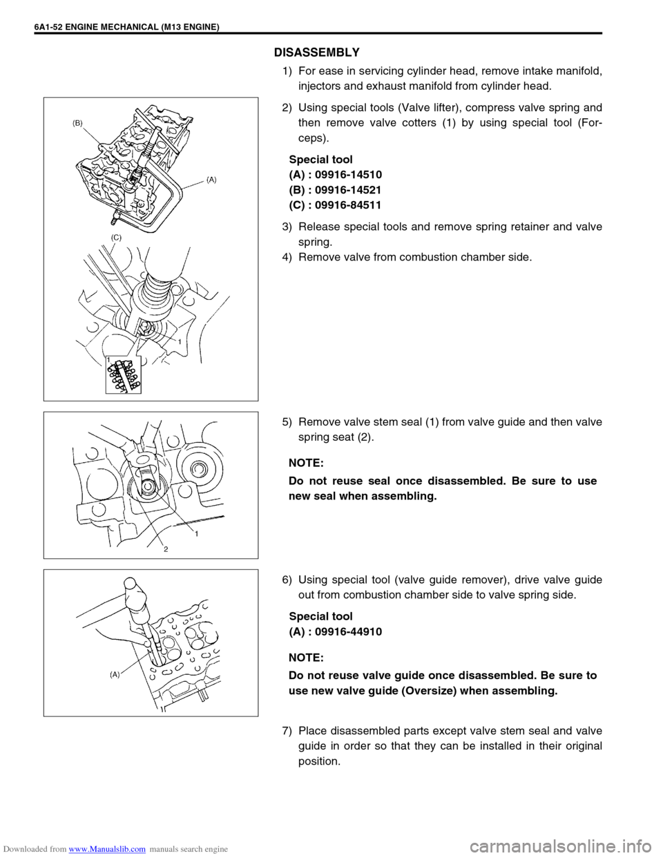
2) Using special tools (Valve lifter), compress valve spring and
then remove valve cotters (1) by using special tool (For-
ceps).
Special tool
(A) : 09916-14510
(B) : 09916-14521
(C) : 09916-84511
3) Release special tools and remove spring retainer and valve
spring.
4) Remove valve from combustion chamber side.
5) Remove valve stem seal (1) from valve guide and then valve
spring seat (2).
6) Using special tool (valve guide remover), drive valve guide
out from combustion chamber side to valve spring side.
Special tool
(A) : 09916-44910
7) Place disassembled parts except valve stem seal and valve
guide in order so that they can be installed in their original
position.
NOTE:
Do not reuse seal once disassembled. Be sure to use
new seal when assembling.
NOTE:
Do not reuse valve guide once disassembled. Be sure to
use new valve guide (Oversize) when assembling.
Page 536 of 687
Downloaded from www.Manualslib.com manuals search engine ENGINE MECHANICAL (M13 ENGINE) 6A1-55
Valve seat repair:
A valve seat not producing a uniform contact with its valve or
showing width of seating contact that is out of specified
range must be repaired by regrinding or by cutting and
regrinding and finished by lapping.
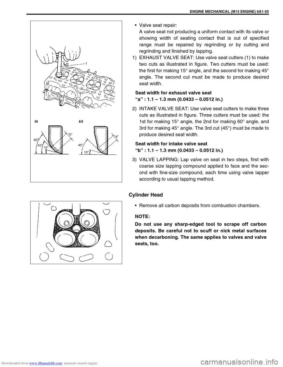
1) EXHAUST VALVE SEAT: Use valve seat cutters (1) to make
two cuts as illustrated in figure. Two cutters must be used:
the first for making 15° angle, and the second for making 45°
angle. The second cut must be made to produce desired
seat width.
Seat width for exhaust valve seat
“a” : 1.1 – 1.3 mm (0.0433 – 0.0512 in.)
2) INTAKE VALVE SEAT: Use valve seat cutters to make three
cuts as illustrated in figure. Three cutters must be used: the
1st for making 15° angle, the 2nd for making 60° angle, and
3rd for making 45° angle. The 3rd cut (45°) must be made to
produce desired seat width.
Seat width for intake valve seat
“b” : 1.1 – 1.3 mm (0.0433 – 0.0512 in.)
3) VALVE LAPPING: Lap valve on seat in two steps, first with
coarse size lapping compound applied to face and the sec-
ond with fine-size compound, each time using valve lapper
according to usual lapping method.
Cylinder Head
Remove all carbon deposits from combustion chambers.
NOTE:
Do not use any sharp-edged tool to scrape off carbon
deposits. Be careful not to scuff or nick metal surfaces
when decarboning. The same applies to valves and valve
seats, too.
Page 555 of 687
Downloaded from www.Manualslib.com manuals search engine 6A1-74 ENGINE MECHANICAL (M13 ENGINE)
a) For right hand steering vehicle:
With hose connected, detach A/C compressor from its
bracket.
b) For left hand steering vehicle:
i) Recover refrigerant from refrigeration system using recov-
ery and recycling equipment.
ii) Disconnect magnet clutch lead wire.
iii) Remove suction pipe and disconnect discharge pipe from
A/C compressor.
iv) Remove A/C compressor from its bracket.
When servicing above steps, refer to “Compressor” in Section 1B.
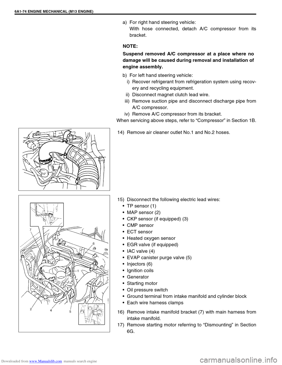
14) Remove air cleaner outlet No.1 and No.2 hoses.
15) Disconnect the following electric lead wires:
TP sensor (1)
MAP sensor (2)
CKP sensor (if equipped) (3)
CMP sensor
ECT sensor
Heated oxygen sensor
EGR valve (if equipped)
IAC valve (4)
EVAP canister purge valve (5)
Injectors (6)
Ignition coils
Generator
Starting motor
Oil pressure switch
Ground terminal from intake manifold and cylinder block
Each wire harness clamps
16) Remove intake manifold bracket (7) with main harness from
intake manifold.
17) Remove starting motor referring to “Dismounting” in Section
6G. NOTE:
Suspend removed A/C compressor at a place where no
damage will be caused during removal and installation of
engine assembly.
Page 576 of 687
Downloaded from www.Manualslib.com manuals search engine ENGINE MECHANICAL (M13 ENGINE) 6A1-95
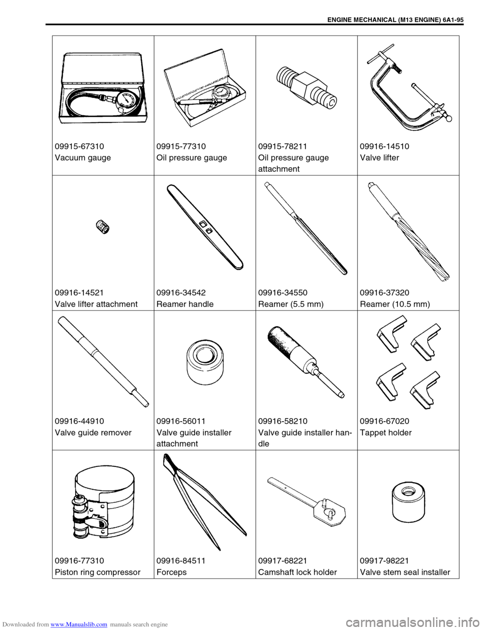
09915-67310 09915-77310 09915-78211 09916-14510
Vacuum gauge Oil pressure gauge Oil pressure gauge
attachmentValve lifter
09916-14521 09916-34542 09916-34550 09916-37320
Valve lifter attachment Reamer handle Reamer (5.5 mm) Reamer (10.5 mm)
09916-44910 09916-56011 09916-58210 09916-67020
Valve guide remover Valve guide installer
attachmentValve guide installer han-
dleTappet holder
09916-77310 09916-84511 09917-68221 09917-98221
Piston ring compressor Forceps Camshaft lock holder Valve stem seal installer