abs SUZUKI JIMNY 2005 3.G Service User Guide
[x] Cancel search | Manufacturer: SUZUKI, Model Year: 2005, Model line: JIMNY, Model: SUZUKI JIMNY 2005 3.GPages: 687, PDF Size: 13.38 MB
Page 155 of 687
Downloaded from www.Manualslib.com manuals search engine 3C-2 STEERING WHEEL AND COLUMN
General Description
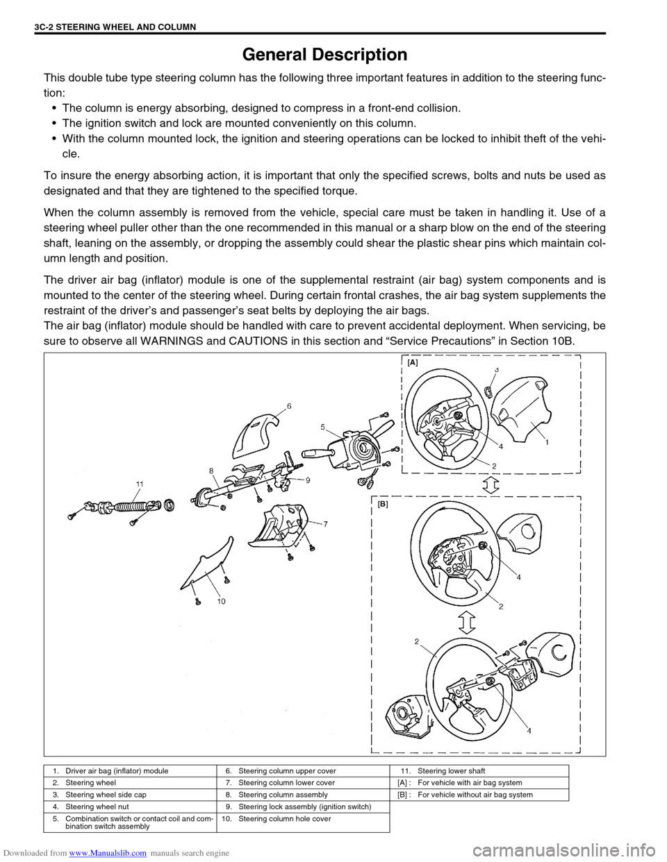
This double tube type steering column has the following three important features in addition to the steering func-
tion:
The column is energy absorbing, designed to compress in a front-end collision.
The ignition switch and lock are mounted conveniently on this column.
With the column mounted lock, the ignition and steering operations can be locked to inhibit theft of the vehi-
cle.
To insure the energy absorbing action, it is important that only the specified screws, bolts and nuts be used as
designated and that they are tightened to the specified torque.
When the column assembly is removed from the vehicle, special care must be taken in handling it. Use of a
steering wheel puller other than the one recommended in this manual or a sharp blow on the end of the steering
shaft, leaning on the assembly, or dropping the assembly could shear the plastic shear pins which maintain col-
umn length and position.
The driver air bag (inflator) module is one of the supplemental restraint (air bag) system components and is
mounted to the center of the steering wheel. During certain frontal crashes, the air bag system supplements the
restraint of the driver’s and passenger’s seat belts by deploying the air bags.
The air bag (inflator) module should be handled with care to prevent accidental deployment. When servicing, be
sure to observe all WARNINGS and CAUTIONS in this section and “Service Precautions” in Section 10B.
1. Driver air bag (inflator) module 6. Steering column upper cover 11. Steering lower shaft
2. Steering wheel 7. Steering column lower cover [A] : For vehicle with air bag system
3. Steering wheel side cap 8. Steering column assembly [B] : For vehicle without air bag system
4. Steering wheel nut 9. Steering lock assembly (ignition switch)
5. Combination switch or contact coil and com-
bination switch assembly10. Steering column hole cover
Page 174 of 687
Downloaded from www.Manualslib.com manuals search engine FRONT SUSPENSION 3D-1
6F1
6F2
6G
1A
6K
7A
7A1
3D
7F
8A
8A
8B
8C
8D
8E
9
10
10A
10B
SECTION 3D
FRONT SUSPENSION
CONTENTS
General Description ....................................... 3D-2
4WD Control System .................................... 3D-2
Diagnosis ........................................................ 3D-8
Diagnosis Table ........................................... 3D-8
4WD Controller and ITS Circuit Check ....... 3D-10
4WD Control System Check ...................... 3D-11
Stabilizer bar / bushing check ................ 3D-13
Shock Absorber and/or Coil Spring
Check ......................................................... 3D-14
Leading Arm / Lateral Rod / Steering
Knuckle Check ........................................... 3D-14
Leading Arm Bushing / Lateral Rod
Bushing Check ........................................... 3D-15
Kingpin / Kingpin Bearing Check ................ 3D-15
Barfield Joint Check ................................... 3D-15
Steering Knuckle Seal Check ..................... 3D-15
Wheel Disc, Nut and Bearing Check .......... 3D-16On-Vehicle Service ...................................... 3D-17
Stabilizer Bar / Bushings ............................ 3D-17
Front Shock Absorber ................................ 3D-19
Coil Spring ................................................. 3D-19
Bump Stopper and Spring Upper Seat ...... 3D-21
Wheel Hub / Bearing / Oil Seal .................. 3D-21
Steering Knuckle / Wheel Spindle.............. 3D-28
Front Axle Shaft / Oil Seal / Kingpin
Bearing Outer Race ................................... 3D-32
Steering Knuckle Seal................................ 3D-34
Lateral Rod ................................................ 3D-35
Leading Arm / Bushing............................... 3D-36
Front Axle Housing .................................... 3D-38
Tightening Torque Specifications .............. 3D-44
Required Service Material ........................... 3D-44
Special Tool .................................................. 3D-45
WARNING:
When hoisting vehicle, be sure to select the lifting point suitable for the service work referring to Sec-
tion 0A.
NOTE:
All front suspension fasteners are an important attaching part in that it could affect the performance
of vital parts and systems, and/or could result in major repair expense. They must be replaced with
one of the same part number or with an equivalent part if replacement becomes necessary. Do not
use a replacement part of lesser quality or substitute design. Torque values must be used as speci-
fied during reassembly to assure proper retention of this part.
Never attempt to heat, quench or straighten any front suspension part. Replace it with a new part or
damage to the part may result.
Page 175 of 687
Downloaded from www.Manualslib.com manuals search engine 3D-2 FRONT SUSPENSION
General Description
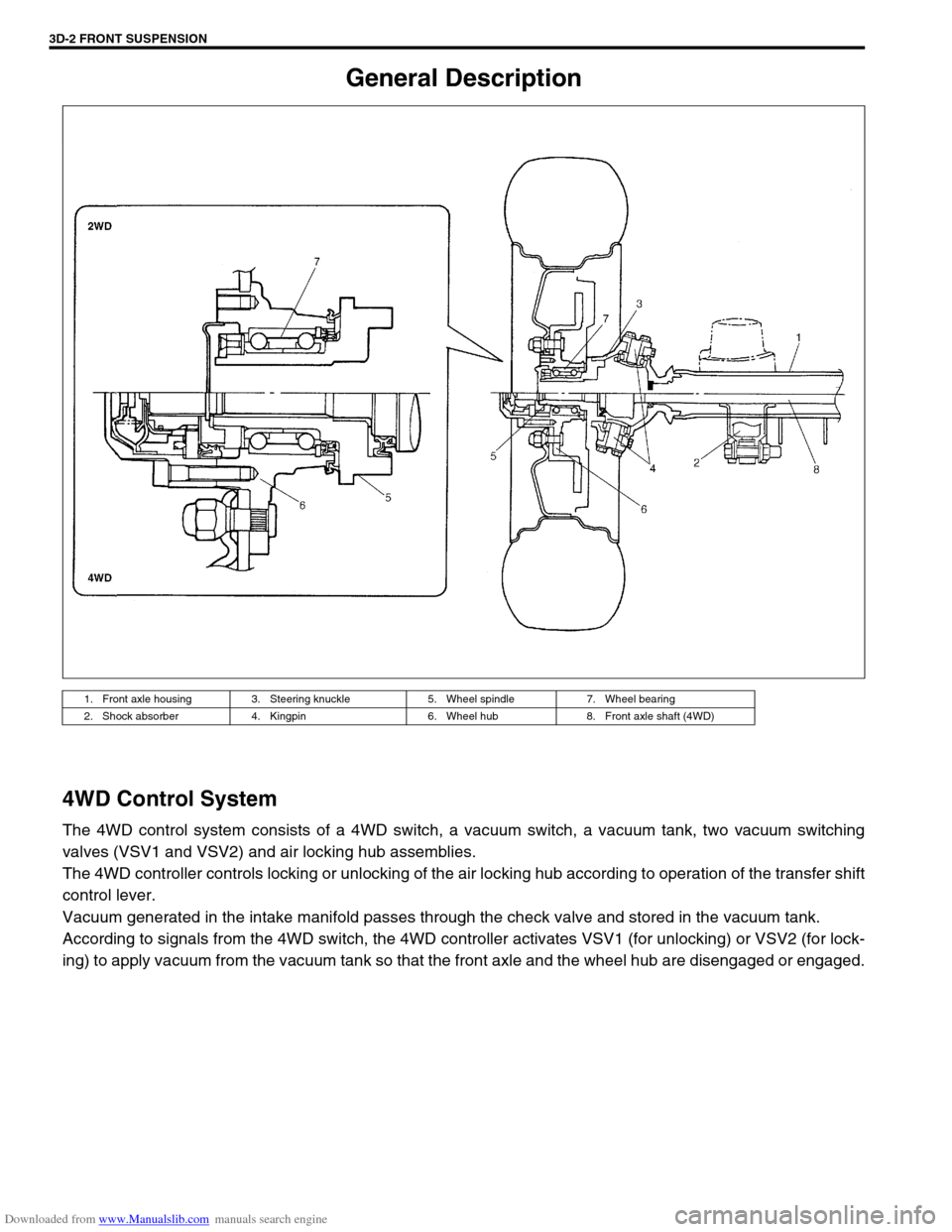
4WD Control System
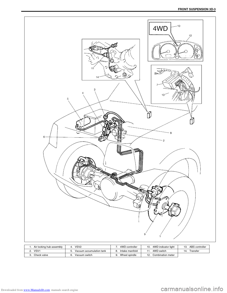
The 4WD control system consists of a 4WD switch, a vacuum switch, a vacuum tank, two vacuum switching
valves (VSV1 and VSV2) and air locking hub assemblies.
The 4WD controller controls locking or unlocking of the air locking hub according to operation of the transfer shift
control lever.
Vacuum generated in the intake manifold passes through the check valve and stored in the vacuum tank.
According to signals from the 4WD switch, the 4WD controller activates VSV1 (for unlocking) or VSV2 (for lock-
ing) to apply vacuum from the vacuum tank so that the front axle and the wheel hub are disengaged or engaged.
1. Front axle housing 3. Steering knuckle 5. Wheel spindle 7. Wheel bearing
2. Shock absorber 4. Kingpin 6. Wheel hub 8. Front axle shaft (4WD)
Page 176 of 687
Downloaded from www.Manualslib.com manuals search engine FRONT SUSPENSION 3D-3
1. Air locking hub assembly 4. VSV2 7. 4WD controller 10. 4WD indicator light 13. ABS controller
2. VSV1 5. Vacuum accumulation tank 8. Intake manifold 11. 4WD switch 14. Transfer
3. Check valve 6. Vacuum switch 9. Wheel spindle 12. Combination meter
Page 187 of 687

Downloaded from www.Manualslib.com manuals search engine 3D-14 FRONT SUSPENSION
Shock Absorber and/or Coil Spring Check
1) Inspect shock absorber for oil leakage. If shock absorber is
found faulty, replace it as an assembly unit, because it can
not be disassembled.
2) Shock absorber function check
Check and adjust tire pressures as specified.
Bounce body three or four times continuously by pushing
front end on the side with shock absorber to be checked.
Apply the same amount of force at each push and note
shock absorber resistance both when pushed and rebound-
ing.
Also, note how many times vehicle body rebounds before
coming to stop after hands are off. Do the same for shock
absorber on the other side.
Compare shock absorber resistance and number of rebound
on the right with those on the left.
And they must be equal in both. With proper shock absorber,
body should come to stop the moment hands are off or after
only one or two small rebounds. If shock absorbers are sus-
pected, compare them with known good vehicle or shock
absorber.
3) Inspect for damage or deformation.
4) Inspect for cracks or deformation in spring seat.
5) Inspect for deterioration of bump stopper.
6) Inspect shock absorber mount for wear, cracks or deforma-
tion.Replace any parts found defective in steps 2) – 6).
Leading Arm / Lateral Rod / Steering Knuckle
Check
Inspect for cracks, deformation or damage.
Page 192 of 687
Downloaded from www.Manualslib.com manuals search engine FRONT SUSPENSION 3D-19
Front Shock Absorber
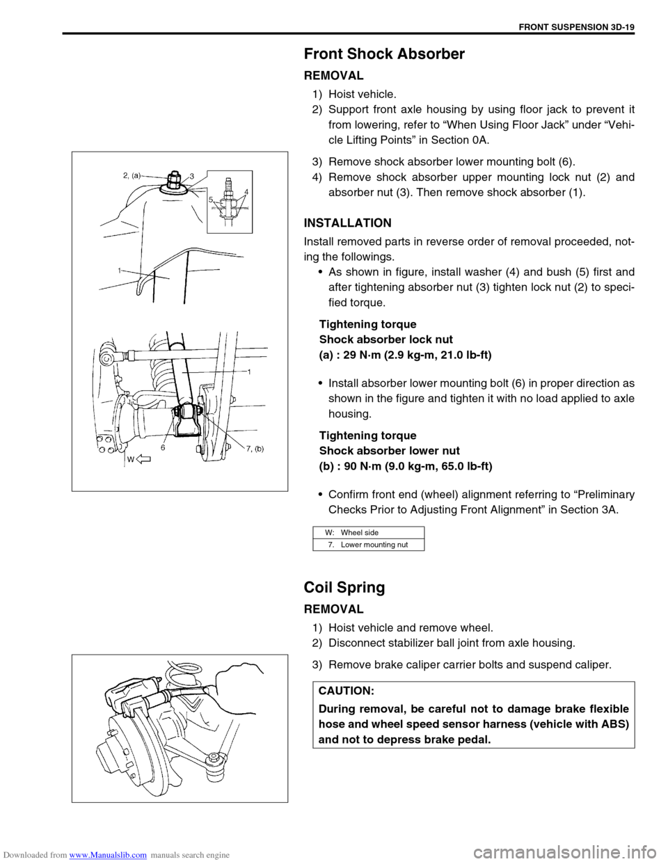
REMOVAL
1) Hoist vehicle.
2) Support front axle housing by using floor jack to prevent it
from lowering, refer to “When Using Floor Jack” under “Vehi-
cle Lifting Points” in Section 0A.
3) Remove shock absorber lower mounting bolt (6).
4) Remove shock absorber upper mounting lock nut (2) and
absorber nut (3). Then remove shock absorber (1).
INSTALLATION
Install removed parts in reverse order of removal proceeded, not-
ing the followings.
As shown in figure, install washer (4) and bush (5) first and
after tightening absorber nut (3) tighten lock nut (2) to speci-
fied torque.
Tightening torque
Shock absorber lock nut
(a) : 29 N·m (2.9 kg-m, 21.0 lb-ft)
Install absorber lower mounting bolt (6) in proper direction as
shown in the figure and tighten it with no load applied to axle
housing.
Tightening torque
Shock absorber lower nut
(b) : 90 N·m (9.0 kg-m, 65.0 lb-ft)
Confirm front end (wheel) alignment referring to “Preliminary
Checks Prior to Adjusting Front Alignment” in Section 3A.
Coil Spring
REMOVAL
1) Hoist vehicle and remove wheel.
2) Disconnect stabilizer ball joint from axle housing.
3) Remove brake caliper carrier bolts and suspend caliper.
W: Wheel side
7. Lower mounting nut
CAUTION:
During removal, be careful not to damage brake flexible
hose and wheel speed sensor harness (vehicle with ABS)
and not to depress brake pedal.
Page 193 of 687

Downloaded from www.Manualslib.com manuals search engine 3D-20 FRONT SUSPENSION
4) Support front axle housing by using floor jack.
5) Remove shock absorber lower mounting bolt (1).
6) Lower front axle housing (2) gradually as far down as where
coil spring (1) can be removed.
7) Remove coil spring (1).
INSTALLATION
Install removed parts in reverse order of removal procedures, not-
ing the followings.
1) Install coil spring (3).
2) Install absorber lower mounting bolt, refer to “Front Shock
Absorber” in this section.
3) Install caliper assembly and tighten caliper bolts to specified
torque.
Tightening torque
Brake caliper carrier bolts
(a) : 85 N·m (8.5 kg-m, 61.5 lb-ft)
4) Connect stabilizer ball joint to axle housing and tighten nut
referring to “Stabilizer Bar” in this section for tightening
torque specification. NOTE:
When supporting axle housing, it should be in non-load
condition.
NOTE:
Make sure that coil spring direction as shown.
When seating coil spring, mate spring end with
stepped part (4) of lower spring seat (2).
1. Front axle housing
U : Upper side
A : Small
B : Large
Page 194 of 687
Downloaded from www.Manualslib.com manuals search engine FRONT SUSPENSION 3D-21
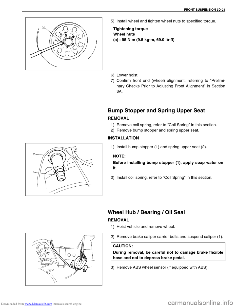
5) Install wheel and tighten wheel nuts to specified torque.
Tightening torque
Wheel nuts
(a) : 95 N·m (9.5 kg-m, 69.0 lb-ft)
6) Lower hoist.
7) Confirm front end (wheel) alignment, referring to “Prelimi-
nary Checks Prior to Adjusting Front Alignment” in Section
3A.
Bump Stopper and Spring Upper Seat
REMOVAL
1) Remove coil spring, refer to “Coil Spring” in this section.
2) Remove bump stopper and spring upper seat.
INSTALLATION
1) Install bump stopper (1) and spring upper seat (2).
2) Install coil spring, refer to “Coil Spring” in this section.
Wheel Hub / Bearing / Oil Seal
REMOVAL
1) Hoist vehicle and remove wheel.
2) Remove brake caliper carrier bolts and suspend caliper (1).
3) Remove ABS wheel sensor (if equipped with ABS).
NOTE:
Before installing bump stopper (1), apply soap water on
it.
CAUTION:
During removal, be careful not to damage brake flexible
hose and not to depress brake pedal.
Page 196 of 687
Downloaded from www.Manualslib.com manuals search engine FRONT SUSPENSION 3D-23
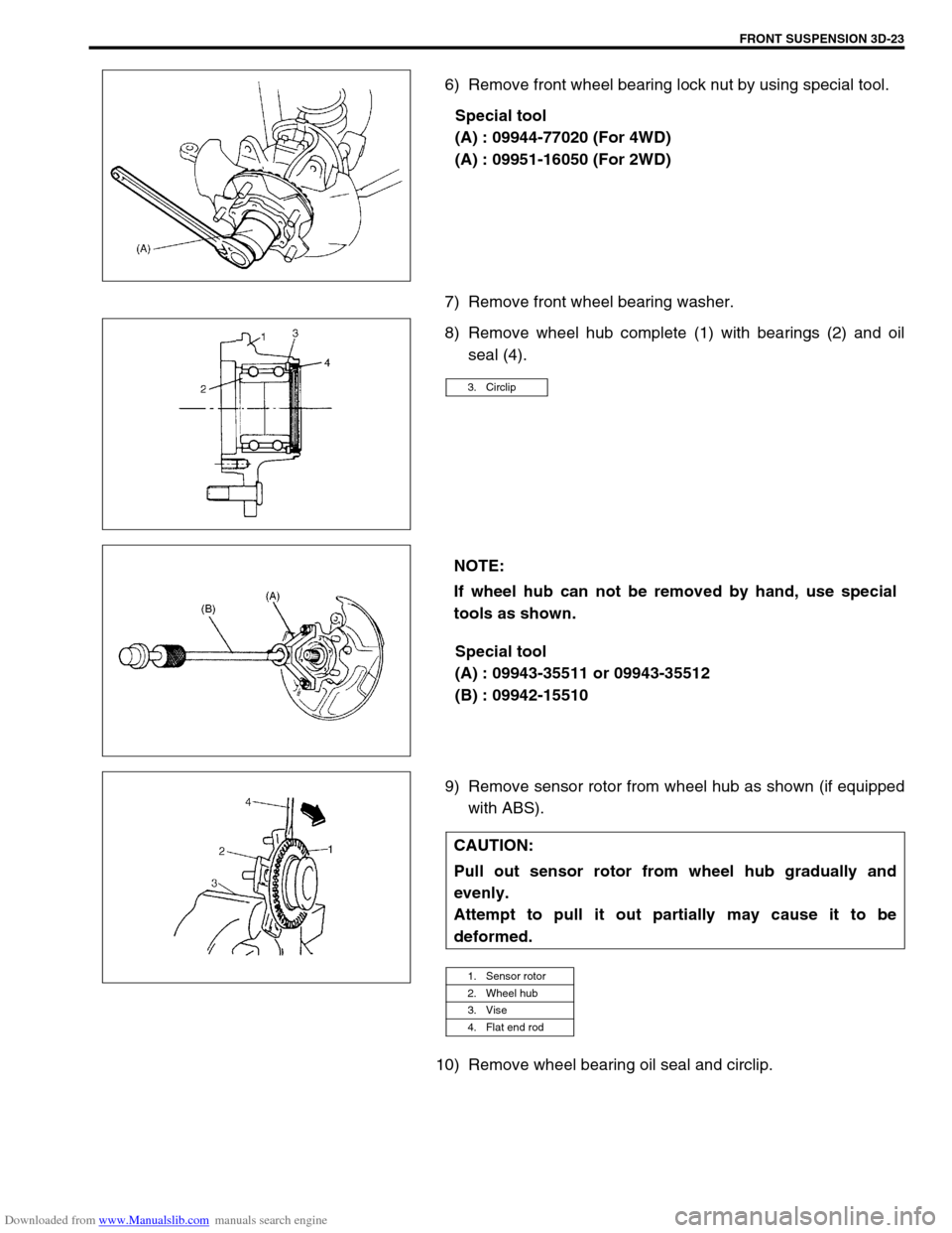
6) Remove front wheel bearing lock nut by using special tool.
Special tool
(A) : 09944-77020 (For 4WD)
(A) : 09951-16050 (For 2WD)
7) Remove front wheel bearing washer.
8) Remove wheel hub complete (1) with bearings (2) and oil
seal (4).
Special tool
(A) : 09943-35511 or 09943-35512
(B) : 09942-15510
9) Remove sensor rotor from wheel hub as shown (if equipped
with ABS).
10) Remove wheel bearing oil seal and circlip.
3. Circlip
NOTE:
If wheel hub can not be removed by hand, use special
tools as shown.
CAUTION:
Pull out sensor rotor from wheel hub gradually and
evenly.
Attempt to pull it out partially may cause it to be
deformed.
1. Sensor rotor
2. Wheel hub
3. Vise
4. Flat end rod
Page 198 of 687
Downloaded from www.Manualslib.com manuals search engine FRONT SUSPENSION 3D-25
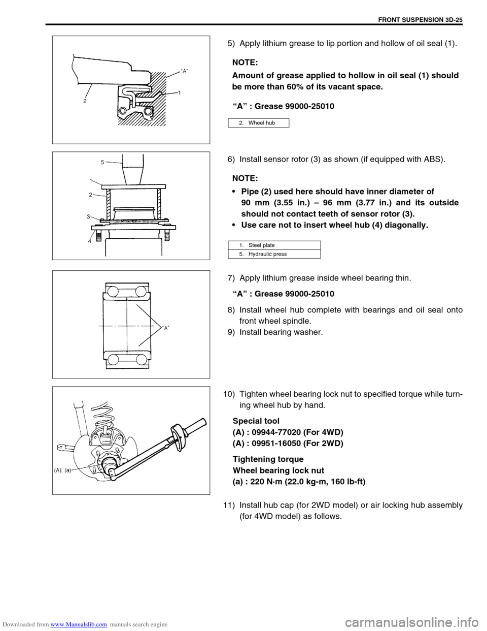
5) Apply lithium grease to lip portion and hollow of oil seal (1).
“A” : Grease 99000-25010
6) Install sensor rotor (3) as shown (if equipped with ABS).
7) Apply lithium grease inside wheel bearing thin.
“A” : Grease 99000-25010
8) Install wheel hub complete with bearings and oil seal onto
front wheel spindle.
9) Install bearing washer.
10) Tighten wheel bearing lock nut to specified torque while turn-
ing wheel hub by hand.
Special tool
(A) : 09944-77020 (For 4WD)
(A) : 09951-16050 (For 2WD)
Tightening torque
Wheel bearing lock nut
(a) : 220 N·m (22.0 kg-m, 160 lb-ft)
11) Install hub cap (for 2WD model) or air locking hub assembly
(for 4WD model) as follows. NOTE:
Amount of grease applied to hollow in oil seal (1) should
be more than 60% of its vacant space.
2. Wheel hub
NOTE:
Pipe (2) used here should have inner diameter of
90 mm (3.55 in.) – 96 mm (3.77 in.) and its outside
should not contact teeth of sensor rotor (3).
Use care not to insert wheel hub (4) diagonally.
1. Steel plate
5. Hydraulic press