differential SUZUKI JIMNY 2005 3.G Service User Guide
[x] Cancel search | Manufacturer: SUZUKI, Model Year: 2005, Model line: JIMNY, Model: SUZUKI JIMNY 2005 3.GPages: 687, PDF Size: 13.38 MB
Page 212 of 687
Downloaded from www.Manualslib.com manuals search engine FRONT SUSPENSION 3D-39
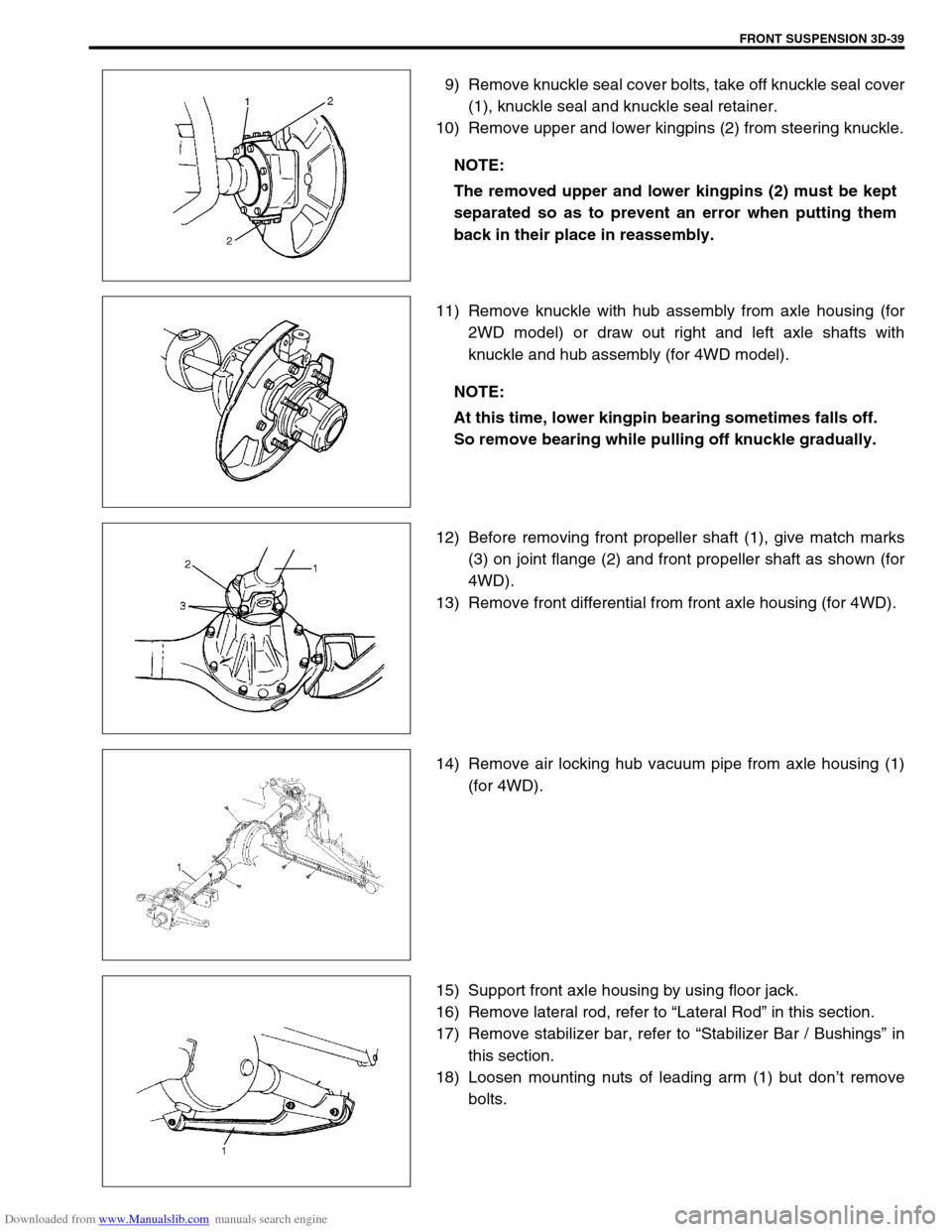
9) Remove knuckle seal cover bolts, take off knuckle seal cover
(1), knuckle seal and knuckle seal retainer.
10) Remove upper and lower kingpins (2) from steering knuckle.
11) Remove knuckle with hub assembly from axle housing (for
2WD model) or draw out right and left axle shafts with
knuckle and hub assembly (for 4WD model).
12) Before removing front propeller shaft (1), give match marks
(3) on joint flange (2) and front propeller shaft as shown (for
4WD).
13) Remove front differential from front axle housing (for 4WD).
14) Remove air locking hub vacuum pipe from axle housing (1)
(for 4WD).
15) Support front axle housing by using floor jack.
16) Remove lateral rod, refer to “Lateral Rod” in this section.
17) Remove stabilizer bar, refer to “Stabilizer Bar / Bushings” in
this section.
18) Loosen mounting nuts of leading arm (1) but don’t remove
bolts. NOTE:
The removed upper and lower kingpins (2) must be kept
separated so as to prevent an error when putting them
back in their place in reassembly.
NOTE:
At this time, lower kingpin bearing sometimes falls off.
So remove bearing while pulling off knuckle gradually.
Page 214 of 687
Downloaded from www.Manualslib.com manuals search engine FRONT SUSPENSION 3D-41
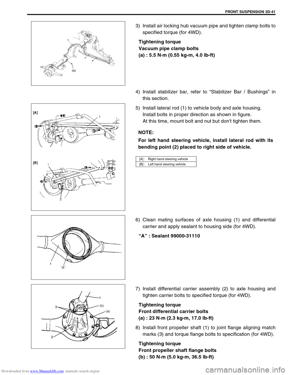
3) Install air locking hub vacuum pipe and tighten clamp bolts to
specified torque (for 4WD).
Tightening torque
Vacuum pipe clamp bolts
(a) : 5.5 N·m (0.55 kg-m, 4.0 lb-ft)
4) Install stabilizer bar, refer to “Stabilizer Bar / Bushings” in
this section.
5) Install lateral rod (1) to vehicle body and axle housing.
Install bolts in proper direction as shown in figure.
At this time, mount bolt and nut but don't tighten them.
6) Clean mating surfaces of axle housing (1) and differential
carrier and apply sealant to housing side (for 4WD).
“A” : Sealant 99000-31110
7) Install differential carrier assembly (2) to axle housing and
tighten carrier bolts to specified torque (for 4WD).
Tightening torque
Front differential carrier bolts
(a) : 23 N·m (2.3 kg-m, 17.0 lb-ft)
8) Install front propeller shaft (1) to joint flange aligning match
marks (3) and torque flange bolts to specification (for 4WD).
Tightening torque
Front propeller shaft flange bolts
(b) : 50 N·m (5.0 kg-m, 36.5 lb-ft)
NOTE:
For left hand steering vehicle, install lateral rod with its
bending point (2) placed to right side of vehicle.
[A] : Right hand steering vehicle
[B] : Left hand steering vehicle
Page 216 of 687

Downloaded from www.Manualslib.com manuals search engine FRONT SUSPENSION 3D-43
17) Tighten lateral rod (1) mounting bolt and nut to specified
torque.
Tightening torque
Lateral rod bolt and nut
(a) : 90 N·m (9.0 kg-m, 65.0 lb-ft)
18) Tighten right and left shock absorber lower mounting nuts
and leading arm mounting nuts to specified torque.
Tightening torque
Shock absorber lower nuts and leading arm nuts
(a) : 90 N·m (9.0 kg-m, 65.0 lb-ft)
19) Refill front axle (differential) housing with new specified gear
oil. Refer to “Maintenance Service” in Section 7E for refill.
20) Confirm front end (wheel) alignment referring to “Preliminary
Checks Prior to Adjusting Front Alignment” in Section 3A. NOTE:
When tightening bolt and nut, be sure that vehicle is off
hoist and in non loaded condition.
NOTE:
When tightening these nuts, be sure that vehicle is off
hoist and in non loaded condition.
1. Shock absorber
2. Leading arm
Page 217 of 687

Downloaded from www.Manualslib.com manuals search engine 3D-44 FRONT SUSPENSION
Tightening Torque Specifications
Required Service Material
Fastening partTightening torque
Nm kg-m lb-ft
Stabilizer mount bracket bolt 20 2.0 14.5
Stabilizer ball joint nut 50 5.0 36.5
Shock absorber lock nut 29 2.9 21.0
Shock absorber lower nut 90 9.0 65.0
Brake caliper carrier bolt 85 8.5 61.5
Wheel bearing lock nut 220 22.0 160.0
Wheel bearing lock washer screw 1.5 0.15 1.0
Air locking hub bolt 48 4.8 35.0
Wheel spindle bolt 50 5.0 36.5
Kingpin bolt 25 2.5 18.0
Knuckle seal cover bolt 10 1.0 7.5
Tie-rod end nut
43 4.3 31.5
Drag-rod end nut (Knuckle side)
Lateral rod bolt and nut
90 9.0 65.0
Leading arm nut
Front differential carrier bolt 23 2.3 17.0
Front propeller shaft flange bolt 50 5.0 36.5
Wheel nut 95 9.5 69.0
Vacuum pipe clamp bolt 5.5 0.55 4.0
MaterialRecommended SUZUKI product
(Part Number)Use
Lithium grease SUZUKI SUPER GREASE (A)
(99000-25010)Knuckle seal / axle shaft oil seal
Recess of wheel spindles
Wheel hub oil seal
Wheel bearing
Spindle thrust washer
Spindle bush (inside and flange
part)
Spindle oil seal
SUZUKI SUPER GREASE (C)
(99000-25030)Kingpin bearing
Axle shaft joint (for 4WD)
Sealant SUZUKI BOND NO. 1215
(99000-31110)Mating surfaces of wheel spindle
and knuckle
Mating surface of differential carrier
and axle housing
Sealing compound SUZUKI SEALING COMPOUND
366E
(99000-31090)Mating surface of wheel spindle and
knuckle
Kingpin
Mating surfaces of hub cap and
wheel hub
Page 235 of 687
Downloaded from www.Manualslib.com manuals search engine 3E-16 REAR SUSPENSION
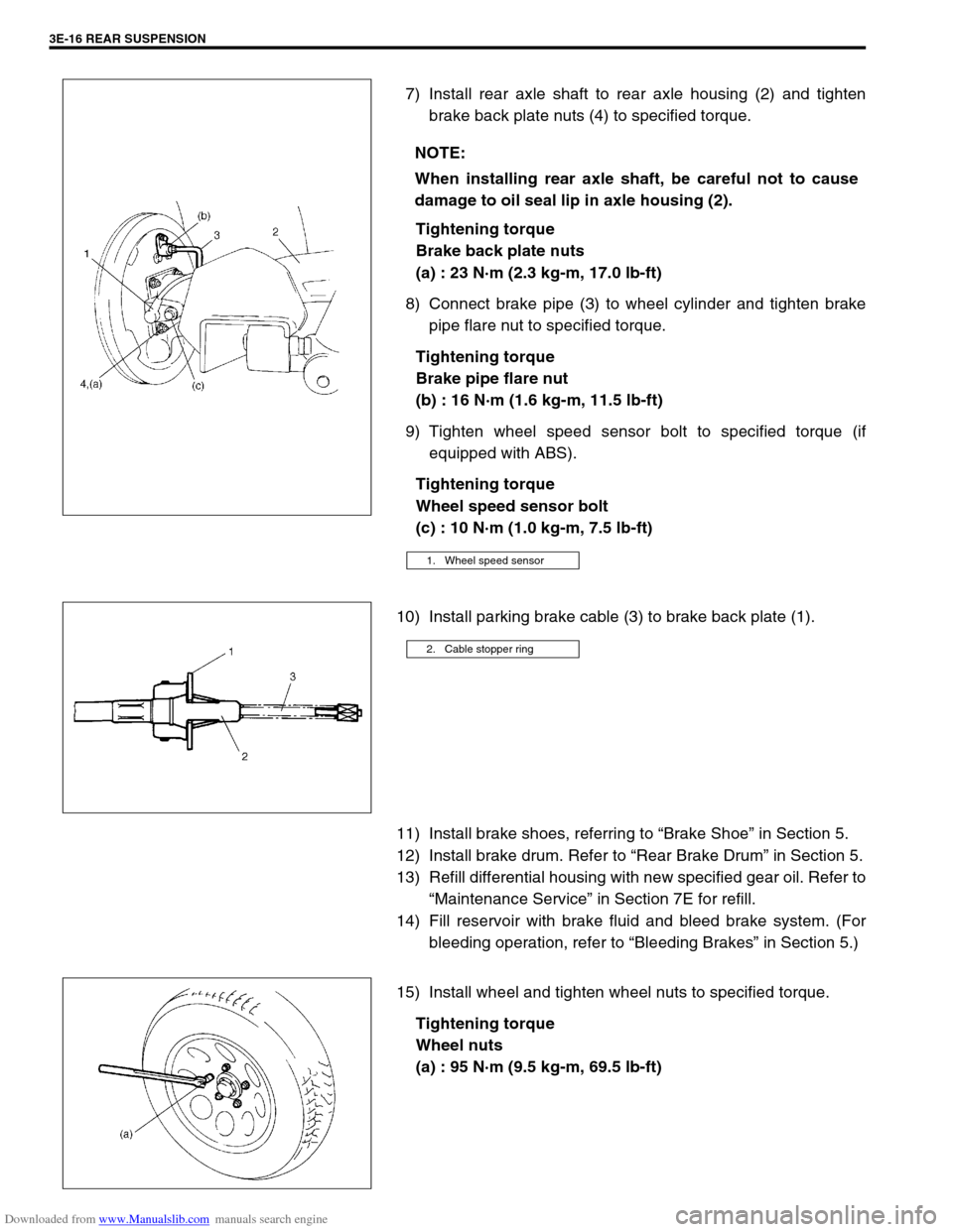
7) Install rear axle shaft to rear axle housing (2) and tighten
brake back plate nuts (4) to specified torque.
Tightening torque
Brake back plate nuts
(a) : 23 N·m (2.3 kg-m, 17.0 lb-ft)
8) Connect brake pipe (3) to wheel cylinder and tighten brake
pipe flare nut to specified torque.
Tightening torque
Brake pipe flare nut
(b) : 16 N·m (1.6 kg-m, 11.5 lb-ft)
9) Tighten wheel speed sensor bolt to specified torque (if
equipped with ABS).
Tightening torque
Wheel speed sensor bolt
(c) : 10 N·m (1.0 kg-m, 7.5 lb-ft)
10) Install parking brake cable (3) to brake back plate (1).
11) Install brake shoes, referring to “Brake Shoe” in Section 5.
12) Install brake drum. Refer to “Rear Brake Drum” in Section 5.
13) Refill differential housing with new specified gear oil. Refer to
“Maintenance Service” in Section 7E for refill.
14) Fill reservoir with brake fluid and bleed brake system. (For
bleeding operation, refer to “Bleeding Brakes” in Section 5.)
15) Install wheel and tighten wheel nuts to specified torque.
Tightening torque
Wheel nuts
(a) : 95 N·m (9.5 kg-m, 69.5 lb-ft) NOTE:
When installing rear axle shaft, be careful not to cause
damage to oil seal lip in axle housing (2).
1. Wheel speed sensor
2. Cable stopper ring
Page 236 of 687
Downloaded from www.Manualslib.com manuals search engine REAR SUSPENSION 3E-17
16) Upon completion of all jobs, depress brake pedal with about
30 kg (66 lbs) load over ten times so as to obtain proper
drum-to shoe clearance.
Adjust parking brake cable. (For adjustment, refer to “Parking
Brake Check and Adjustment” in Section 5.)
17) Tighten parking brake lever cover screws.
18) Check to ensure that brake drum is free from dragging and
proper braking is obtained. Then remove vehicle from hoist
and perform brake test (foot brake and parking brake).
19) Check each installed part for oil leakage.
Rear Axle Shaft Inner Oil Seal
REMOVAL
1) Remove rear axle shaft. For details, refer to “Rear Axle Shaft
and Wheel Bearing” in this section.
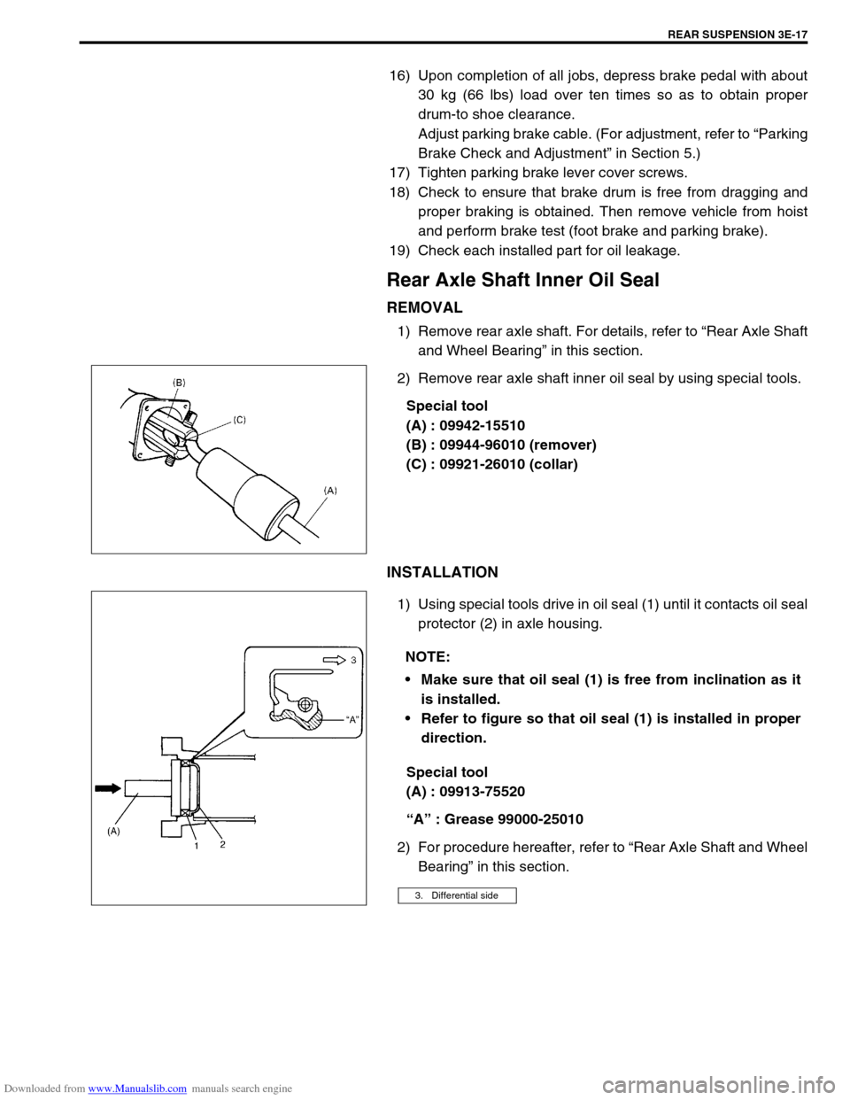
2) Remove rear axle shaft inner oil seal by using special tools.
Special tool
(A) : 09942-15510
(B) : 09944-96010 (remover)
(C) : 09921-26010 (collar)
INSTALLATION
1) Using special tools drive in oil seal (1) until it contacts oil seal
protector (2) in axle housing.
Special tool
(A) : 09913-75520
“A” : Grease 99000-25010
2) For procedure hereafter, refer to “Rear Axle Shaft and Wheel
Bearing” in this section.
NOTE:
Make sure that oil seal (1) is free from inclination as it
is installed.
Refer to figure so that oil seal (1) is installed in proper
direction.
3. Differential side
Page 237 of 687
Downloaded from www.Manualslib.com manuals search engine 3E-18 REAR SUSPENSION
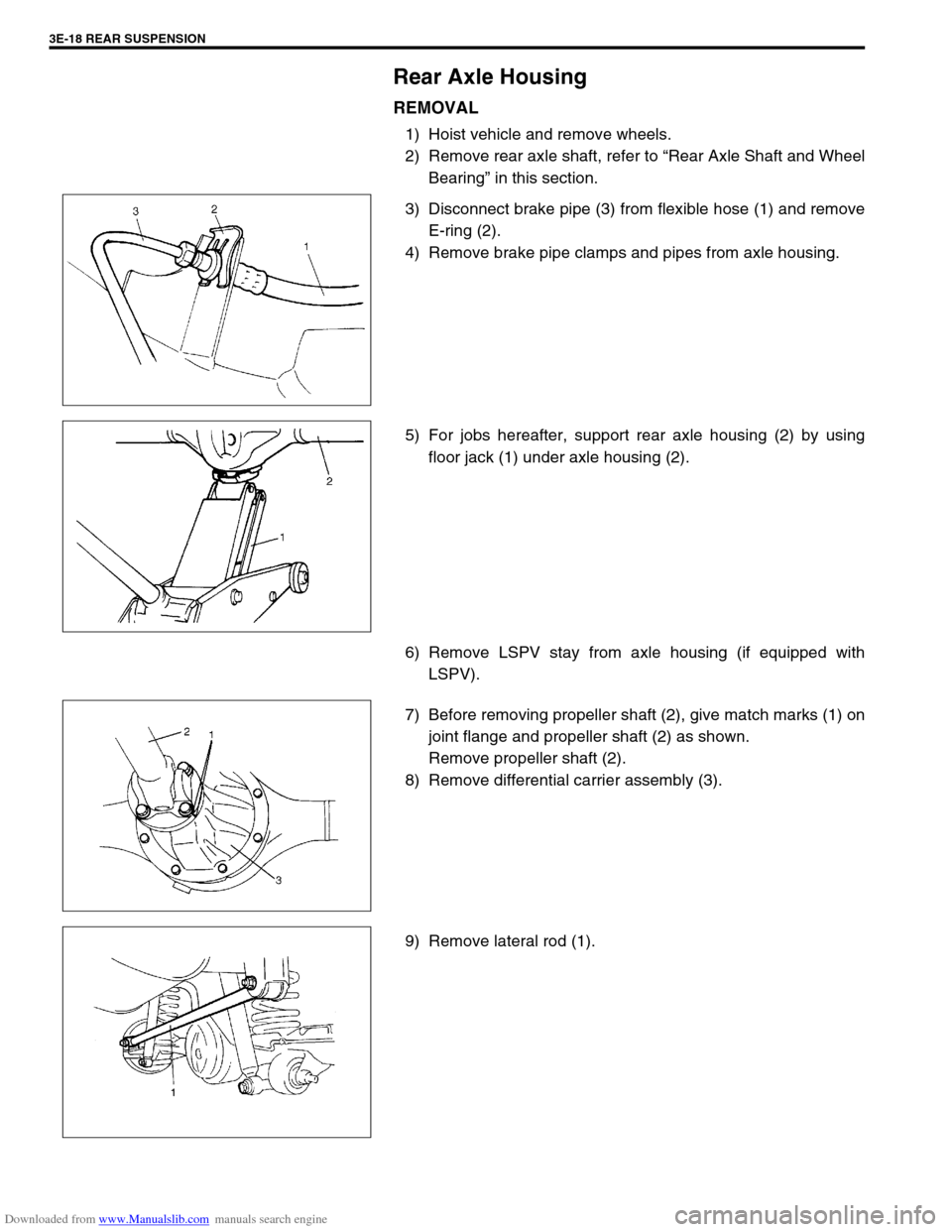
Rear Axle Housing
REMOVAL
1) Hoist vehicle and remove wheels.
2) Remove rear axle shaft, refer to “Rear Axle Shaft and Wheel
Bearing” in this section.
3) Disconnect brake pipe (3) from flexible hose (1) and remove
E-ring (2).
4) Remove brake pipe clamps and pipes from axle housing.
5) For jobs hereafter, support rear axle housing (2) by using
floor jack (1) under axle housing (2).
6) Remove LSPV stay from axle housing (if equipped with
LSPV).
7) Before removing propeller shaft (2), give match marks (1) on
joint flange and propeller shaft (2) as shown.
Remove propeller shaft (2).
8) Remove differential carrier assembly (3).
9) Remove lateral rod (1).
Page 239 of 687
Downloaded from www.Manualslib.com manuals search engine 3E-20 REAR SUSPENSION
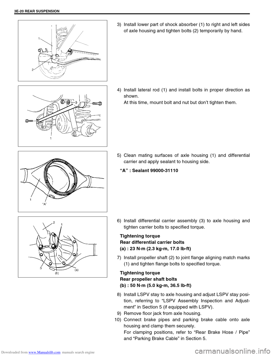
3) Install lower part of shock absorber (1) to right and left sides
of axle housing and tighten bolts (2) temporarily by hand.
4) Install lateral rod (1) and install bolts in proper direction as
shown.
At this time, mount bolt and nut but don’t tighten them.
5) Clean mating surfaces of axle housing (1) and differential
carrier and apply sealant to housing side.
“A” : Sealant 99000-31110
6) Install differential carrier assembly (3) to axle housing and
tighten carrier bolts to specified torque.
Tightening torque
Rear differential carrier bolts
(a) : 23 N·m (2.3 kg-m, 17.0 lb-ft)
7) Install propeller shaft (2) to joint flange aligning match marks
(1) and tighten flange bolts to specified torque.
Tightening torque
Rear propeller shaft bolts
(b) : 50 N·m (5.0 kg-m, 36.5 lb-ft)
8) Install LSPV stay to axle housing and adjust LSPV stay posi-
tion, referring to “LSPV Assembly Inspection and Adjust-
ment” in Section 5 (if equipped with LSPV).
9) Remove floor jack from axle housing.
10) Connect brake pipes and parking brake cable onto axle
housing and clamp them securely.
For clamping positions, refer to “Rear Brake Hose / Pipe”
and “Parking Brake Cable” in Section 5.
Page 241 of 687

Downloaded from www.Manualslib.com manuals search engine 3E-22 REAR SUSPENSION
Tightening Torque Specifications
Required Service Materials
Fastening portionTightening torque
Nm kg-m lb-ft
Shock absorber upper and lower bolt 85 8.5 61.5
Bump stopper 50 5.0 36.5
Lateral rod bolt and nut
90 9.0 65.0
Trailing arm nut (Front and Rear)
Brake back plate nut 23 2.3 17.0
Brake pipe flare nut 16 1.6 11.5
Rear differential carrier bolt 23 2.3 17.0
Rear propeller shaft bolt (Differential case side) 50 5.0 36.5
Rear propeller shaft bolt (Shaft No.3 transfer case side) 33 3.3 24.0
Wheel nut 95 9.5 69.0
Wheel speed sensor bolt and harness clamp bolt 10 1.0 7.5
MaterialRecommended SUZUKI product
(Part Number)Use
Lithium greaseSUZUKI SUPER GREASE A
(99000-25010)Oil seal lip
SealantSUZUKI BOND NO. 1215
(99000-31110)Joint seam of differential carrier and
axle housing
Water tight sealantSEALING COMPOUND 366E
(99000-31090)To apply to mating surfaces of brake
back plate and rear axle.
Gear oilFor gear oil information, refer to “Mainte-
nance Service” in Section 7E of this manual.Differential gear
(Rear axle housing)
Page 248 of 687

Downloaded from www.Manualslib.com manuals search engine WHEELS AND TIRES 3F-5
WARNING:
Wheel spin should be limited to 35 mph (55 km/h) as indicated on speedometer.
This limit is necessary because speedometer only indicates one-half of actual wheel speed when one
drive wheel is spinning and the other drive wheel is stopped.
Unless care is taken in limiting drive wheel spin, spinning wheel can reach excessive speeds. This
can result in possible tire disintegration or differential failure, which could cause serious personal
injury or extensive vehicle damage.
CAUTION:
For vehicle equipped with ABS, using on-vehicle balancing method with ignition switch ON may set
malfunction diagnostic trouble code (DTC) of ABS even when system is in good condition.
Never turn ignition switch ON while spinning wheel.