lights SUZUKI JIMNY 2005 3.G Service User Guide
[x] Cancel search | Manufacturer: SUZUKI, Model Year: 2005, Model line: JIMNY, Model: SUZUKI JIMNY 2005 3.GPages: 687, PDF Size: 13.38 MB
Page 620 of 687

Downloaded from www.Manualslib.com manuals search engine ENGINE AND EMISSION CONTROL SYSTEM 6E-15
On-Vehicle Service
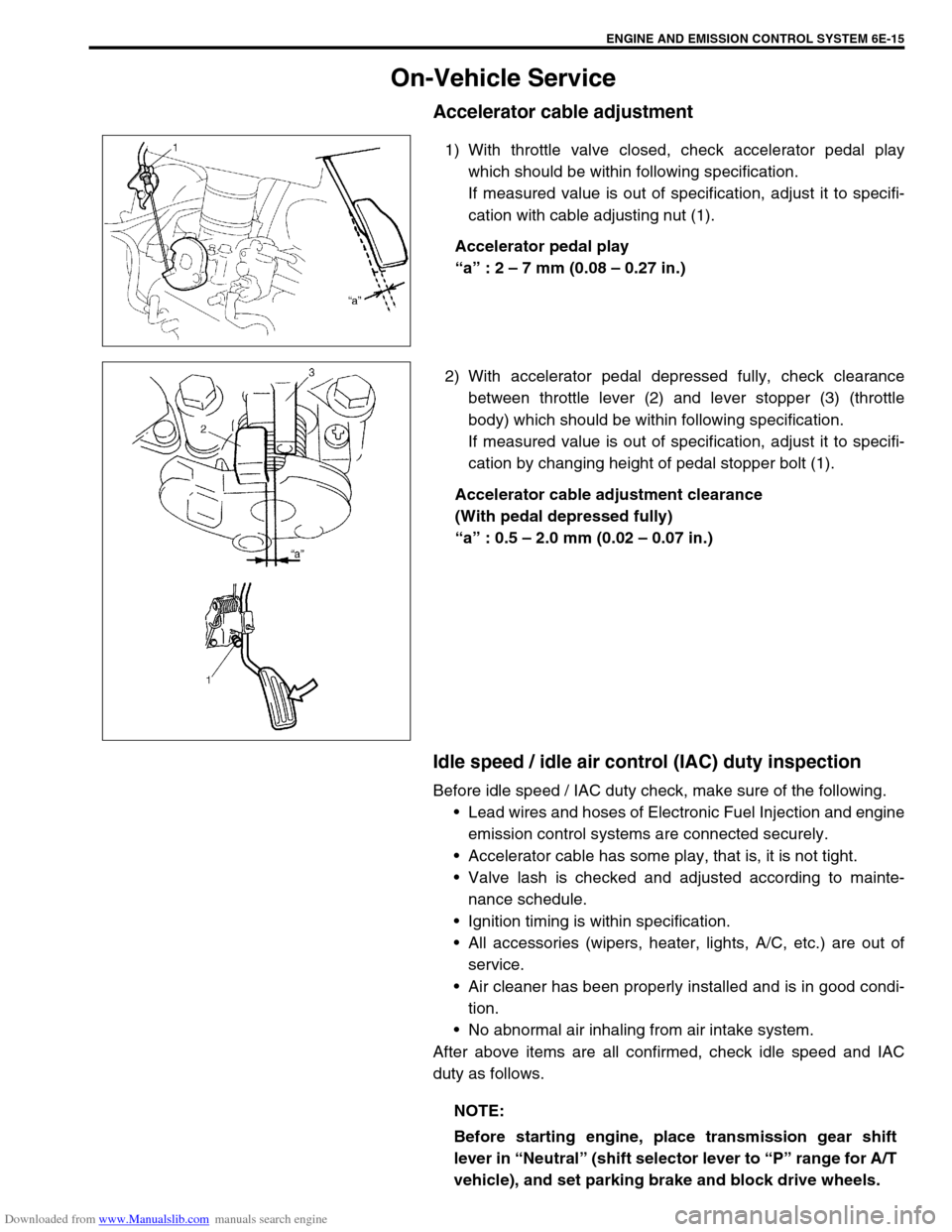
Accelerator cable adjustment
1) With throttle valve closed, check accelerator pedal play
which should be within following specification.
If measured value is out of specification, adjust it to specifi-
cation with cable adjusting nut (1).
Accelerator pedal play
“a” : 2 – 7 mm (0.08 – 0.27 in.)
2) With accelerator pedal depressed fully, check clearance
between throttle lever (2) and lever stopper (3) (throttle
body) which should be within following specification.
If measured value is out of specification, adjust it to specifi-
cation by changing height of pedal stopper bolt (1).
Accelerator cable adjustment clearance
(With pedal depressed fully)
“a” : 0.5 – 2.0 mm (0.02 – 0.07 in.)
Idle speed / idle air control (IAC) duty inspection
Before idle speed / IAC duty check, make sure of the following.
Lead wires and hoses of Electronic Fuel Injection and engine
emission control systems are connected securely.
Accelerator cable has some play, that is, it is not tight.
Valve lash is checked and adjusted according to mainte-
nance schedule.
Ignition timing is within specification.
All accessories (wipers, heater, lights, A/C, etc.) are out of
service.
Air cleaner has been properly installed and is in good condi-
tion.
No abnormal air inhaling from air intake system.
After above items are all confirmed, check idle speed and IAC
duty as follows.
NOTE:
Before starting engine, place transmission gear shift
lever in “Neutral” (shift selector lever to “P” range for A/T
vehicle), and set parking brake and block drive wheels.
Page 677 of 687

Downloaded from www.Manualslib.com manuals search engine 6H-10 CHARGING SYSTEM
1) Set parking brake and place automatic transmission in
PARK (NEUTRAL on manual transmission). Turn off ignition,
turn off lights and all other electrical loads.
2) Check electrolyte level. If it is below low level line, add dis-
tilled water.
3) Attach end of one jumper cable to positive terminal of
booster battery and the other end of the same cable to posi-
tive terminal of discharged battery. (Use 12-volt battery only
to jump start engine).
4) Attach one end of the remaining negative cable to negative
terminal of booster battery, and the other end to a solid
engine ground (such as exhaust manifold) at least 45 cm (18
in.) away from battery of vehicle being started.
5) Start engine of vehicle with booster battery and turn off elec-
trical accessories. Then start engine of the vehicle with dis-
charged battery.
6) Disconnect jumper cables in the exact reverse order.
WITH CHARGING EQUIPMENT
WARNING:
Departure from these conditions or procedure
described below could result in:
–Serious personal injury (particularly to eyes) or
property damage from such causes as battery explo-
sion, battery acid, or electrical burns.
–Damage to electronic components of either vehicle.
Remove rings, watches, and other jewelry. Wear
approved eye protection.
Be careful so that metal tools or jumper cables do not
contact positive battery terminal (or metal in contact
with it) and any other metal on vehicle, because a short
circuit could occur.
WARNING:
Do not connect negative cable directly to negative termi-
nal of dead battery.
CAUTION:
When jump starting engine with charging equipment, be
sure equipment used is 12-volt and negative ground. Do
not use 24-volt charging equipment. Using such equip-
ment can cause serious damage to electrical system or
electronic parts.