lock SUZUKI JIMNY 2005 3.G Service User Guide
[x] Cancel search | Manufacturer: SUZUKI, Model Year: 2005, Model line: JIMNY, Model: SUZUKI JIMNY 2005 3.GPages: 687, PDF Size: 13.38 MB
Page 28 of 687
Downloaded from www.Manualslib.com manuals search engine GENERAL INFORMATION 0A-23
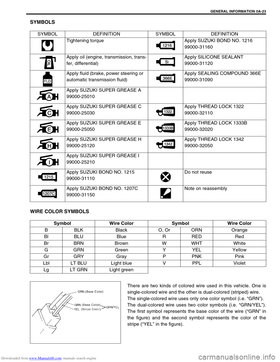
SYMBOLS
WIRE COLOR SYMBOLS
There are two kinds of colored wire used in this vehicle. One is
single-colored wire and the other is dual-colored (striped) wire.
The single-colored wire uses only one color symbol (i.e. “GRN”).
The dual-colored wire uses two color symbols (i.e. “GRN/YEL”).
The first symbol represents the base color of the wire (“GRN” in
the figure) and the second symbol represents the color of the
stripe (“YEL” in the figure). SYMBOL DEFINITION SYMBOL DEFINITION
Tightening torque Apply SUZUKI BOND NO. 1216
99000-31160
Apply oil (engine, transmission, trans-
fer, differential)Apply SILICONE SEALANT
99000-31120
Apply fluid (brake, power steering or
automatic transmission fluid)Apply SEALING COMPOUND 366E
99000-31090
Apply SUZUKI SUPER GREASE A
99000-25010
Apply SUZUKI SUPER GREASE C
99000-25030Apply THREAD LOCK 1322
99000-32110
Apply SUZUKI SUPER GREASE E
99000-25050Apply THREAD LOCK 1333B
99000-32020
Apply SUZUKI SUPER GREASE H
99000-25120Apply THREAD LOCK 1342
99000-32050
Apply SUZUKI SUPER GREASE I
99000-25210
Apply SUZUKI BOND NO. 1215
99000-31110Do not reuse
Apply SUZUKI BOND NO. 1207C
99000-31150Note on reassembly
Symbol Wire Color Symbol Wire Color
B BLK Black O, Or ORN Orange
Bl BLU Blue R RED Red
Br BRN Brown W WHT White
GGRN Green Y YEL Yellow
Gr GRY Gray P PNK Pink
Lbl LT BLU Light blue V PPL Violet
Lg LT GRN Light green
Page 29 of 687
Downloaded from www.Manualslib.com manuals search engine 0A-24 GENERAL INFORMATION
Fasteners Information
Metric Fasteners
Most of the fasteners used for this vehicle are metric fasteners. When replacing any fasteners, it is most impor-
tant that replacement fasteners be the correct diameter, thread pitch and strength.
Fastener Strength Identification
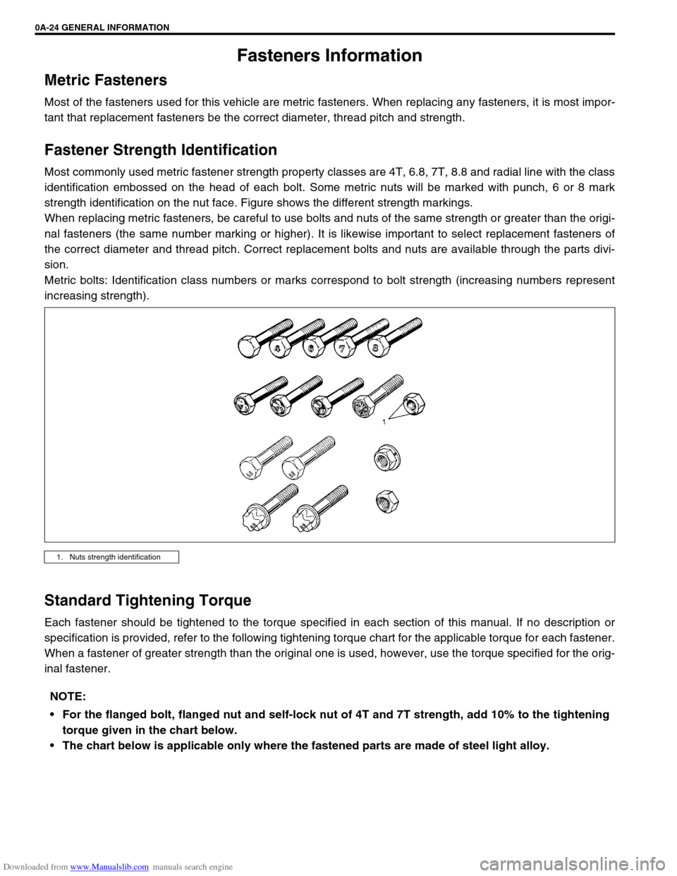
Most commonly used metric fastener strength property classes are 4T, 6.8, 7T, 8.8 and radial line with the class
identification embossed on the head of each bolt. Some metric nuts will be marked with punch, 6 or 8 mark
strength identification on the nut face. Figure shows the different strength markings.
When replacing metric fasteners, be careful to use bolts and nuts of the same strength or greater than the origi-
nal fasteners (the same number marking or higher). It is likewise important to select replacement fasteners of
the correct diameter and thread pitch. Correct replacement bolts and nuts are available through the parts divi-
sion.
Metric bolts: Identification class numbers or marks correspond to bolt strength (increasing numbers represent
increasing strength).
Standard Tightening Torque
Each fastener should be tightened to the torque specified in each section of this manual. If no description or
specification is provided, refer to the following tightening torque chart for the applicable torque for each fastener.
When a fastener of greater strength than the original one is used, however, use the torque specified for the orig-
inal fastener.
1. Nuts strength identification
NOTE:
For the flanged bolt, flanged nut and self-lock nut of 4T and 7T strength, add 10% to the tightening
torque given in the chart below.
The chart below is applicable only where the fastened parts are made of steel light alloy.
Page 30 of 687
Downloaded from www.Manualslib.com manuals search engine GENERAL INFORMATION 0A-25
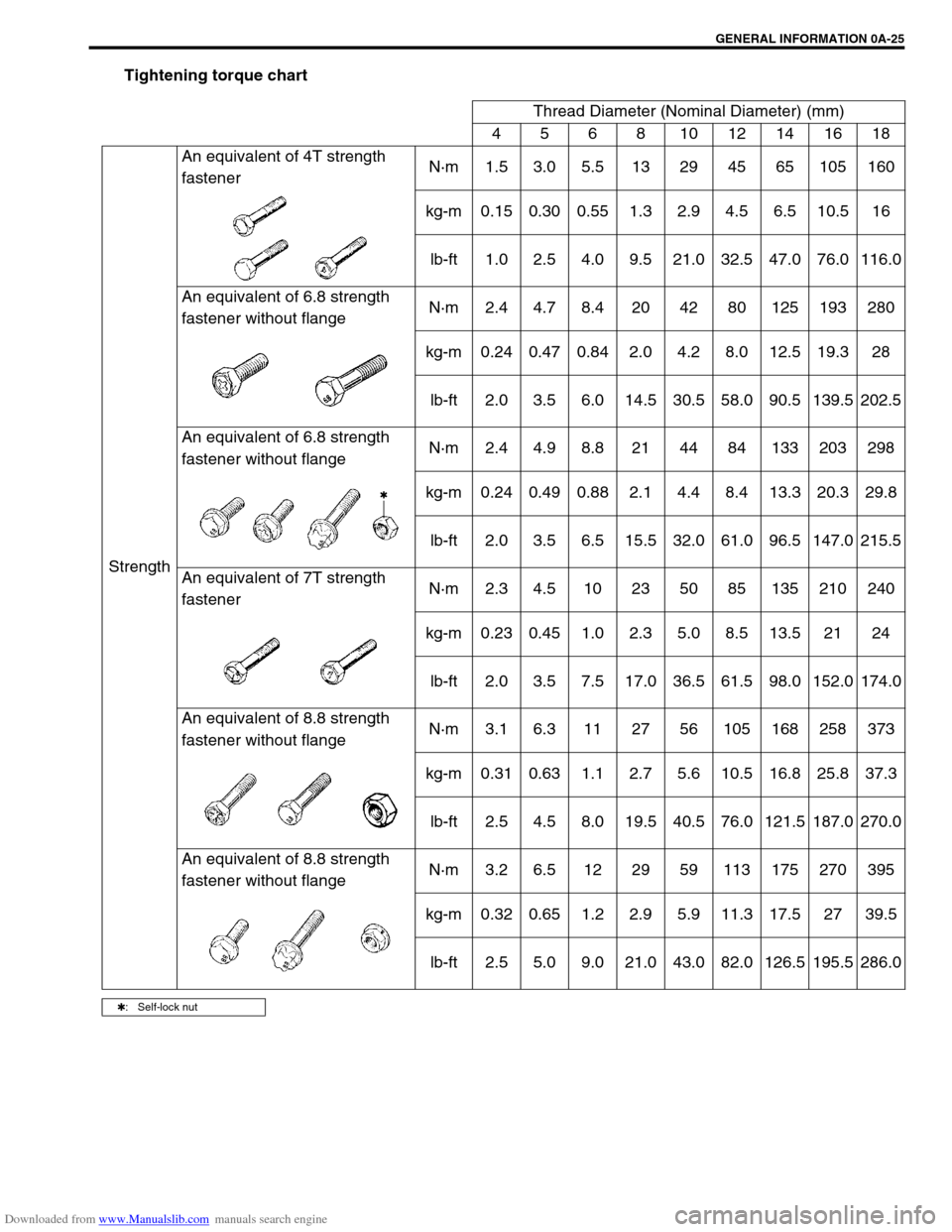
Tightening torque chart
Thread Diameter (Nominal Diameter) (mm)
4 5 6 8 10 12 14 16 18
StrengthAn equivalent of 4T strength
fastenerN·m 1.5 3.0 5.5 13 29 45 65 105 160
kg-m 0.15 0.30 0.55 1.3 2.9 4.5 6.5 10.5 16
lb-ft 1.0 2.5 4.0 9.5 21.0 32.5 47.0 76.0 116.0
An equivalent of 6.8 strength
fastener without flangeN·m 2.4 4.7 8.4 20 42 80 125 193 280
kg-m 0.24 0.47 0.84 2.0 4.2 8.0 12.5 19.3 28
lb-ft 2.0 3.5 6.0 14.5 30.5 58.0 90.5 139.5 202.5
An equivalent of 6.8 strength
fastener without flangeN·m 2.4 4.9 8.8 21 44 84 133 203 298
kg-m 0.24 0.49 0.88 2.1 4.4 8.4 13.3 20.3 29.8
lb-ft 2.0 3.5 6.5 15.5 32.0 61.0 96.5 147.0 215.5
An equivalent of 7T strength
fastenerN·m 2.3 4.5 10 23 50 85 135 210 240
kg-m 0.23 0.45 1.0 2.3 5.0 8.5 13.5 21 24
lb-ft 2.0 3.5 7.5 17.0 36.5 61.5 98.0 152.0 174.0
An equivalent of 8.8 strength
fastener without flangeN·m 3.1 6.3 11 27 56 105 168 258 373
kg-m 0.31 0.63 1.1 2.7 5.6 10.5 16.8 25.8 37.3
lb-ft 2.5 4.5 8.0 19.5 40.5 76.0 121.5 187.0 270.0
An equivalent of 8.8 strength
fastener without flangeN·m 3.2 6.5 12 29 59 113 175 270 395
kg-m 0.32 0.65 1.2 2.9 5.9 11.3 17.5 27 39.5
lb-ft 2.5 5.0 9.0 21.0 43.0 82.0 126.5 195.5 286.0
✱: Self-lock nut
Page 32 of 687
Downloaded from www.Manualslib.com manuals search engine MAINTENANCE AND LUBRICATION 0B-1
0A 6F1
0B
0B
6G
1A 6H
1B 6K
37A
3A 7A1
3B1 7B1
3C1 7C1
3D 7D
3E 7E
3F 7F
4A2 8A
4B 8B
8C
58D
5A 8E
5B
5C 9
5E
5E1 10
10A
610B
6-1
6A1
6A2
6A4
6B
6C
6E1
6E2
SECTION 0B
MAINTENANCE AND LUBRICATION
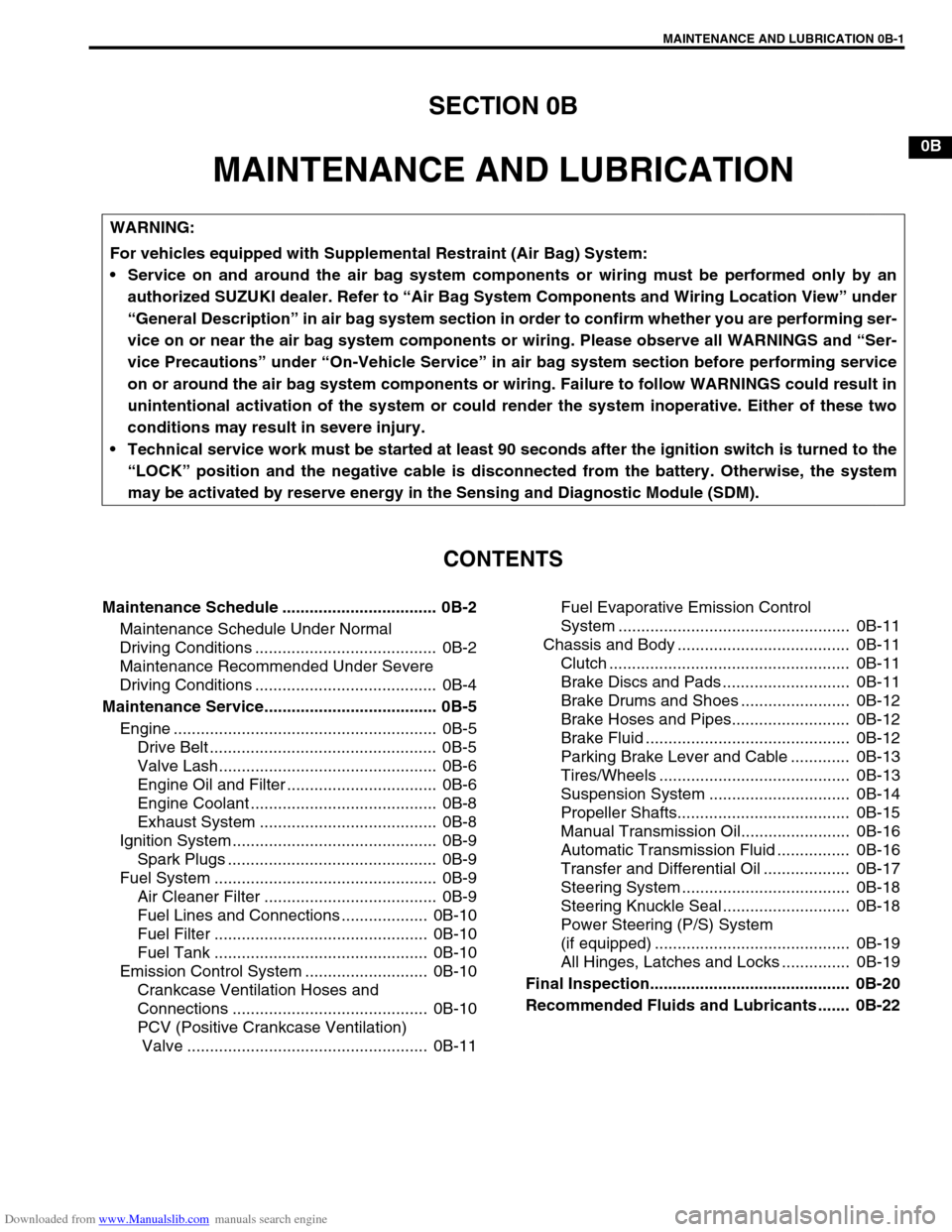
CONTENTS
Maintenance Schedule .................................. 0B-2
Maintenance Schedule Under Normal
Driving Conditions ........................................ 0B-2
Maintenance Recommended Under Severe
Driving Conditions ........................................ 0B-4
Maintenance Service...................................... 0B-5
Engine .......................................................... 0B-5
Drive Belt .................................................. 0B-5
Valve Lash................................................ 0B-6
Engine Oil and Filter ................................. 0B-6
Engine Coolant ......................................... 0B-8
Exhaust System ....................................... 0B-8
Ignition System ............................................. 0B-9
Spark Plugs .............................................. 0B-9
Fuel System ................................................. 0B-9
Air Cleaner Filter ...................................... 0B-9
Fuel Lines and Connections ................... 0B-10
Fuel Filter ............................................... 0B-10
Fuel Tank ............................................... 0B-10
Emission Control System ........................... 0B-10
Crankcase Ventilation Hoses and
Connections ........................................... 0B-10
PCV (Positive Crankcase Ventilation)
Valve ..................................................... 0B-11Fuel Evaporative Emission Control
System ................................................... 0B-11
Chassis and Body ...................................... 0B-11
Clutch ..................................................... 0B-11
Brake Discs and Pads ............................ 0B-11
Brake Drums and Shoes ........................ 0B-12
Brake Hoses and Pipes.......................... 0B-12
Brake Fluid ............................................. 0B-12
Parking Brake Lever and Cable ............. 0B-13
Tires/Wheels .......................................... 0B-13
Suspension System ............................... 0B-14
Propeller Shafts...................................... 0B-15
Manual Transmission Oil........................ 0B-16
Automatic Transmission Fluid ................ 0B-16
Transfer and Differential Oil ................... 0B-17
Steering System ..................................... 0B-18
Steering Knuckle Seal ............................ 0B-18
Power Steering (P/S) System
(if equipped) ........................................... 0B-19
All Hinges, Latches and Locks ............... 0B-19
Final Inspection............................................ 0B-20
Recommended Fluids and Lubricants ....... 0B-22
WARNING:
For vehicles equipped with Supplemental Restraint (Air Bag) System:
Service on and around the air bag system components or wiring must be performed only by an
authorized SUZUKI dealer. Refer to “Air Bag System Components and Wiring Location View” under
“General Description” in air bag system section in order to confirm whether you are performing ser-
vice on or near the air bag system components or wiring. Please observe all WARNINGS and “Ser-
vice Precautions” under “On-Vehicle Service” in air bag system section before performing service
on or around the air bag system components or wiring. Failure to follow WARNINGS could result in
unintentional activation of the system or could render the system inoperative. Either of these two
conditions may result in severe injury.
Technical service work must be started at least 90 seconds after the ignition switch is turned to the
“LOCK” position and the negative cable is disconnected from the battery. Otherwise, the system
may be activated by reserve energy in the Sensing and Diagnostic Module (SDM).
Page 34 of 687

Downloaded from www.Manualslib.com manuals search engine MAINTENANCE AND LUBRICATION 0B-3
IntervalKm (x 1,000) 153045607590
Miles (x 1,000) 9 18 27 36 45 54
Months 12 24 36 48 60 72
CHASSIS AND BODY
Clutch (pedal height and travel)–I–I–I
Brake discs and pads (thickness, wear, damage) I I I I I I
Brake drums and shoes (wear, damage)–I–I–I
Brake hoses and pipes (leakage, damage, clamp)–I–I–I
Brake fluid–R–R–R
Brake lever and cable (damage, stroke, operation) Inspect at first 15,000 km (9,000 miles) only.
Tires (wear, damage, rotation) I I I I I I
Wheel discs (damage) I I I I I I
Suspension system (tightness, damage, rattle, breakage)–I–I–I
Propeller shafts––I––I
Manual transmission oil (leakage, level) (I: 1st 15,000 km only) I–R––R
Automatic transmission Fluid level–I–I–I
Fluid change Replace every 165,000 km (99,000 miles).
Fluid hose–––R––
Transfer oil (leakage, level) I–I–I–
Differential oil (leakage, level) (R: 1st 15,000 km only) R or I–I–I–
Steering system (tightness, damage, breakage, rattle)–I–I–I
Power steering (if equipped) I I I I I I
All latches, hinges and locks–I–I–I
NOTE:
“R”: Replace or change
“I”: Inspect and correct, replace or lubricate if necessary
Page 50 of 687
Downloaded from www.Manualslib.com manuals search engine MAINTENANCE AND LUBRICATION 0B-19
Power Steering (P/S) System (if equipped)
INSPECTION
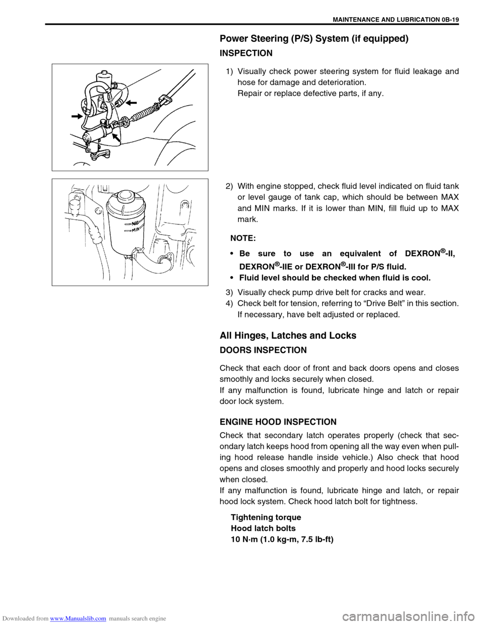
1) Visually check power steering system for fluid leakage and
hose for damage and deterioration.
Repair or replace defective parts, if any.
2) With engine stopped, check fluid level indicated on fluid tank
or level gauge of tank cap, which should be between MAX
and MIN marks. If it is lower than MIN, fill fluid up to MAX
mark.
3) Visually check pump drive belt for cracks and wear.
4) Check belt for tension, referring to “Drive Belt” in this section.
If necessary, have belt adjusted or replaced.
All Hinges, Latches and Locks
DOORS INSPECTION
Check that each door of front and back doors opens and closes
smoothly and locks securely when closed.
If any malfunction is found, lubricate hinge and latch or repair
door lock system.
ENGINE HOOD INSPECTION
Check that secondary latch operates properly (check that sec-
ondary latch keeps hood from opening all the way even when pull-
ing hood release handle inside vehicle.) Also check that hood
opens and closes smoothly and properly and hood locks securely
when closed.
If any malfunction is found, lubricate hinge and latch, or repair
hood lock system. Check hood latch bolt for tightness.
Tightening torque
Hood latch bolts
10 N·m (1.0 kg-m, 7.5 lb-ft)
NOTE:
Be sure to use an equivalent of DEXRON
®-II,
DEXRON
®-IIE or DEXRON®-III for P/S fluid.
Fluid level should be checked when fluid is cool.
Page 51 of 687

Downloaded from www.Manualslib.com manuals search engine 0B-20 MAINTENANCE AND LUBRICATION
Final Inspection
SEATS
Check that seat slides smoothly and locks securely at any position. Also check that reclining mechanism of front
seat back allows it to be locked at any angle.
SEAT BELT
Inspect belt system including webbing, buckles, latch plates, retractors and anchors for damage or wear.
If “REPLACE BELT” label on front seat belt is visible, replace belt. Check that seat belt is securely locked.
BATTERY ELECTROLYTE LEVEL CHECK
Check that the electrolyte level of all battery cells is between the upper and lower level lines on the case. If bat-
tery is equipped with built-in indicator, check battery condition by the indicator.
ACCELERATOR PEDAL OPERATION
Check that pedal operates smoothly without getting caught or interfered by any other part.
ENGINE START
Check engine start for readiness.
On automatic transmission vehicles, try to start the engine in each select lever position. The starting motor
should crank only in “P” (Park) or “N” (Neutral).
On manual transmission vehicles, place the shift lever in “Neutral,” depress clutch pedal fully any try to start.
EXHAUST SYSTEM CHECK
Check for leakage, cracks or loose supports.
CLUTCH (FOR MANUAL TRANSMISSION)
Check for the following.
Clutch is completely released when depressing clutch pedal,
No slipping clutch occurs when releasing pedal and accelerating.
Clutch itself is free from any abnormal condition. WARNING:
When carrying out road tests, select a safe place where no man or no running vehicle is seen so as to
prevent any accident.
WARNING:
Before performing the following check, be sure to have enough room around the vehicle. Then, firmly
apply both the parking brake and the regular brakes. Do not use the accelerator pedal. If the engine
starts, be ready to turn off the ignition promptly. Take these precautions because the vehicle could
move without warning and possibly cause personal injury or property damage.
Page 53 of 687

Downloaded from www.Manualslib.com manuals search engine 0B-22 MAINTENANCE AND LUBRICATION
Recommended Fluids and Lubricants
Engine oilSE, SF, SG, SH, SJ or SL
(Refer to “Engine Oil and Oil Filter” in this section for engine oil viscos-
ity.)
Engine coolant
(Ethylene glycol base coolant)“Antifreeze/Anticorrosion coolant”
Brake fluid DOT 3
Manual transmission oil Refer to “Maintenance Service” in Section 7A.
Transfer oil Refer to “Oil Change” in Section 7D.
Differential oil (front & rear) Refer to “Oil Change” in Section 7E and 7F.
Automatic transmission fluid
An equivalent of DEXRON
®-IIE or DEXRON®-III
Power steering fluid
An equivalent of DEXRON
®-II, DEXRON®-IIE or DEXRON®-III
Clutch linkage pivot points
Water resistance chassis grease
(SUZUKI SUPER GREASE A 99000-25010)
Steering knuckle seal
Door hinges
Engine oil or water resistance chassis grease
Hood latch assembly
Key lock cylinder Spray lubricant
Page 54 of 687
Downloaded from www.Manualslib.com manuals search engine HEATER AND VENTILATION 1A-1
6F1
6G
1A
6K
6K
7A
7A1
7B1
7C1
7D
7E
7F
8A
8B
8C
8D
8E
9
10
10A
10B
SECTION 1A
HEATER AND VENTILATION
CONTENTS
General Description ....................................... 1A-2
Diagnosis ........................................................ 1A-3
Diagnosis Table ........................................... 1A-3
Wiring Circuit ................................................ 1A-3
On Vehicle Service ......................................... 1A-4Heater Blower Motor .................................... 1A-4
Heater Blower Resistor ................................ 1A-5
Heater Control Lever Assembly ................... 1A-5
Heater Blower Fan Switch ........................... 1A-7
Heater Unit/Boost Ventilation ....................... 1A-7
WARNING:
For vehicles equipped with Supplement Restraint (Air Bag) System
Service on and around the air bag system components or wiring must be performed only by an
authorized SUZUKI dealer. Refer to “Air Bag System Components and Wiring Location View” under
“General Description” in Section 10B in order to confirm whether you are performing service on or
near the air bag system components or wiring. Please observe all WARNINGS and “Service Precau-
tions” under “On-Vehicle Service” in Section 10B before performing service on or around the air
bag system components or wiring. Failure to follow WARNINGS could result in unintentional activa-
tion of the system or could render the system inoperative. Either or these two conditions may result
in severe injury.
Technical service work must be started at least 90 seconds after the ignition switch is turned to the
“LOCK” position and the negative cable is disconnected from the battery. Otherwise, the system
may be activated by reserve energy in the Sensing and Diagnostic Module (SDM).
NOTE:
The link mechanism of the heater varies depending on the specifications.
Page 61 of 687
Downloaded from www.Manualslib.com manuals search engine 1A-8 HEATER AND VENTILATION
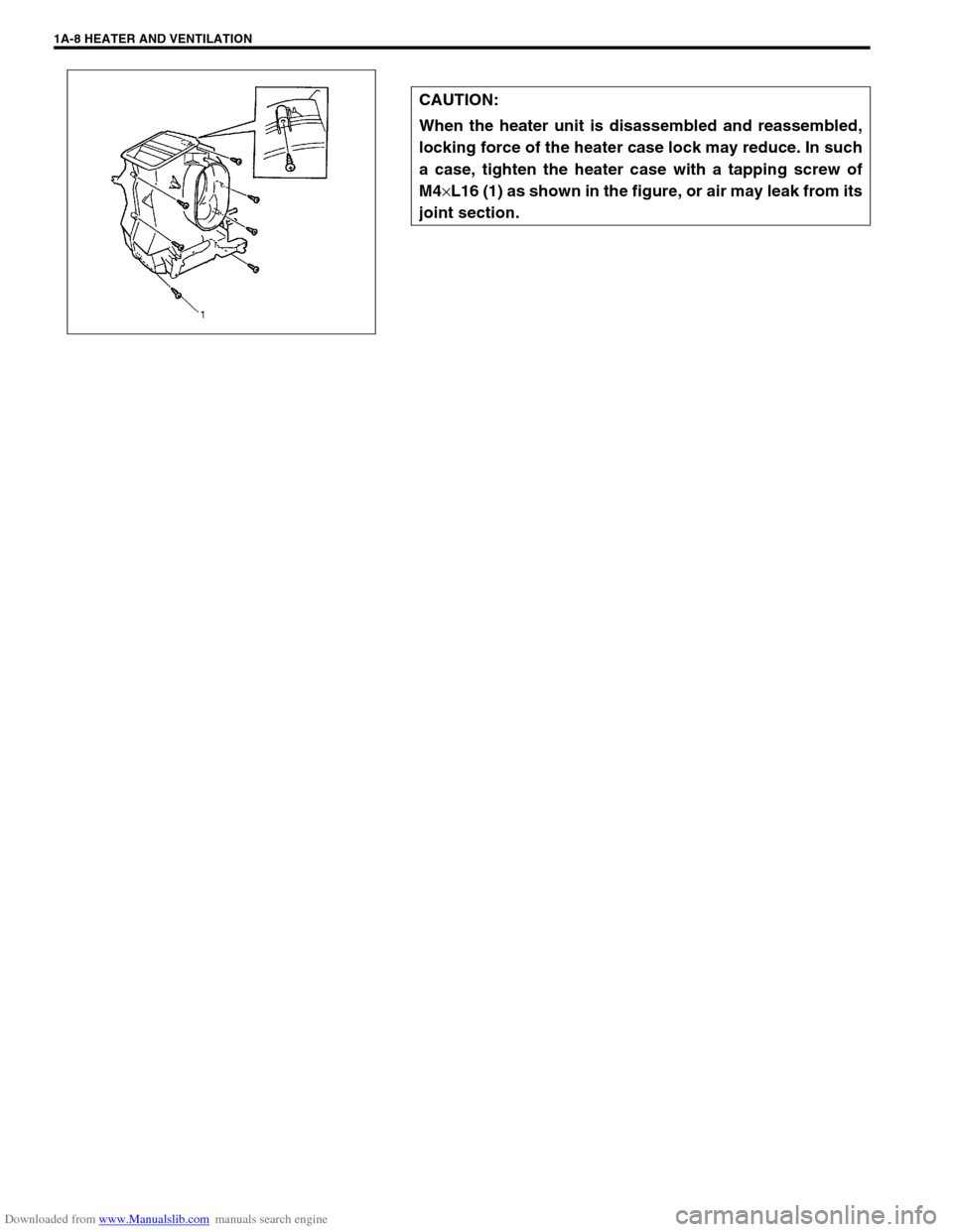
CAUTION:
When the heater unit is disassembled and reassembled,
locking force of the heater case lock may reduce. In such
a case, tighten the heater case with a tapping screw of
M4
×L16 (1) as shown in the figure, or air may leak from its
joint section.