rod end SUZUKI JIMNY 2005 3.G Service User Guide
[x] Cancel search | Manufacturer: SUZUKI, Model Year: 2005, Model line: JIMNY, Model: SUZUKI JIMNY 2005 3.GPages: 687, PDF Size: 13.38 MB
Page 124 of 687
Downloaded from www.Manualslib.com manuals search engine STEERING GEAR BOX (MANUAL TYPE) AND LINKAGE 3B-3
Diagnosis
Diagnosis Table
Refer to “Diagnosis Table” in Section 3.
Steering Wheel Play Check
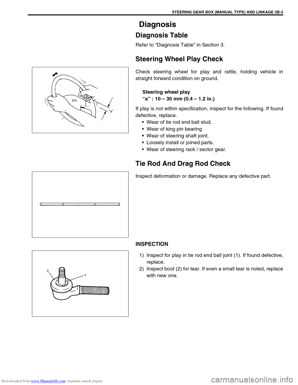
Check steering wheel for play and rattle, holding vehicle in
straight forward condition on ground.
Steering wheel play
“a” : 10 – 30 mm (0.4 – 1.2 in.)
If play is not within specification, inspect for the following. If found
defective, replace.
Wear of tie rod end ball stud.
Wear of king pin bearing
Wear of steering shaft joint.
Loosely install or joined parts.
Wear of steering rack / sector gear.
Tie Rod And Drag Rod Check
Inspect deformation or damage. Replace any defective part.
INSPECTION
1) Inspect for play in tie rod end ball joint (1). If found defective,
replace.
2) Inspect boot (2) for tear. If even a small tear is noted, replace
with new one.
Page 127 of 687
Downloaded from www.Manualslib.com manuals search engine 3B-6 STEERING GEAR BOX (MANUAL TYPE) AND LINKAGE
On-Vehicle Service
Steering Gear Box
REMOVAL
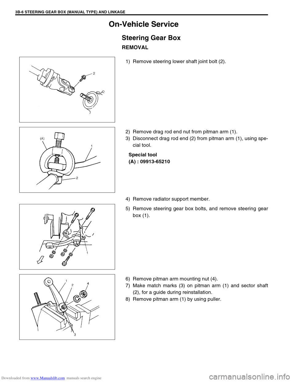
1) Remove steering lower shaft joint bolt (2).
2) Remove drag rod end nut from pitman arm (1).
3) Disconnect drag rod end (2) from pitman arm (1), using spe-
cial tool.
Special tool
(A) : 09913-65210
4) Remove radiator support member.
5) Remove steering gear box bolts, and remove steering gear
box (1).
6) Remove pitman arm mounting nut (4).
7) Make match marks (3) on pitman arm (1) and sector shaft
(2), for a guide during reinstallation.
8) Remove pitman arm (1) by using puller.
Page 128 of 687
Downloaded from www.Manualslib.com manuals search engine STEERING GEAR BOX (MANUAL TYPE) AND LINKAGE 3B-7
INSTALLATION
Reverse removal procedure to install steering gear box.
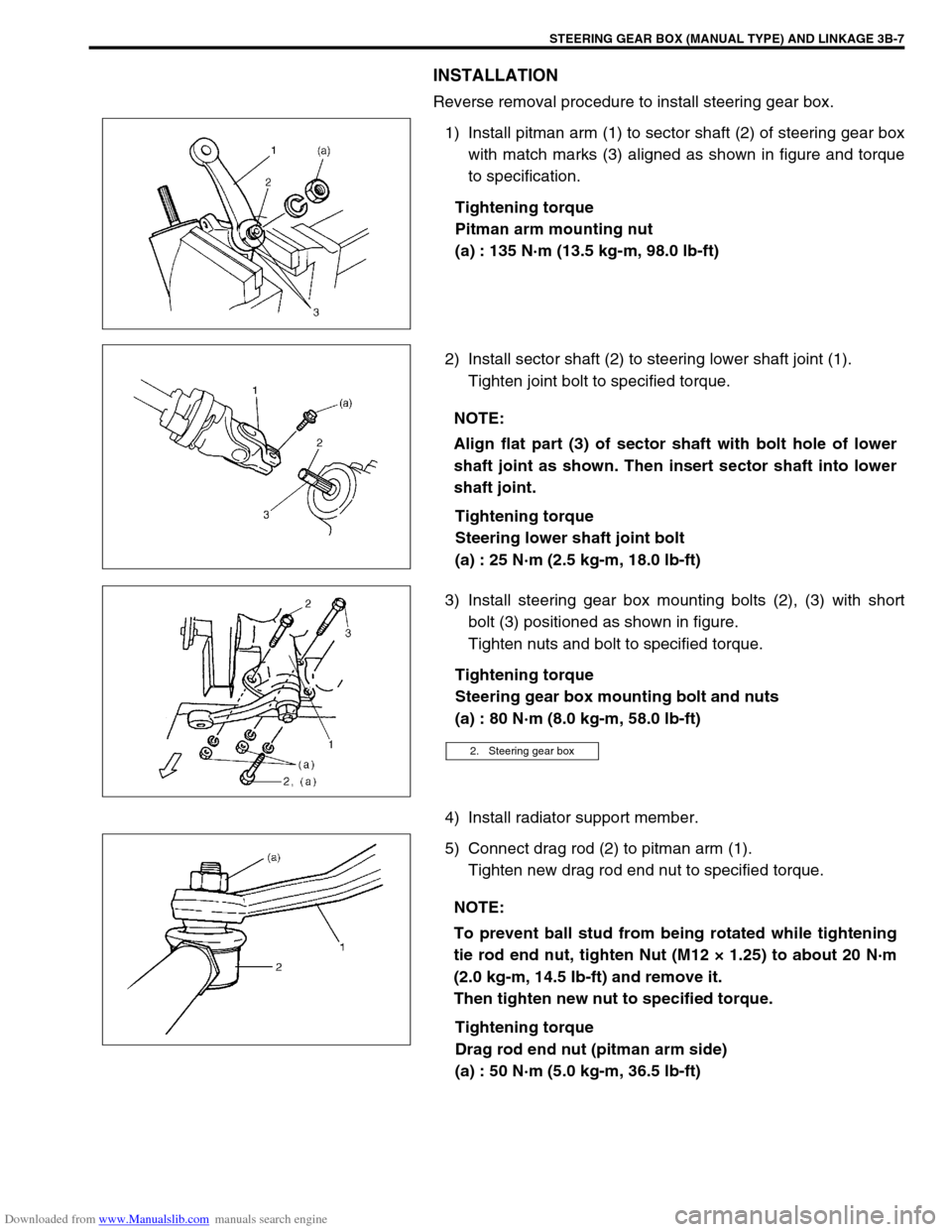
1) Install pitman arm (1) to sector shaft (2) of steering gear box
with match marks (3) aligned as shown in figure and torque
to specification.
Tightening torque
Pitman arm mounting nut
(a) : 135 N·m (13.5 kg-m, 98.0 lb-ft)
2) Install sector shaft (2) to steering lower shaft joint (1).
Tighten joint bolt to specified torque.
Tightening torque
Steering lower shaft joint bolt
(a) : 25 N·m (2.5 kg-m, 18.0 lb-ft)
3) Install steering gear box mounting bolts (2), (3) with short
bolt (3) positioned as shown in figure.
Tighten nuts and bolt to specified torque.
Tightening torque
Steering gear box mounting bolt and nuts
(a) : 80 N·m (8.0 kg-m, 58.0 lb-ft)
4) Install radiator support member.
5) Connect drag rod (2) to pitman arm (1).
Tighten new drag rod end nut to specified torque.
Tightening torque
Drag rod end nut (pitman arm side)
(a) : 50 N·m (5.0 kg-m, 36.5 lb-ft)
NOTE:
Align flat part (3) of sector shaft with bolt hole of lower
shaft joint as shown. Then insert sector shaft into lower
shaft joint.
2. Steering gear box
NOTE:
To prevent ball stud from being rotated while tightening
tie rod end nut, tighten Nut (M12 × 1.25) to about 20 N·m
(2.0 kg-m, 14.5 Ib-ft) and remove it.
Then tighten new nut to specified torque.
Page 129 of 687
Downloaded from www.Manualslib.com manuals search engine 3B-8 STEERING GEAR BOX (MANUAL TYPE) AND LINKAGE
Tie Rod And Drag Rod
REMOVAL
1) Hoist vehicle and remove wheel (s).
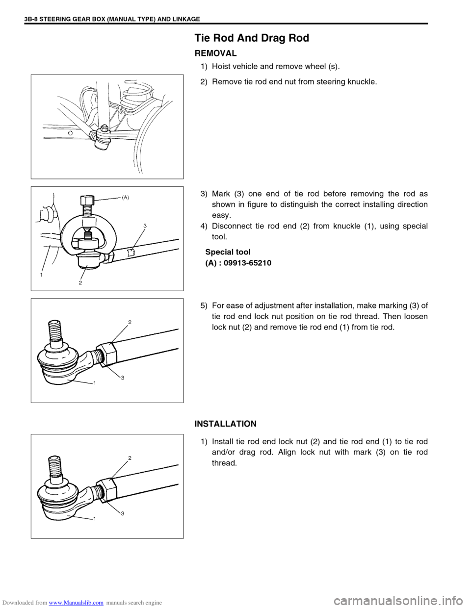
2) Remove tie rod end nut from steering knuckle.
3) Mark (3) one end of tie rod before removing the rod as
shown in figure to distinguish the correct installing direction
easy.
4) Disconnect tie rod end (2) from knuckle (1), using special
tool.
Special tool
(A) : 09913-65210
5) For ease of adjustment after installation, make marking (3) of
tie rod end lock nut position on tie rod thread. Then loosen
lock nut (2) and remove tie rod end (1) from tie rod.
INSTALLATION
1) Install tie rod end lock nut (2) and tie rod end (1) to tie rod
and/or drag rod. Align lock nut with mark (3) on tie rod
thread.
Page 130 of 687
Downloaded from www.Manualslib.com manuals search engine STEERING GEAR BOX (MANUAL TYPE) AND LINKAGE 3B-9
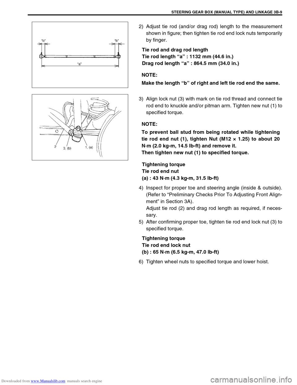
2) Adjust tie rod (and/or drag rod) length to the measurement
shown in figure; then tighten tie rod end lock nuts temporarily
by finger.
Tie rod and drag rod length
Tie rod length “a” : 1132 mm (44.6 in.)
Drag rod length “a” : 864.5 mm (34.0 in.)
3) Align lock nut (3) with mark on tie rod thread and connect tie
rod end to knuckle and/or pitman arm. Tighten new nut (1) to
specified torque.
Tightening torque
Tie rod end nut
(a) : 43 N·m (4.3 kg-m, 31.5 lb-ft)
4) Inspect for proper toe and steering angle (inside & outside).
(Refer to “Preliminary Checks Prior To Adjusting Front Align-
ment” in Section 3A).
Adjust tie rod (2) and drag rod length as required, if neces-
sary.
5) After confirming proper toe, tighten tie rod end lock nut (3) to
specified torque.
Tightening torque
Tie rod end lock nut
(b) : 65 N·m (6.5 kg-m, 47.0 lb-ft)
6) Tighten wheel nuts to specified torque and lower hoist.NOTE:
Make the length “b” of right and left tie rod end the same.
NOTE:
To prevent ball stud from being rotated while tightening
tie rod end nut (1), tighten Nut (M12 × 1.25) to about 20
N·m (2.0 kg-m, 14.5 Ib-ft) and remove it.
Then tighten new nut (1) to specified torque.
Page 131 of 687
Downloaded from www.Manualslib.com manuals search engine 3B-10 STEERING GEAR BOX (MANUAL TYPE) AND LINKAGE
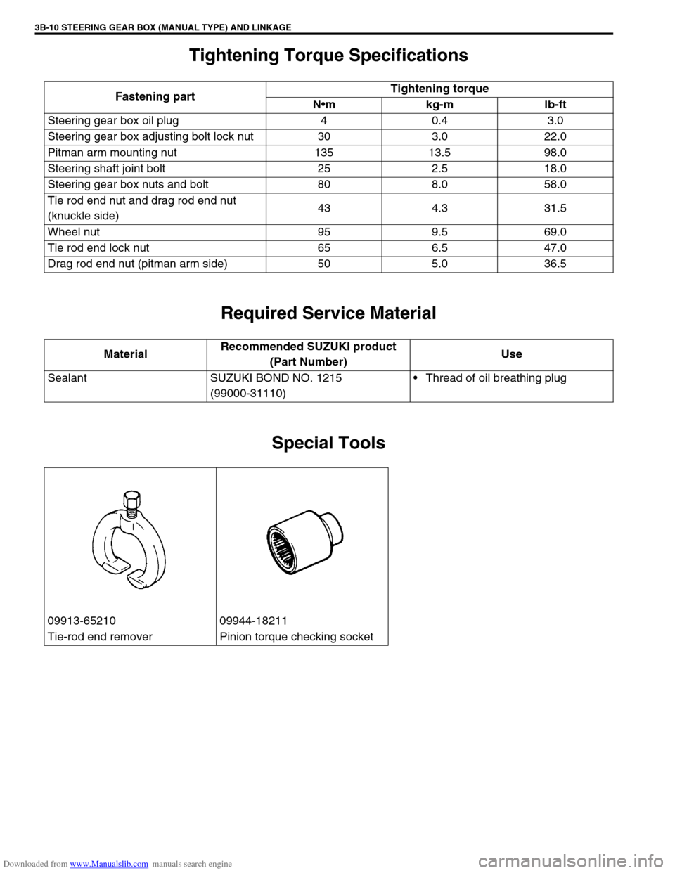
Tightening Torque Specifications
Required Service Material
Special Tools
Fastening partTightening torque
Nm kg-m lb-ft
Steering gear box oil plug 4 0.4 3.0
Steering gear box adjusting bolt lock nut 30 3.0 22.0
Pitman arm mounting nut 135 13.5 98.0
Steering shaft joint bolt 25 2.5 18.0
Steering gear box nuts and bolt 80 8.0 58.0
Tie rod end nut and drag rod end nut
(knuckle side)43 4.3 31.5
Wheel nut 95 9.5 69.0
Tie rod end lock nut 65 6.5 47.0
Drag rod end nut (pitman arm side) 50 5.0 36.5
MaterialRecommended SUZUKI product
(Part Number)Use
Sealant SUZUKI BOND NO. 1215
(99000-31110)Thread of oil breathing plug
09913-65210 09944-18211
Tie-rod end remover Pinion torque checking socket
Page 152 of 687
Downloaded from www.Manualslib.com manuals search engine POWER STEERING (P/S) SYSTEM (If equipped) 3B1-21
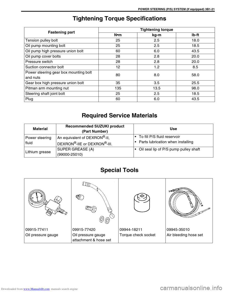
Tightening Torque Specifications
Required Service Materials
Special Tools
Fastening partTightening torque
Nm kg-m lb-ft
Tension pulley bolt 25 2.5 18.0
Oil pump mounting bolt 25 2.5 18.5
Oil pump high pressure union bolt 60 6.0 43.5
Oil pump cover bolts 28 2.8 20.0
Pressure switch 28 2.8 20.0
Suction connector bolt 12 1.2 8.5
Power steering gear box mounting bolt
and nuts80 8.0 58.0
Gear box high pressure union bolt 35 3.5 25.5
Pitman arm mounting nut 135 13.5 98.0
Steering shaft joint bolt 25 2.5 18.5
Plug 60 6.0 43.5
MaterialRecommended SUZUKI product
(Part Number)Use
Power steering
fluidAn equivalent of DEXRON
®-II,
DEXRON
®-IIE or DEXRON®-III.To fill P/S fluid reservoir
Parts lubrication when installing
Lithium greaseSUPER GREASE (A)
(99000-25010)Oil seal lip of P/S pump pulley shaft
09915-77411 09915-77420 09944-18211 09945-35010
Oil pressure gauge Oil pressure gauge
attachment & hose setTorque check socket Air bleeding hose set
Page 172 of 687
Downloaded from www.Manualslib.com manuals search engine STEERING WHEEL AND COLUMN 3C-19
6) Check steering shaft joints and shaft for any damages such
as crack, breakage, malfunction or excessive play.
If anything is found faulty, replace as lower joint assembly or
column assembly.
7) Check steering shaft for smooth rotation.
If found defective, replace as column assembly.
8) Check steering shaft and column for bend, cracks or defor-
mation.
If found defective, replace.
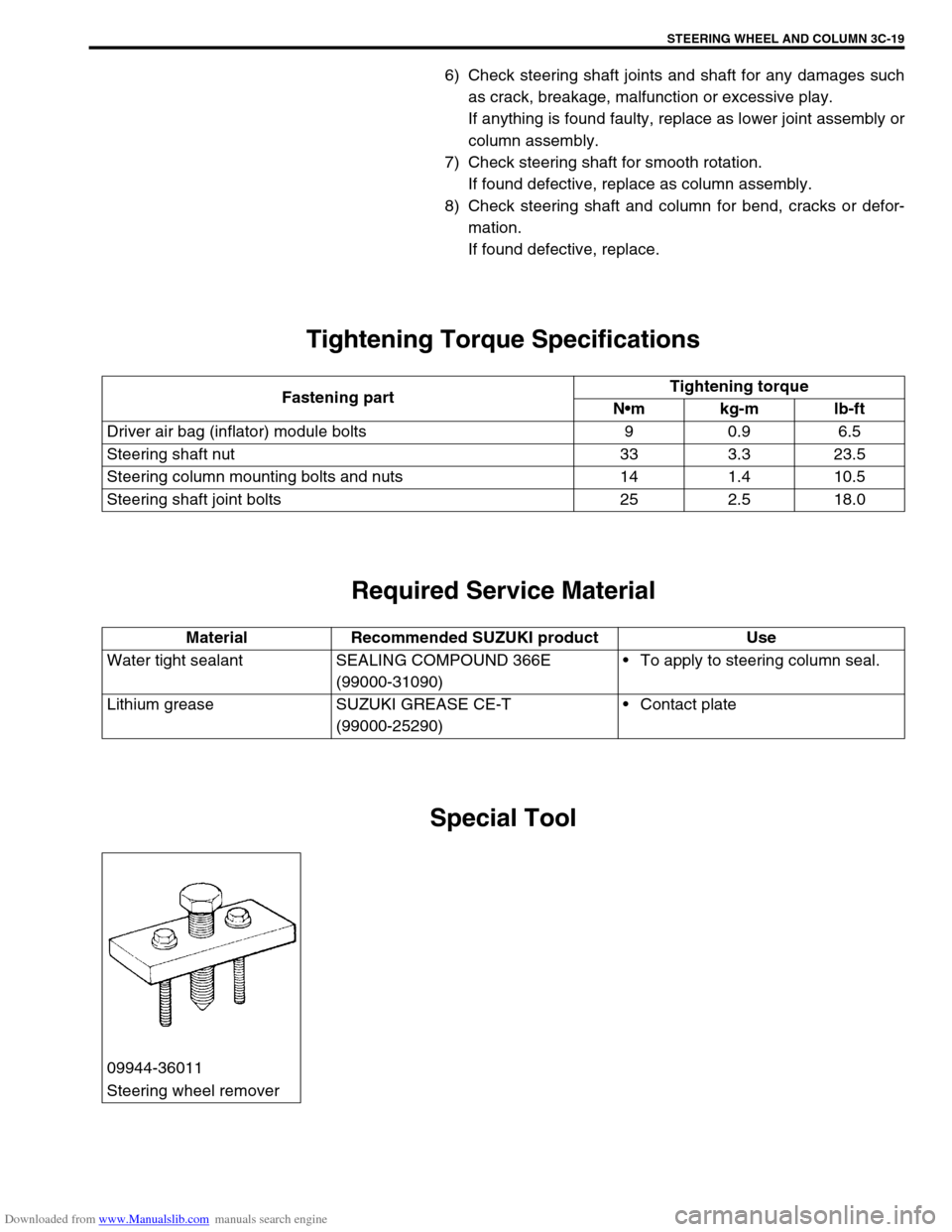
Tightening Torque Specifications
Required Service Material
Special Tool
Fastening partTightening torque
Nm kg-m lb-ft
Driver air bag (inflator) module bolts 9 0.9 6.5
Steering shaft nut 33 3.3 23.5
Steering column mounting bolts and nuts 14 1.4 10.5
Steering shaft joint bolts 25 2.5 18.0
Material Recommended SUZUKI product Use
Water tight sealant SEALING COMPOUND 366E
(99000-31090)To apply to steering column seal.
Lithium grease SUZUKI GREASE CE-T
(99000-25290)Contact plate
09944-36011
Steering wheel remover
Page 187 of 687

Downloaded from www.Manualslib.com manuals search engine 3D-14 FRONT SUSPENSION
Shock Absorber and/or Coil Spring Check
1) Inspect shock absorber for oil leakage. If shock absorber is
found faulty, replace it as an assembly unit, because it can
not be disassembled.
2) Shock absorber function check
Check and adjust tire pressures as specified.
Bounce body three or four times continuously by pushing
front end on the side with shock absorber to be checked.
Apply the same amount of force at each push and note
shock absorber resistance both when pushed and rebound-
ing.
Also, note how many times vehicle body rebounds before
coming to stop after hands are off. Do the same for shock
absorber on the other side.
Compare shock absorber resistance and number of rebound
on the right with those on the left.
And they must be equal in both. With proper shock absorber,
body should come to stop the moment hands are off or after
only one or two small rebounds. If shock absorbers are sus-
pected, compare them with known good vehicle or shock
absorber.
3) Inspect for damage or deformation.
4) Inspect for cracks or deformation in spring seat.
5) Inspect for deterioration of bump stopper.
6) Inspect shock absorber mount for wear, cracks or deforma-
tion.Replace any parts found defective in steps 2) – 6).
Leading Arm / Lateral Rod / Steering Knuckle
Check
Inspect for cracks, deformation or damage.
Page 196 of 687
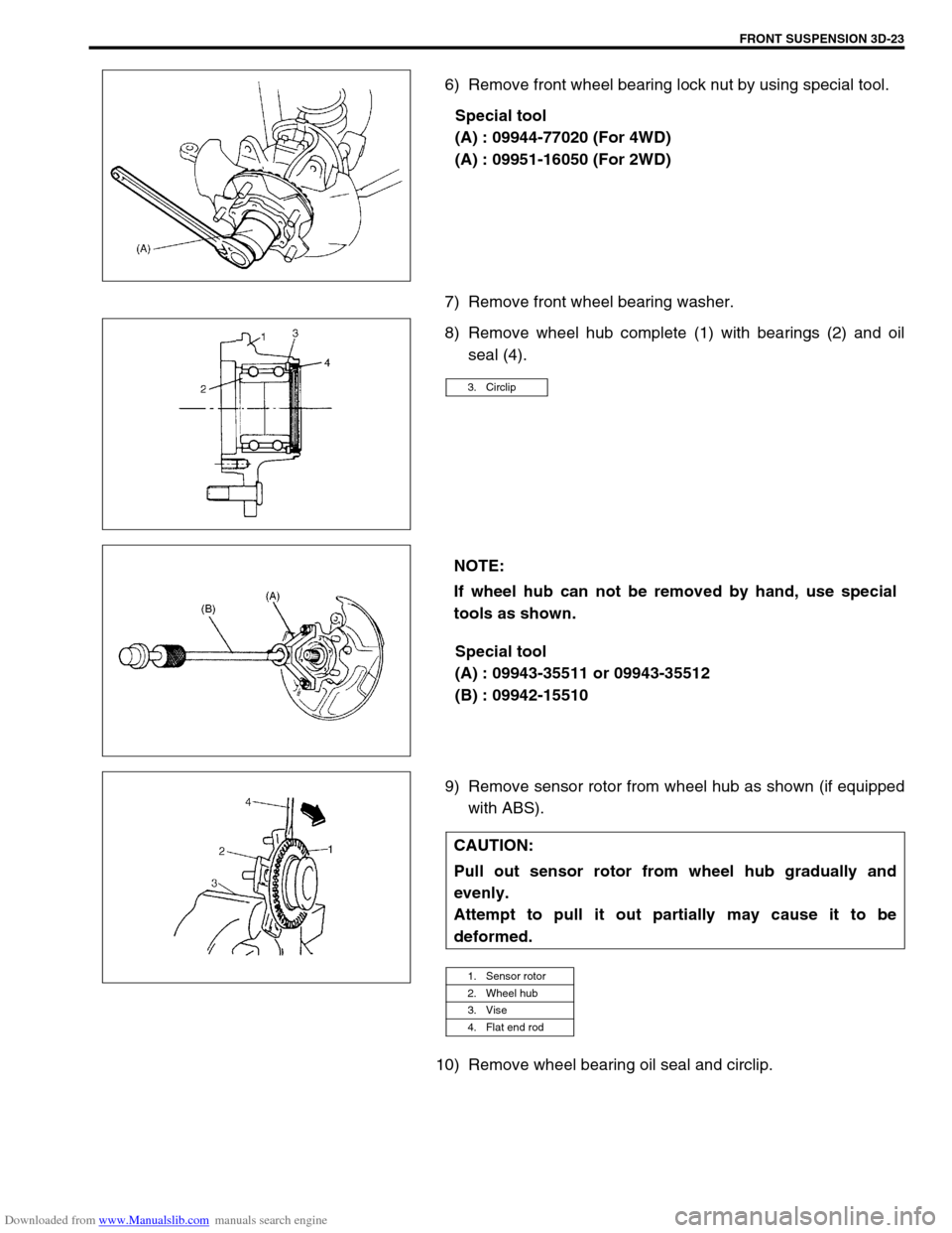
Downloaded from www.Manualslib.com manuals search engine FRONT SUSPENSION 3D-23
6) Remove front wheel bearing lock nut by using special tool.
Special tool
(A) : 09944-77020 (For 4WD)
(A) : 09951-16050 (For 2WD)
7) Remove front wheel bearing washer.
8) Remove wheel hub complete (1) with bearings (2) and oil
seal (4).
Special tool
(A) : 09943-35511 or 09943-35512
(B) : 09942-15510
9) Remove sensor rotor from wheel hub as shown (if equipped
with ABS).
10) Remove wheel bearing oil seal and circlip.
3. Circlip
NOTE:
If wheel hub can not be removed by hand, use special
tools as shown.
CAUTION:
Pull out sensor rotor from wheel hub gradually and
evenly.
Attempt to pull it out partially may cause it to be
deformed.
1. Sensor rotor
2. Wheel hub
3. Vise
4. Flat end rod