ect SUZUKI JIMNY 2005 3.G Service Workshop Manual
[x] Cancel search | Manufacturer: SUZUKI, Model Year: 2005, Model line: JIMNY, Model: SUZUKI JIMNY 2005 3.GPages: 687, PDF Size: 13.38 MB
Page 236 of 687
Downloaded from www.Manualslib.com manuals search engine REAR SUSPENSION 3E-17
16) Upon completion of all jobs, depress brake pedal with about
30 kg (66 lbs) load over ten times so as to obtain proper
drum-to shoe clearance.
Adjust parking brake cable. (For adjustment, refer to “Parking
Brake Check and Adjustment” in Section 5.)
17) Tighten parking brake lever cover screws.
18) Check to ensure that brake drum is free from dragging and
proper braking is obtained. Then remove vehicle from hoist
and perform brake test (foot brake and parking brake).
19) Check each installed part for oil leakage.
Rear Axle Shaft Inner Oil Seal
REMOVAL
1) Remove rear axle shaft. For details, refer to “Rear Axle Shaft
and Wheel Bearing” in this section.
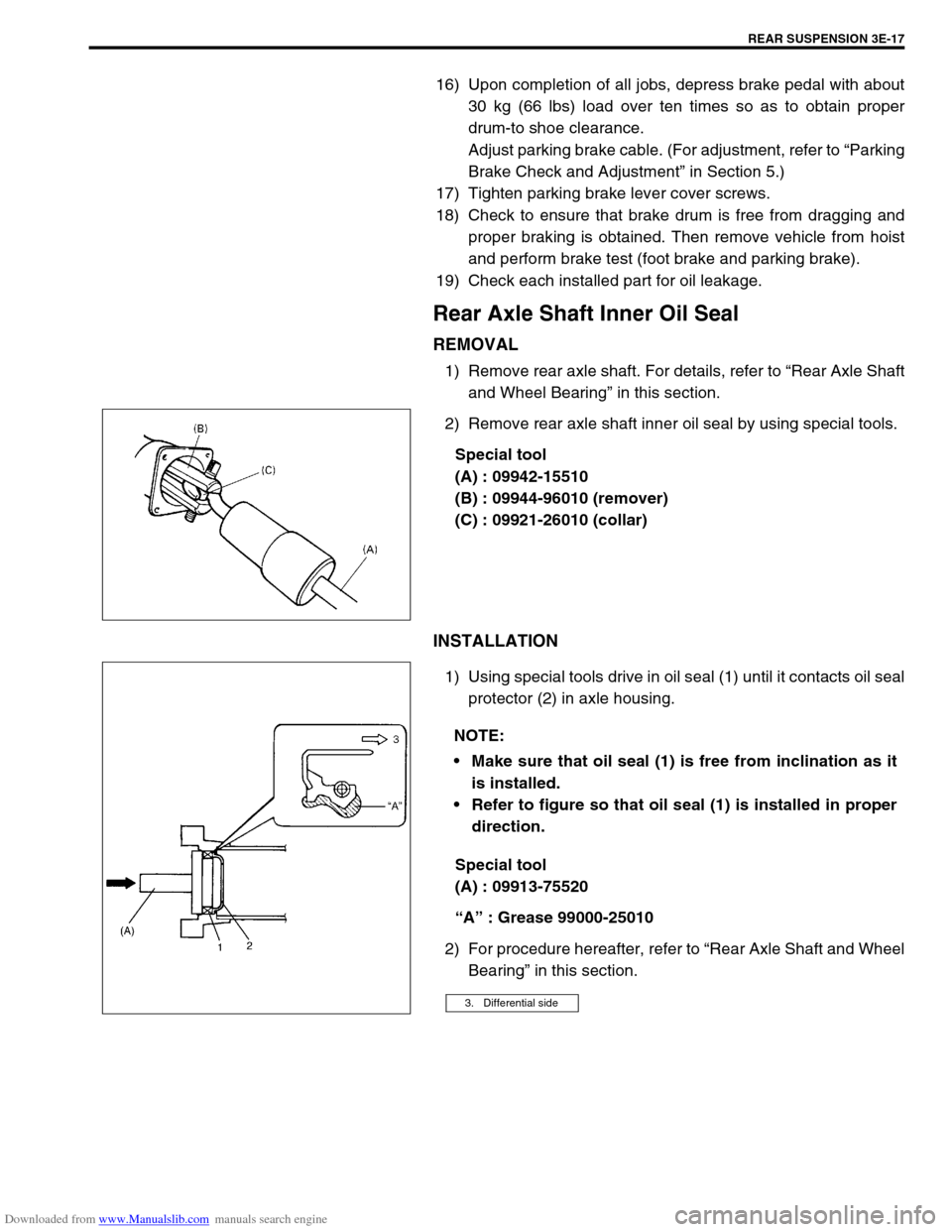
2) Remove rear axle shaft inner oil seal by using special tools.
Special tool
(A) : 09942-15510
(B) : 09944-96010 (remover)
(C) : 09921-26010 (collar)
INSTALLATION
1) Using special tools drive in oil seal (1) until it contacts oil seal
protector (2) in axle housing.
Special tool
(A) : 09913-75520
“A” : Grease 99000-25010
2) For procedure hereafter, refer to “Rear Axle Shaft and Wheel
Bearing” in this section.
NOTE:
Make sure that oil seal (1) is free from inclination as it
is installed.
Refer to figure so that oil seal (1) is installed in proper
direction.
3. Differential side
Page 237 of 687
Downloaded from www.Manualslib.com manuals search engine 3E-18 REAR SUSPENSION
Rear Axle Housing
REMOVAL
1) Hoist vehicle and remove wheels.
2) Remove rear axle shaft, refer to “Rear Axle Shaft and Wheel
Bearing” in this section.
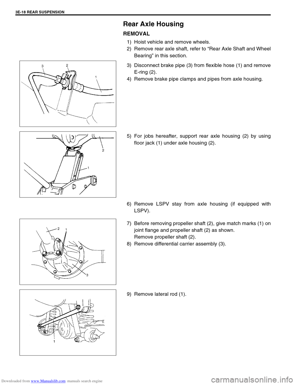
3) Disconnect brake pipe (3) from flexible hose (1) and remove
E-ring (2).
4) Remove brake pipe clamps and pipes from axle housing.
5) For jobs hereafter, support rear axle housing (2) by using
floor jack (1) under axle housing (2).
6) Remove LSPV stay from axle housing (if equipped with
LSPV).
7) Before removing propeller shaft (2), give match marks (1) on
joint flange and propeller shaft (2) as shown.
Remove propeller shaft (2).
8) Remove differential carrier assembly (3).
9) Remove lateral rod (1).
Page 238 of 687

Downloaded from www.Manualslib.com manuals search engine REAR SUSPENSION 3E-19
10) Loosen rear mounting nuts of trailing arm (2) but don’t
remove bolt.
11) Remove shock absorber (1) lower mounting bolt.
12) Lower floor jack until tension of suspension coil spring
becomes a little loose and remove rear mount bolts of trailing
arm.
13) Lower rear axle housing gradually.
14) Remove axle housing.
INSTALLATION
Install removed parts in reverse order of removal, noting the fol-
lowing.
1) Place rear axle housing (1) on floor jack. Then install trailing
arm (2) rear mounting bolts (right & left) in proper direction
as shown. At this time, mount nuts but don’t tighten them.
2) Install coil spring (2) (right & left) on spring seat (1) of axle
housing and raise axle housing.
3. Out side
4. Body center
NOTE:
Upper and lower diameters of coil spring (2) are differ-
ent. Bring larger diameter end at bottom and set its
open end in place on spring seat (1).
When seating coil spring (2), mate spring end with
stepped part (3) of rear axle spring seat (1) as shown.
A: Upper side (small dia.)
B: Lower side (large dia.)
Page 239 of 687
Downloaded from www.Manualslib.com manuals search engine 3E-20 REAR SUSPENSION
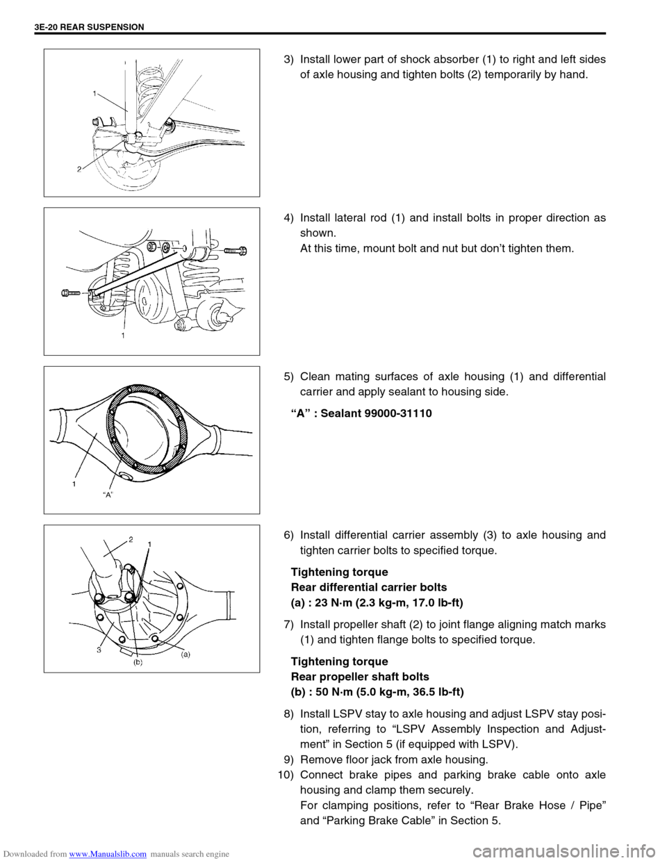
3) Install lower part of shock absorber (1) to right and left sides
of axle housing and tighten bolts (2) temporarily by hand.
4) Install lateral rod (1) and install bolts in proper direction as
shown.
At this time, mount bolt and nut but don’t tighten them.
5) Clean mating surfaces of axle housing (1) and differential
carrier and apply sealant to housing side.
“A” : Sealant 99000-31110
6) Install differential carrier assembly (3) to axle housing and
tighten carrier bolts to specified torque.
Tightening torque
Rear differential carrier bolts
(a) : 23 N·m (2.3 kg-m, 17.0 lb-ft)
7) Install propeller shaft (2) to joint flange aligning match marks
(1) and tighten flange bolts to specified torque.
Tightening torque
Rear propeller shaft bolts
(b) : 50 N·m (5.0 kg-m, 36.5 lb-ft)
8) Install LSPV stay to axle housing and adjust LSPV stay posi-
tion, referring to “LSPV Assembly Inspection and Adjust-
ment” in Section 5 (if equipped with LSPV).
9) Remove floor jack from axle housing.
10) Connect brake pipes and parking brake cable onto axle
housing and clamp them securely.
For clamping positions, refer to “Rear Brake Hose / Pipe”
and “Parking Brake Cable” in Section 5.
Page 240 of 687
Downloaded from www.Manualslib.com manuals search engine REAR SUSPENSION 3E-21
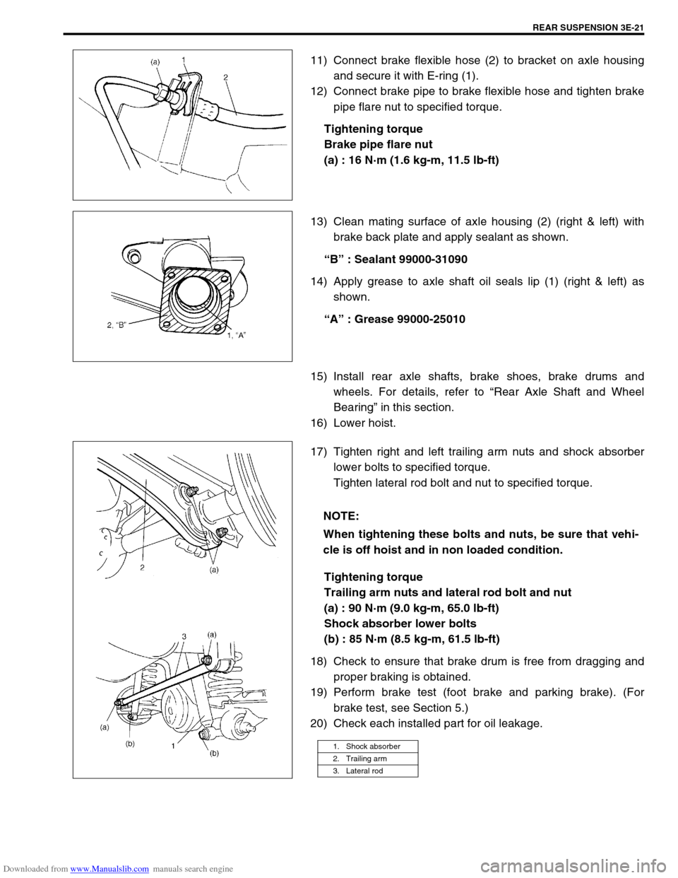
11) Connect brake flexible hose (2) to bracket on axle housing
and secure it with E-ring (1).
12) Connect brake pipe to brake flexible hose and tighten brake
pipe flare nut to specified torque.
Tightening torque
Brake pipe flare nut
(a) : 16 N·m (1.6 kg-m, 11.5 lb-ft)
13) Clean mating surface of axle housing (2) (right & left) with
brake back plate and apply sealant as shown.
“B” : Sealant 99000-31090
14) Apply grease to axle shaft oil seals lip (1) (right & left) as
shown.
“A” : Grease 99000-25010
15) Install rear axle shafts, brake shoes, brake drums and
wheels. For details, refer to “Rear Axle Shaft and Wheel
Bearing” in this section.
16) Lower hoist.
17) Tighten right and left trailing arm nuts and shock absorber
lower bolts to specified torque.
Tighten lateral rod bolt and nut to specified torque.
Tightening torque
Trailing arm nuts and lateral rod bolt and nut
(a) : 90 N·m (9.0 kg-m, 65.0 lb-ft)
Shock absorber lower bolts
(b) : 85 N·m (8.5 kg-m, 61.5 lb-ft)
18) Check to ensure that brake drum is free from dragging and
proper braking is obtained.
19) Perform brake test (foot brake and parking brake). (For
brake test, see Section 5.)
20) Check each installed part for oil leakage.
NOTE:
When tightening these bolts and nuts, be sure that vehi-
cle is off hoist and in non loaded condition.
1. Shock absorber
2. Trailing arm
3. Lateral rod
Page 241 of 687

Downloaded from www.Manualslib.com manuals search engine 3E-22 REAR SUSPENSION
Tightening Torque Specifications
Required Service Materials
Fastening portionTightening torque
Nm kg-m lb-ft
Shock absorber upper and lower bolt 85 8.5 61.5
Bump stopper 50 5.0 36.5
Lateral rod bolt and nut
90 9.0 65.0
Trailing arm nut (Front and Rear)
Brake back plate nut 23 2.3 17.0
Brake pipe flare nut 16 1.6 11.5
Rear differential carrier bolt 23 2.3 17.0
Rear propeller shaft bolt (Differential case side) 50 5.0 36.5
Rear propeller shaft bolt (Shaft No.3 transfer case side) 33 3.3 24.0
Wheel nut 95 9.5 69.0
Wheel speed sensor bolt and harness clamp bolt 10 1.0 7.5
MaterialRecommended SUZUKI product
(Part Number)Use
Lithium greaseSUZUKI SUPER GREASE A
(99000-25010)Oil seal lip
SealantSUZUKI BOND NO. 1215
(99000-31110)Joint seam of differential carrier and
axle housing
Water tight sealantSEALING COMPOUND 366E
(99000-31090)To apply to mating surfaces of brake
back plate and rear axle.
Gear oilFor gear oil information, refer to “Mainte-
nance Service” in Section 7E of this manual.Differential gear
(Rear axle housing)
Page 244 of 687
Downloaded from www.Manualslib.com manuals search engine WHEELS AND TIRES 3F-1
6F1
6F2
6G
3F
8A
8B
8C
8B
8C
8D
8E
9
10
10A
10B
SECTION 3F
WHEELS AND TIRES
CONTENTS
General Description ........................................ 3F-2
Tires .............................................................. 3F-2
Wheels .......................................................... 3F-2
Replacement Tires ........................................ 3F-2
Replacement Wheels ................................ 3F-3
How To Measure Wheel Runout ............... 3F-3
Metric Lug Nuts and Wheel Studs ............. 3F-3
Diagnosis ......................................................... 3F-4
Diagnosis Table ............................................ 3F-4
Balancing Wheels ......................................... 3F-4
General Balance Procedure .......................... 3F-4
Off-vehicle balancing ................................. 3F-4
On-vehicle balancing ................................. 3F-4
Maintenance and Minor Adjustments ........... 3F-6Wheel and Tire.............................................. 3F-6
Studs ......................................................... 3F-6
Matched tires and wheels
(For vehicle equipped with steel
wheels) ...................................................... 3F-6
Inflation of Tires ............................................ 3F-6
Tire placard ............................................... 3F-7
Tire rotation ............................................... 3F-7
On-Vehicle Service ......................................... 3F-8
Wheel ............................................................ 3F-8
Tire ................................................................ 3F-9
Mounting and demounting......................... 3F-9
Repair........................................................ 3F-9
NOTE:
All wheel fasteners are important attaching parts in that they could affect the performance of vital
parts and systems, and/or could result in major repair expense. They must be replaced with one of the
same part number or with an equivalent part if replacement becomes necessary. Do not use a replace-
ment part of lesser quality or substitute design. Torque values must be used as specified during reas-
sembly to assure proper retention of all parts.
There is to be no welding as it may result in extensive damage and weakening of the metal.
Page 245 of 687

Downloaded from www.Manualslib.com manuals search engine 3F-2 WHEELS AND TIRES
General Description
Tires
This vehicle is equipped with following tire.
Tire size
: 205/70 R15 or 175/80 R15
The tires are of tubeless type. The tires are designed to operate satisfactorily with loads up to the full rated load
capacity when inflated to the recommended inflation pressure.
Correct tire pressures and driving habits have an important influence on tire life Heavy cornering, excessively
rapid acceleration, and unnecessary sharp braking increase tire wear.
Wheels
Standard equipment wheels are following steel wheels.
15 x 5 1/2 JJ
Replacement Tires
When replacement is necessary, the original equipment type tire should be used. Refer to the Tire Placard.
Replacement tires should be of the same size, load range and construction as those originally on the vehicle.
Use of any other size or type tire may affect ride, handling, speedometer / odometer calibration, vehicle ground
clearance and tire or snow chain clearance to the body and chassis.
It is recommended that new tires be installed in pairs on the same axle. If necessary to replace only one tire, it
should be paired with the tire having the most tread, to equalize braking traction.
The metric term for tire inflation pressure is the kilopascal (kPa).
Tire pressures will usually be printed in both kPa and psi on the
Tire Placard. Metric tire gauges are available from tool suppliers.
The following chart, converts commonly used inflation pressures
from kPa to psi. WARNING:
Do not mix different types of tires on the same vehicle such as radial, bias and bias-belted tires except
in emergencies, because vehicle handling may be seriously affected and may result in loss of control.
kPa
kgf/cm2psi
160
180
200
220
240
260
280
300
320
3401.6
1.8
2.0
2.2
2.4
2.6
2.8
3.0
3.2
3.423
26
29
32
35
38
41
44
47
50
Page 246 of 687
Downloaded from www.Manualslib.com manuals search engine WHEELS AND TIRES 3F-3
Replacement Wheels
Wheels must be replaced if they are bent, dented, have excessive
lateral or radial runout, leak air through welds, have elongated
bolt holes, if lug nuts won’t stay tight, or if they are heavily rusted.
Wheels with greater runout than shown in “How to Measure
Wheel Runout” may cause objectional vibrations.
Wheels for replacement must be equivalent to the originally
equipped wheels in load capacity, diameter, rim width, off-set and
mounting configuration. A wheel of improper size or type may
affect wheel and bearing life, brake cooling, speedometer / odom-
eter calibration, ground clearance to the body and chassis.
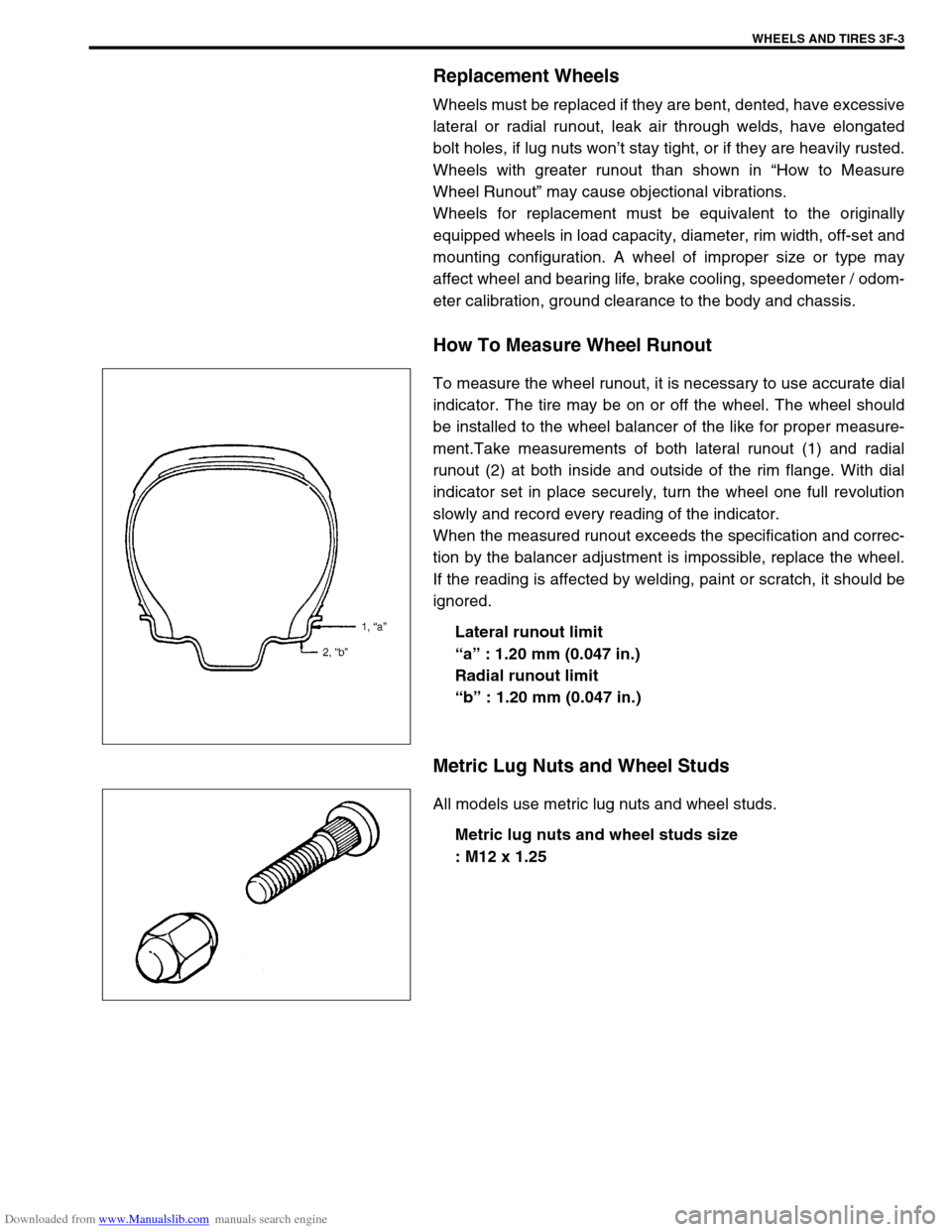
How To Measure Wheel Runout
To measure the wheel runout, it is necessary to use accurate dial
indicator. The tire may be on or off the wheel. The wheel should
be installed to the wheel balancer of the like for proper measure-
ment.Take measurements of both lateral runout (1) and radial
runout (2) at both inside and outside of the rim flange. With dial
indicator set in place securely, turn the wheel one full revolution
slowly and record every reading of the indicator.
When the measured runout exceeds the specification and correc-
tion by the balancer adjustment is impossible, replace the wheel.
If the reading is affected by welding, paint or scratch, it should be
ignored.
Lateral runout limit
“a” : 1.20 mm (0.047 in.)
Radial runout limit
“b” : 1.20 mm (0.047 in.)
Metric Lug Nuts and Wheel Studs
All models use metric lug nuts and wheel studs.
Metric lug nuts and wheel studs size
: M12 x 1.25
Page 247 of 687
Downloaded from www.Manualslib.com manuals search engine 3F-4 WHEELS AND TIRES
Diagnosis
Diagnosis Table
Refer to “Diagnosis Table” in Section 3.
Balancing Wheels
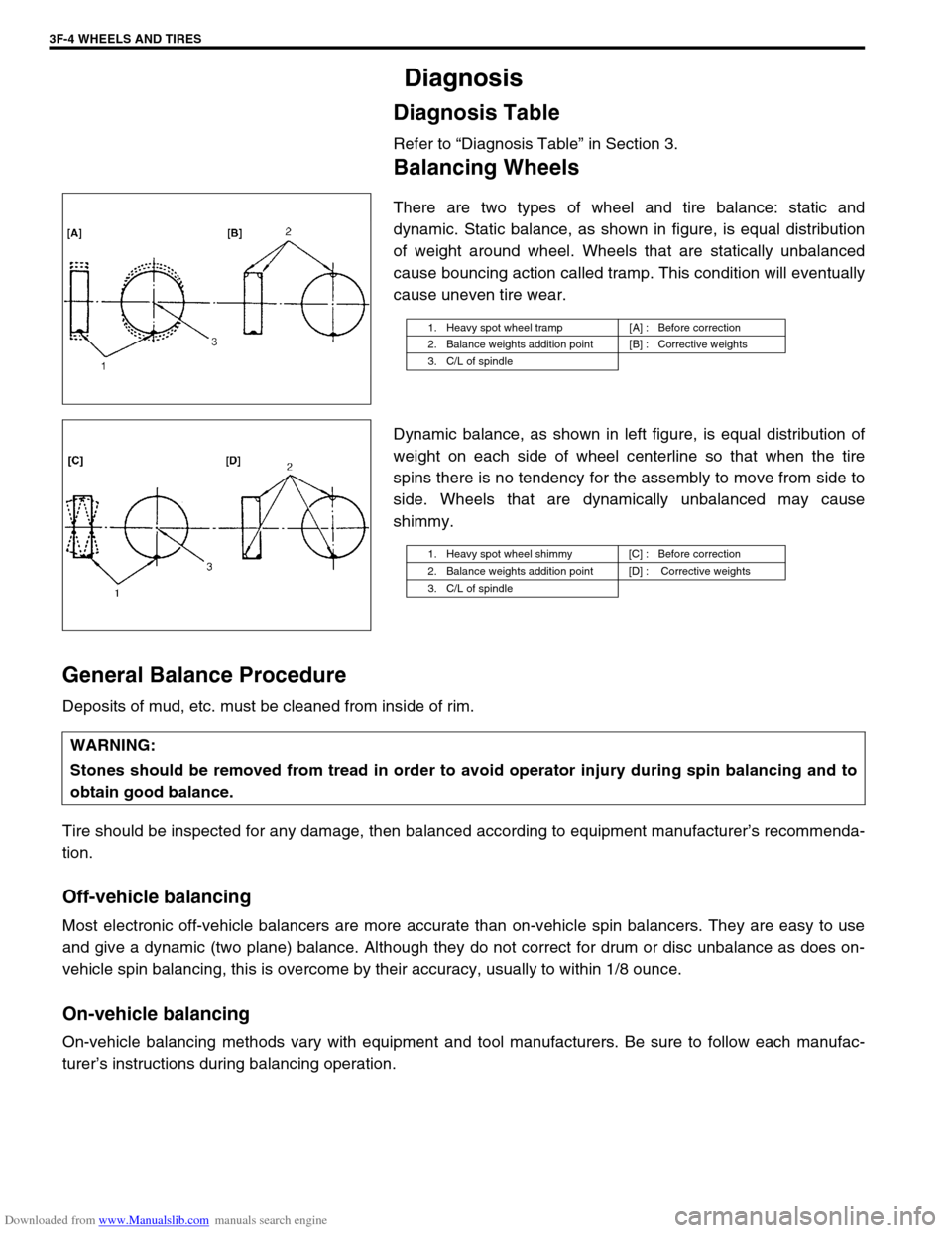
There are two types of wheel and tire balance: static and
dynamic. Static balance, as shown in figure, is equal distribution
of weight around wheel. Wheels that are statically unbalanced
cause bouncing action called tramp. This condition will eventually
cause uneven tire wear.
Dynamic balance, as shown in left figure, is equal distribution of
weight on each side of wheel centerline so that when the tire
spins there is no tendency for the assembly to move from side to
side. Wheels that are dynamically unbalanced may cause
shimmy.
General Balance Procedure
Deposits of mud, etc. must be cleaned from inside of rim.
Tire should be inspected for any damage, then balanced according to equipment manufacturer’s recommenda-
tion.
Off-vehicle balancing
Most electronic off-vehicle balancers are more accurate than on-vehicle spin balancers. They are easy to use
and give a dynamic (two plane) balance. Although they do not correct for drum or disc unbalance as does on-
vehicle spin balancing, this is overcome by their accuracy, usually to within 1/8 ounce.
On-vehicle balancing
On-vehicle balancing methods vary with equipment and tool manufacturers. Be sure to follow each manufac-
turer’s instructions during balancing operation.
1. Heavy spot wheel tramp [A] : Before correction
2. Balance weights addition point [B] : Corrective weights
3. C/L of spindle
1. Heavy spot wheel shimmy [C] : Before correction
2. Balance weights addition point [D] : Corrective weights
3. C/L of spindle
WARNING:
Stones should be removed from tread in order to avoid operator injury during spin balancing and to
obtain good balance.