relay SUZUKI JIMNY 2005 3.G Service Workshop Manual
[x] Cancel search | Manufacturer: SUZUKI, Model Year: 2005, Model line: JIMNY, Model: SUZUKI JIMNY 2005 3.GPages: 687, PDF Size: 13.38 MB
Page 14 of 687

Downloaded from www.Manualslib.com manuals search engine GENERAL INFORMATION 0A-9
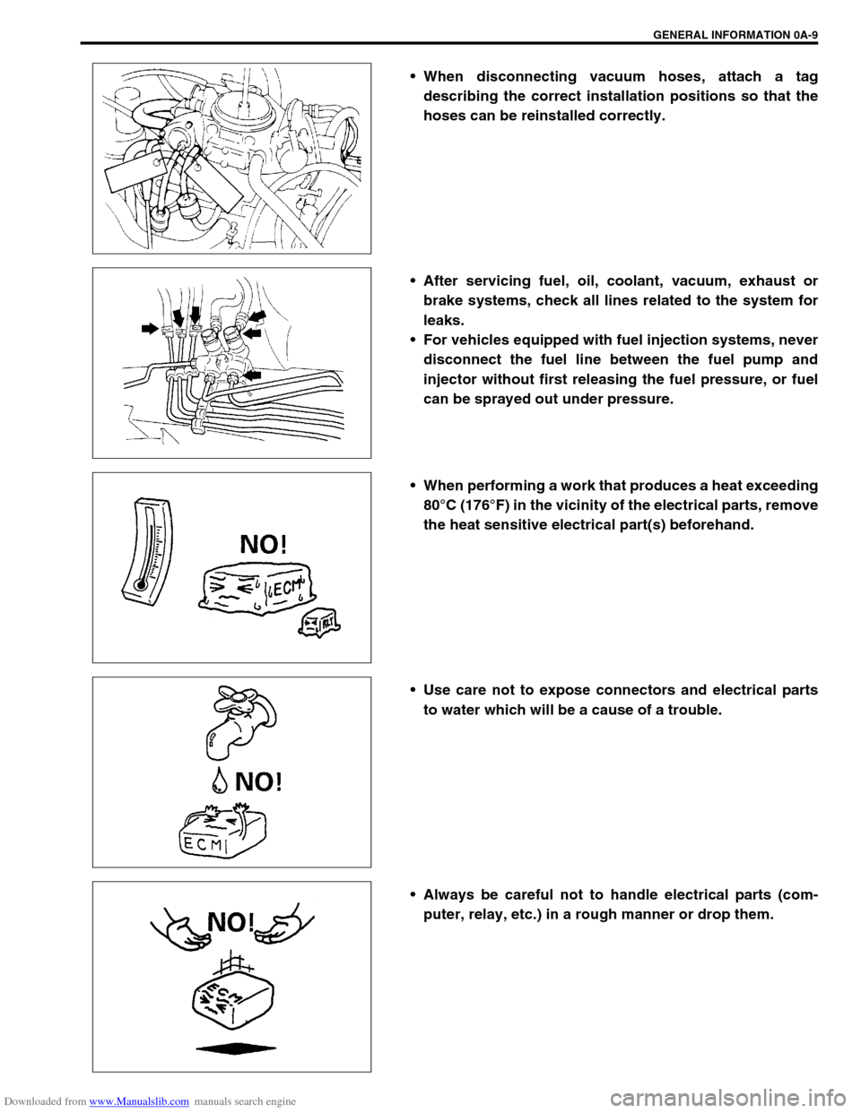
When disconnecting vacuum hoses, attach a tag
describing the correct installation positions so that the
hoses can be reinstalled correctly.
After servicing fuel, oil, coolant, vacuum, exhaust or
brake systems, check all lines related to the system for
leaks.
For vehicles equipped with fuel injection systems, never
disconnect the fuel line between the fuel pump and
injector without first releasing the fuel pressure, or fuel
can be sprayed out under pressure.
When performing a work that produces a heat exceeding
80°C (176°F) in the vicinity of the electrical parts, remove
the heat sensitive electrical part(s) beforehand.
Use care not to expose connectors and electrical parts
to water which will be a cause of a trouble.
Always be careful not to handle electrical parts (com-
puter, relay, etc.) in a rough manner or drop them.
Page 20 of 687

Downloaded from www.Manualslib.com manuals search engine GENERAL INFORMATION 0A-15
Short circuit check (wire harness to ground)
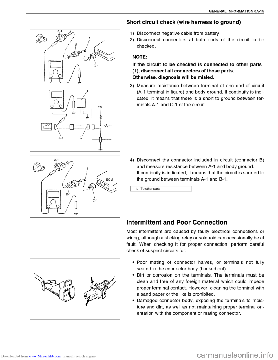
1) Disconnect negative cable from battery.
2) Disconnect connectors at both ends of the circuit to be
checked.
3) Measure resistance between terminal at one end of circuit
(A-1 terminal in figure) and body ground. If continuity is indi-
cated, it means that there is a short to ground between ter-
minals A-1 and C-1 of the circuit.
4) Disconnect the connector included in circuit (connector B)
and measure resistance between A-1 and body ground.
If continuity is indicated, it means that the circuit is shorted to
the ground between terminals A-1 and B-1.
Intermittent and Poor Connection
Most intermittent are caused by faulty electrical connections or
wiring, although a sticking relay or solenoid can occasionally be at
fault. When checking it for proper connection, perform careful
check of suspect circuits for:
Poor mating of connector halves, or terminals not fully
seated in the connector body (backed out).
Dirt or corrosion on the terminals. The terminals must be
clean and free of any foreign material which could impede
proper terminal contact. However, cleaning the terminal with
a sand paper or the like is prohibited.
Damaged connector body, exposing the terminals to mois-
ture and dirt, as well as not maintaining proper terminal ori-
entation with the component or mating connector. NOTE:
If the circuit to be checked is connected to other parts
(1), disconnect all connectors of those parts.
Otherwise, diagnosis will be misled.
1. To other parts
Page 63 of 687

Downloaded from www.Manualslib.com manuals search engine 1B-2 AIR CONDITIONING (OPTIONAL)
Evacuating ................................................. 1B-23
Evacuating procedure ............................ 1B-23
Charging .................................................... 1B-25
Charging procedure ............................... 1B-25
Removing Manifold Gauge Set .................. 1B-28
Leak Test ................................................... 1B-28
On-Vehicle Service ...................................... 1B-29
Service Precaution ..................................... 1B-29
Refrigerant line ....................................... 1B-29
Handling refrigerant HFC-134a
(R-134a) ................................................. 1B-30
Condenser Assembly ................................. 1B-31
Receiver / Dryer ......................................... 1B-32
Condenser Cooling Fan Assembly ............ 1B-33Cooling Unit (Evaporator) .......................... 1B-34
A/C Evaporator Thermistor (A/C Evaporator
Temperature Sensor)................................. 1B-37
Expansion Valve ........................................ 1B-37
Dual Pressure Switch ................................ 1B-38
A/C Switch ................................................. 1B-39
Condenser Cooling Fan Motor Relay ........ 1B-39
Compressor ............................................... 1B-39
Magnet Clutch............................................ 1B-41
Lip Type Seal ............................................. 1B-45
Tightening Torque Specification................ 1B-46
Required Service Materials ......................... 1B-47
Special Tools ............................................... 1B-47
Page 66 of 687

Downloaded from www.Manualslib.com manuals search engine AIR CONDITIONING (OPTIONAL) 1B-5
Diagnosis
General Diagnosis Table
Condition Possible Cause Correction
Cool air won’t come
out (A/C system won’t
operative)No refrigerant Perform recover, evacuation and charging.
Fuse blown Check fuses in main and circuit fuse
boxes, and check short circuit to ground.
A/C switch faulty Check A/C switch.
Blower fan switch faulty Check blower fan switch referring to Sec-
tion 1A.
A/C evaporator thermistor faulty Check A/C evaporator thermistor.
Dual pressure switch faulty Check dual pressure switch.
Wiring or grounding faulty Repair as necessary.
ECT sensor faulty Check ECT sensor referring to Section 6E.
ECM and its circuit faulty Check ECM and its circuit referring to Sec-
tion 6E.
4WD controller faulty Check 4WD controller referring to Section
3D.
Cool air won’t come
out (A/C compressor
won't operative)ECM faulty Check ECM and its circuit referring to Sec-
tion 6E.
Magnet clutch faulty Check magnet clutch.
Compressor drive belt loosen or broken Adjust or replace drive belt.
Compressor faulty Check compressor.
Cool air won’t come
out (A/C condenser
cooling fan motor
won’t operative)Fuse blown Check “A/C” fuse in main fuse box, and
check short circuit to ground.
Wiring or grounding faulty Repair as necessary.
Condenser cooling fan motor relay
faultyCheck condenser cooling fan motor relay.
Condenser cooling fan motor faulty Check condenser cooling fan motor.
Cool air won’t come
out (Blower fan motor
won’t operative)Fuse blown Check fuses in main and circuit fuse
boxes, and check short circuit to ground.
Blower fan motor resistor faulty Check blower fan motor resistor referring
to Section 1A.
Blower fan switch faulty Check blower fan switch referring to Sec-
tion 1A.
Wiring or grounding faulty Repair as necessary.
Blower fan motor faulty Check blower fan motor referring to Sec-
tion 1A.
Page 77 of 687
![SUZUKI JIMNY 2005 3.G Service Workshop Manual Downloaded from www.Manualslib.com manuals search engine 1B-16 AIR CONDITIONING (OPTIONAL)
Electronical Diagnosis
Wiring Diagram
[A]: 4WD model 4. Dual pressure switch 9. Thermal switch 14. Circuit fu SUZUKI JIMNY 2005 3.G Service Workshop Manual Downloaded from www.Manualslib.com manuals search engine 1B-16 AIR CONDITIONING (OPTIONAL)
Electronical Diagnosis
Wiring Diagram
[A]: 4WD model 4. Dual pressure switch 9. Thermal switch 14. Circuit fu](/img/20/7588/w960_7588-76.png)
Downloaded from www.Manualslib.com manuals search engine 1B-16 AIR CONDITIONING (OPTIONAL)
Electronical Diagnosis
Wiring Diagram
[A]: 4WD model 4. Dual pressure switch 9. Thermal switch 14. Circuit fuse box
[B]: 2WD model 5. 4WD controller 10. Ignition switch 15. Main fuse box
1. Blower fan motor 6. Condenser cooling fan motor relay 11. A/C evaporator thermistor 16. Generator
2. Blower fan motor resistor 7. Condenser cooling fan motor 12. ECT sensor 17. ECM
3. Blower fan motor switch and A/C switch 8. Compressor 13. Lighting switch
Page 79 of 687
![SUZUKI JIMNY 2005 3.G Service Workshop Manual Downloaded from www.Manualslib.com manuals search engine 1B-18 AIR CONDITIONING (OPTIONAL)
Terminal arrangement of ECM coupler (Viewed from harness side)
1. Blower fan motor 8. Compressor [A]: To “A SUZUKI JIMNY 2005 3.G Service Workshop Manual Downloaded from www.Manualslib.com manuals search engine 1B-18 AIR CONDITIONING (OPTIONAL)
Terminal arrangement of ECM coupler (Viewed from harness side)
1. Blower fan motor 8. Compressor [A]: To “A](/img/20/7588/w960_7588-78.png)
Downloaded from www.Manualslib.com manuals search engine 1B-18 AIR CONDITIONING (OPTIONAL)
Terminal arrangement of ECM coupler (Viewed from harness side)
1. Blower fan motor 8. Compressor [A]: To “A/C” fuse (25A) in main fuse box
2. Dual pressure switch 9. Thermal switch [B]: To “HEATER” fuse (20A) in circuit fuse box
3. A/C switch 10. Main relay [C]: To “FI” fuse (15A) in main fuse box
4. A/C evaporator thermistor 11. Engine earth [D]: 4WD model
5. ECT sensor 12. Blower fan motor switch [E]: 2WD model
6. Condenser cooling fan motor relay 13. 4WD controller
7. Condenser cooling fan motor 14. ECM
Page 80 of 687

Downloaded from www.Manualslib.com manuals search engine AIR CONDITIONING (OPTIONAL) 1B-19
ECM VOLTAGE VALUES TABLE FOR RELATION OF A/C CONTROL
Terminal Wire CircuitMeasurement
groundNormal value Condition
E18-1 PCompressor
magnet clutch
outputGround to
engine (Fig B)10 – 14 voltBlower fan motor switch and A/C
switch ON with engine running
0 – 1 voltsExcept the above-mentioned condi-
tion with engine running
E18-5 Bl/BMain power sup-
ply for ECMGround to
engine (Fig B)10 – 14 voltsIgnition switch ON with engine
stopped
E18-6 Bl/BMain power sup-
ply for ECMGround to
engine (Fig B)10 – 14 voltsIgnition switch ON with engine
stopped
E18-10 Bl Main relay driveGround to
engine (Fig B)0.5 – 1.2 voltIgnition switch ON with engine
stopped
0 volts Ignition switch OFF
E18-16 G/W A/C switch inputGround to
engine (Fig B)12 – 15 voltsBlower fan motor switch or A/C switch
OFF with engine running
0 – 1 voltBlower fan motor switch and A/C
switch ON with engine running
12 – 15 voltsWithin several seconds after operate
transfer lever between 2WD and 4WD
with above condition
E18-18 P/BCompressor
cooling fan relay
outputGround to
engine (Fig B)0 – 1 voltBlower fan motor switch and A/C
switch ON or engine coolant tempera-
ture at more than 110 °C (230 °F) with
engine running.
12 – 15 voltsExcept the above-mentioned condi-
tion with engine running
E18-20 B/BlSensor ground
for A/C evapora-
torGround to
body (Fig A)–0.5 – 0 volt Engine running
E18-24 Bl/YBlower fan
speed inputGround to
engine (Fig B)0 – 1 voltBlower fan motor switch 2nd or 3rd
with engine running
4 – 7 voltsBlower fan motor switch 1st with
engine running
12 – 15 voltsBlower fan motor switch and A/C
switch OFF with engine running
E19-1 BMain ground for
ECMGround to
engine (Fig A)–0.5 – 1 volt Engine running
E19-2 B/RECM ground for
power circuitGround to
engine (Fig A)–0.5 – 1 volt Engine running
E19-3 B/RECM ground for
power circuitGround to
engine (Fig A)–0.5 – 1 volt Engine running
E19-10 B/BlSensor ground
for ECT sensorGround to
body (Fig A)–0.5 – 1 volt Engine running
Page 100 of 687

Downloaded from www.Manualslib.com manuals search engine AIR CONDITIONING (OPTIONAL) 1B-39
A/C Switch
REMOVAL AND INSTALLATION
Refer to “Heater Control Lever Assembly” in Section 1A.
INSPECTION
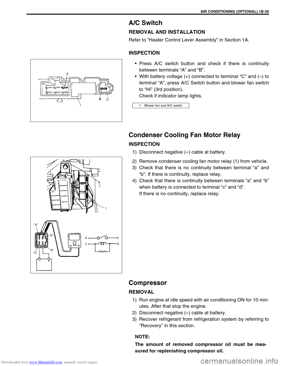
Press A/C switch button and check if there is continuity
between terminals “A” and “B”.
With battery voltage (+) connected to terminal “C” and (–) to
terminal “A”, press A/C Switch button and blower fan switch
to “Hi” (3rd position).
Check if indicator lamp lights.
Condenser Cooling Fan Motor Relay
INSPECTION
1) Disconnect negative (–) cable at battery.
2) Remove condenser cooling fan motor relay (1) from vehicle.
3) Check that there is no continuity between terminal “a” and
“b”. If there is continuity, replace relay.
4) Check that there is continuity between terminals “a” and “b”
when battery is connected to terminal “c” and “d”.
If there is no continuity, replace relay.
Compressor
REMOVAL
1) Run engine at idle speed with air conditioning ON for 10 min-
utes. After that stop the engine.
2) Disconnect negative (–) cable at battery.
3) Recover refrigerant from refrigeration system by referring to
“Recovery” in this section.
1. Blower fan and A/C switch
NOTE:
The amount of removed compressor oil must be mea-
sured for replenishing compressor oil.
Page 268 of 687

Downloaded from www.Manualslib.com manuals search engine BRAKES 5-7
Brake warning light
turns on when brake
is appliedBrake fluid leaking from brake line Investigate leaky point, correct it
and add brake fluid.
Insufficient amount of brake fluid Add brake fluid.
Faulty P & Differential valve (Differential switch) Replace.
Brake warning light
fails to turn on even
when parking brake is
appliedBulb burnt out Replace bulb.
Brake warning light circuit open Repair circuit.
ABS warning light
does not turn on for 2
sec. after ignition
switch has turned ON.Bulb burnt out Replace bulb.
ABS warning light circuit open, if equipped with
ABS (including check relay)Check system referring to “TABLE-
A” in Section 5E.
ABS warning light
remains on after igni-
tion switch has turned
on for 2 sec.Malfunctioning ABS, if equipped with ABS Check system referring to “TABLE-
B” in Section 5E. Condition Possible Cause Correction
Page 361 of 687

Downloaded from www.Manualslib.com manuals search engine 6-4 ENGINE GENERAL INFORMATION AND DIAGNOSIS
Precaution on fuel system service
Work must be done with no smoking, in a well-ventilated
area and away from any open flames.
As fuel feed line (between fuel pump and fuel delivery pipe)
is still under high fuel pressure even after engine was
stopped, loosening or disconnecting fuel feed line directly
may cause dangerous spout of fuel to occur where loosened
or disconnected.
Before loosening or disconnecting fuel feed line, make sure
to release fuel pressure according to “FUEL PRESSURE
RELIEF PROCEDURE”. A small amount of fuel may be
released after the fuel line is disconnected. In order to
reduce the chance of personal injury, cover the fitting to be
disconnected with a shop cloth. Put that cloth in an approved
container when disconnection is completed.
Never run engine with fuel pump relay disconnected when
engine and exhaust system are hot.
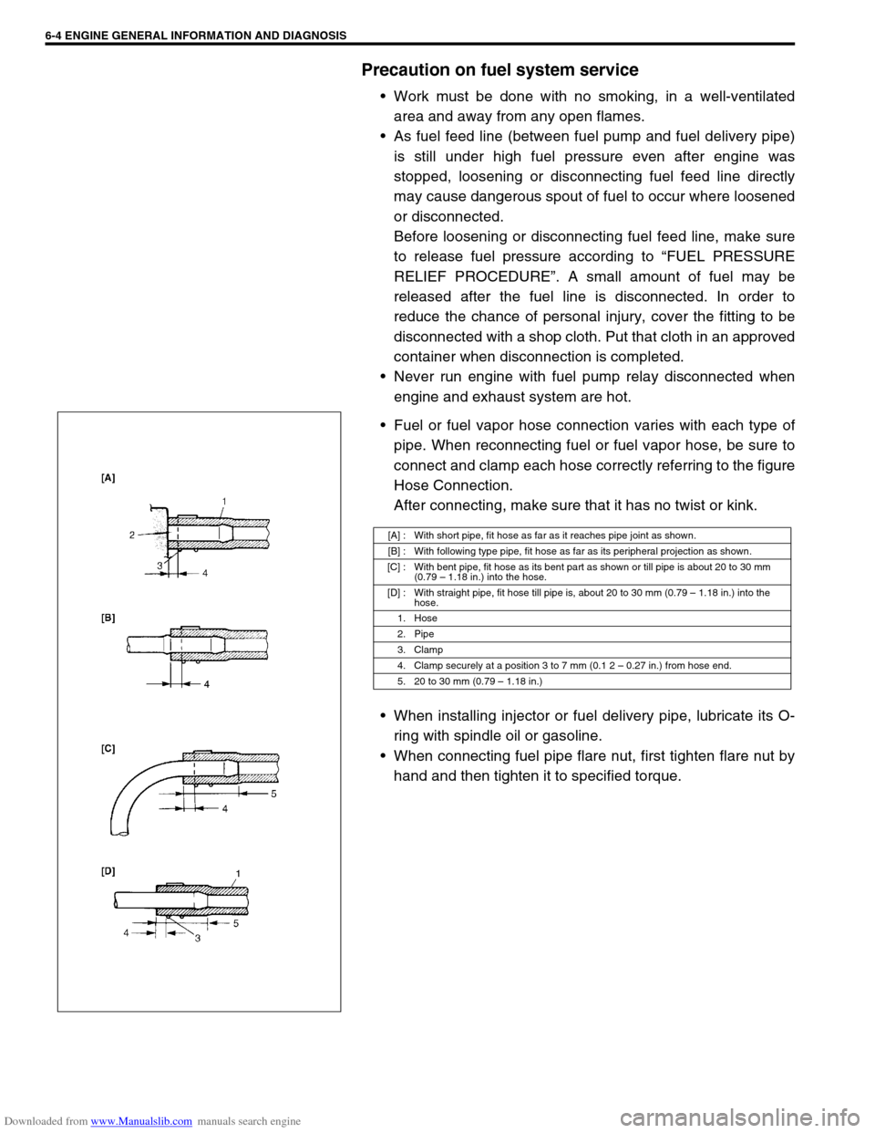
Fuel or fuel vapor hose connection varies with each type of
pipe. When reconnecting fuel or fuel vapor hose, be sure to
connect and clamp each hose correctly referring to the figure
Hose Connection.
After connecting, make sure that it has no twist or kink.
When installing injector or fuel delivery pipe, lubricate its O-
ring with spindle oil or gasoline.
When connecting fuel pipe flare nut, first tighten flare nut by
hand and then tighten it to specified torque.
[A] : With short pipe, fit hose as far as it reaches pipe joint as shown.
[B] : With following type pipe, fit hose as far as its peripheral projection as shown.
[C] : With bent pipe, fit hose as its bent part as shown or till pipe is about 20 to 30 mm
(0.79 – 1.18 in.) into the hose.
[D] : With straight pipe, fit hose till pipe is, about 20 to 30 mm (0.79 – 1.18 in.) into the
hose.
1. Hose
2. Pipe
3. Clamp
4. Clamp securely at a position 3 to 7 mm (0.1 2 – 0.27 in.) from hose end.
5. 20 to 30 mm (0.79 – 1.18 in.)