Switch SUZUKI JIMNY 2005 3.G Service Workshop Manual
[x] Cancel search | Manufacturer: SUZUKI, Model Year: 2005, Model line: JIMNY, Model: SUZUKI JIMNY 2005 3.GPages: 687, PDF Size: 13.38 MB
Page 630 of 687
Downloaded from www.Manualslib.com manuals search engine ENGINE AND EMISSION CONTROL SYSTEM 6E-25
INSTALLATION
For installation, reverse removal procedure and note following
precautions.
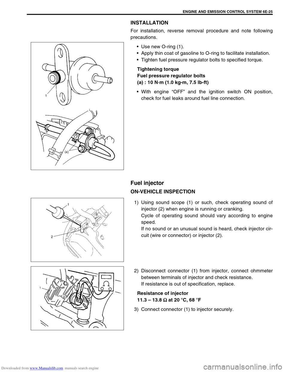
Use new O-ring (1).
Apply thin coat of gasoline to O-ring to facilitate installation.
Tighten fuel pressure regulator bolts to specified torque.
Tightening torque
Fuel pressure regulator bolts
(a) : 10 N·m (1.0 kg-m, 7.5 lb-ft)
With engine “OFF” and the ignition switch ON position,
check for fuel leaks around fuel line connection.
Fuel injector
ON-VEHICLE INSPECTION
1) Using sound scope (1) or such, check operating sound of
injector (2) when engine is running or cranking.
Cycle of operating sound should vary according to engine
speed.
If no sound or an unusual sound is heard, check injector cir-
cuit (wire or connector) or injector (2).
2) Disconnect connector (1) from injector, connect ohmmeter
between terminals of injector and check resistance.
If resistance is out of specification, replace.
Resistance of injector
11.3 – 13.8
Ω
ΩΩ Ω at 20 °C, 68 °F
3) Connect connector (1) to injector securely.
Page 632 of 687
Downloaded from www.Manualslib.com manuals search engine ENGINE AND EMISSION CONTROL SYSTEM 6E-27
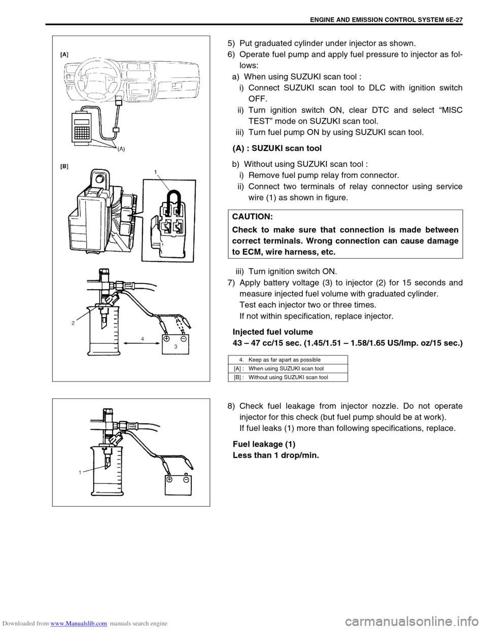
5) Put graduated cylinder under injector as shown.
6) Operate fuel pump and apply fuel pressure to injector as fol-
lows:
a) When using SUZUKI scan tool :
i) Connect SUZUKI scan tool to DLC with ignition switch
OFF.
ii) Turn ignition switch ON, clear DTC and select “MISC
TEST” mode on SUZUKI scan tool.
iii) Turn fuel pump ON by using SUZUKI scan tool.
(A) : SUZUKI scan tool
b) Without using SUZUKI scan tool :
i) Remove fuel pump relay from connector.
ii) Connect two terminals of relay connector using service
wire (1) as shown in figure.
iii) Turn ignition switch ON.
7) Apply battery voltage (3) to injector (2) for 15 seconds and
measure injected fuel volume with graduated cylinder.
Test each injector two or three times.
If not within specification, replace injector.
Injected fuel volume
43 – 47 cc/15 sec. (1.45/1.51 – 1.58/1.65 US/Imp. oz/15 sec.)
8) Check fuel leakage from injector nozzle. Do not operate
injector for this check (but fuel pump should be at work).
If fuel leaks (1) more than following specifications, replace.
Fuel leakage (1)
Less than 1 drop/min. CAUTION:
Check to make sure that connection is made between
correct terminals. Wrong connection can cause damage
to ECM, wire harness, etc.
4. Keep as far apart as possible
[A] : When using SUZUKI scan tool
[B] : Without using SUZUKI scan tool
Page 633 of 687
Downloaded from www.Manualslib.com manuals search engine 6E-28 ENGINE AND EMISSION CONTROL SYSTEM
INSTALLATION
For installation, reverse removal procedure and note following
precautions.
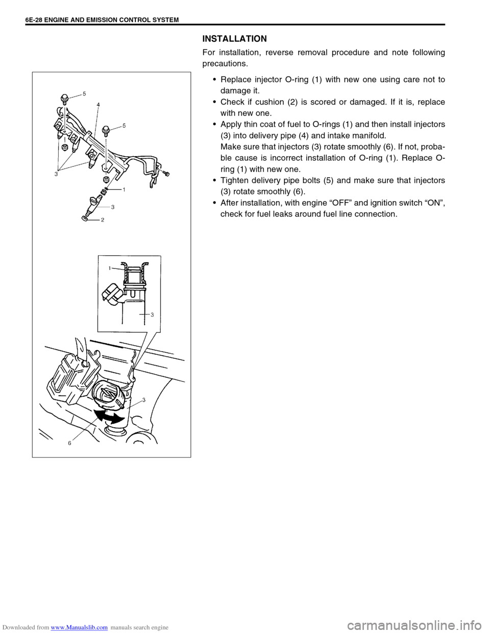
Replace injector O-ring (1) with new one using care not to
damage it.
Check if cushion (2) is scored or damaged. If it is, replace
with new one.
Apply thin coat of fuel to O-rings (1) and then install injectors
(3) into delivery pipe (4) and intake manifold.
Make sure that injectors (3) rotate smoothly (6). If not, proba-
ble cause is incorrect installation of O-ring (1). Replace O-
ring (1) with new one.
Tighten delivery pipe bolts (5) and make sure that injectors
(3) rotate smoothly (6).
After installation, with engine “OFF” and ignition switch “ON”,
check for fuel leaks around fuel line connection.
Page 642 of 687
Downloaded from www.Manualslib.com manuals search engine ENGINE AND EMISSION CONTROL SYSTEM 6E-37
Fuel cut operation
INSPECTION
1) Warm up engine to normal operating temperature.
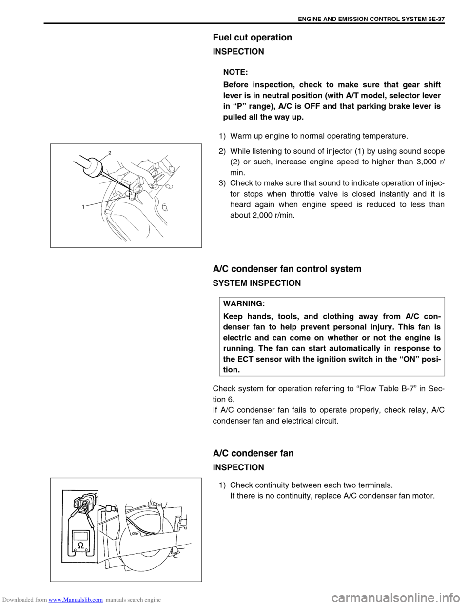
2) While listening to sound of injector (1) by using sound scope
(2) or such, increase engine speed to higher than 3,000 r/
min.
3) Check to make sure that sound to indicate operation of injec-
tor stops when throttle valve is closed instantly and it is
heard again when engine speed is reduced to less than
about 2,000 r/min.
A/C condenser fan control system
SYSTEM INSPECTION
Check system for operation referring to “Flow Table B-7” in Sec-
tion 6.
If A/C condenser fan fails to operate properly, check relay, A/C
condenser fan and electrical circuit.
A/C condenser fan
INSPECTION
1) Check continuity between each two terminals.
If there is no continuity, replace A/C condenser fan motor. NOTE:
Before inspection, check to make sure that gear shift
lever is in neutral position (with A/T model, selector lever
in “P” range), A/C is OFF and that parking brake lever is
pulled all the way up.
WARNING:
Keep hands, tools, and clothing away from A/C con-
denser fan to help prevent personal injury. This fan is
electric and can come on whether or not the engine is
running. The fan can start automatically in response to
the ECT sensor with the ignition switch in the “ON” posi-
tion.
Page 643 of 687
Downloaded from www.Manualslib.com manuals search engine 6E-38 ENGINE AND EMISSION CONTROL SYSTEM
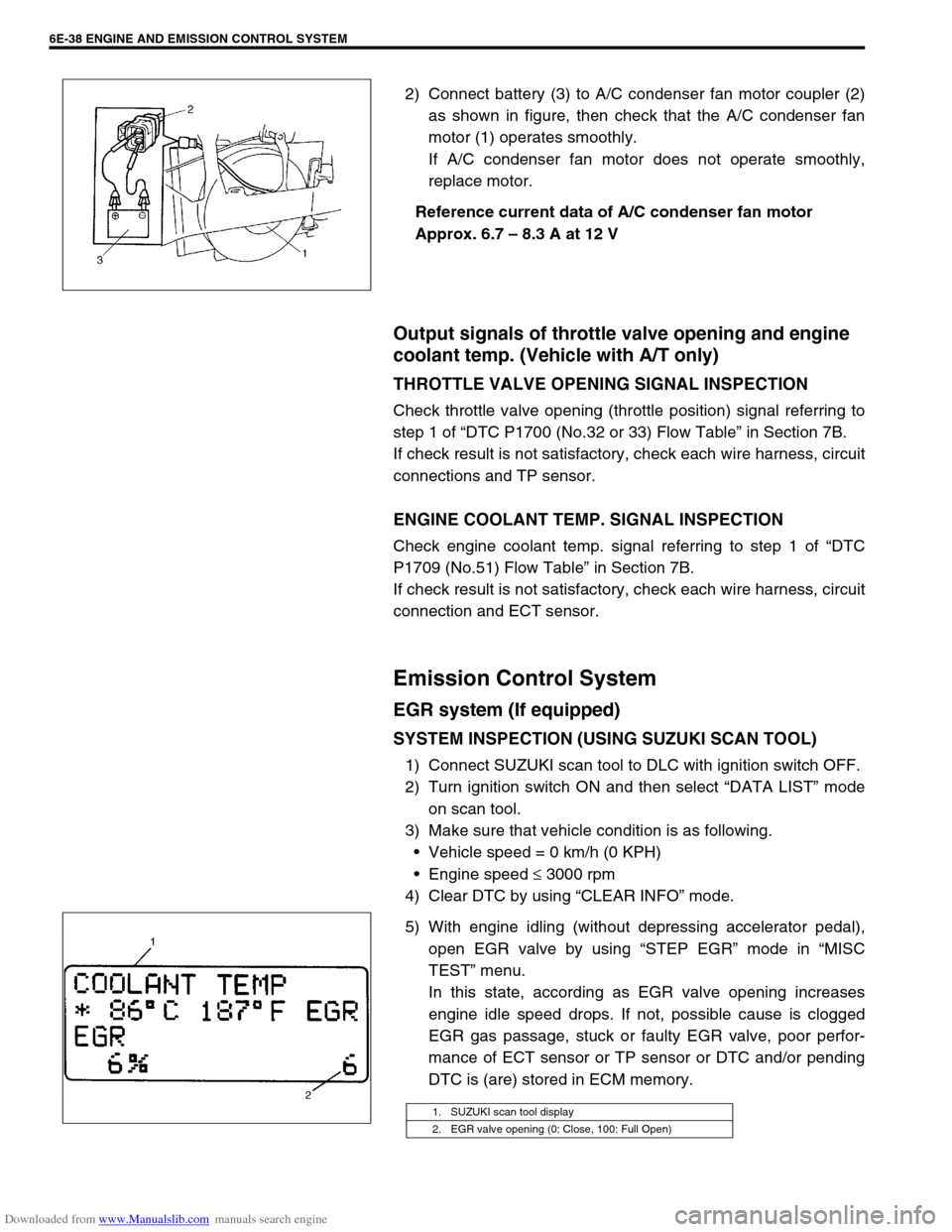
2) Connect battery (3) to A/C condenser fan motor coupler (2)
as shown in figure, then check that the A/C condenser fan
motor (1) operates smoothly.
If A/C condenser fan motor does not operate smoothly,
replace motor.
Reference current data of A/C condenser fan motor
Approx. 6.7 – 8.3 A at 12 V
Output signals of throttle valve opening and engine
coolant temp. (Vehicle with A/T only)
THROTTLE VALVE OPENING SIGNAL INSPECTION
Check throttle valve opening (throttle position) signal referring to
step 1 of “DTC P1700 (No.32 or 33) Flow Table” in Section 7B.
If check result is not satisfactory, check each wire harness, circuit
connections and TP sensor.
ENGINE COOLANT TEMP. SIGNAL INSPECTION
Check engine coolant temp. signal referring to step 1 of “DTC
P1709 (No.51) Flow Table” in Section 7B.
If check result is not satisfactory, check each wire harness, circuit
connection and ECT sensor.
Emission Control System
EGR system (If equipped)
SYSTEM INSPECTION (USING SUZUKI SCAN TOOL)
1) Connect SUZUKI scan tool to DLC with ignition switch OFF.
2) Turn ignition switch ON and then select “DATA LIST” mode
on scan tool.
3) Make sure that vehicle condition is as following.
Vehicle speed = 0 km/h (0 KPH)
Engine speed ≤ 3000 rpm
4) Clear DTC by using “CLEAR INFO” mode.
5) With engine idling (without depressing accelerator pedal),
open EGR valve by using “STEP EGR” mode in “MISC
TEST” menu.
In this state, according as EGR valve opening increases
engine idle speed drops. If not, possible cause is clogged
EGR gas passage, stuck or faulty EGR valve, poor perfor-
mance of ECT sensor or TP sensor or DTC and/or pending
DTC is (are) stored in ECM memory.
1. SUZUKI scan tool display
2. EGR valve opening (0: Close, 100: Full Open)
Page 645 of 687
Downloaded from www.Manualslib.com manuals search engine 6E-40 ENGINE AND EMISSION CONTROL SYSTEM
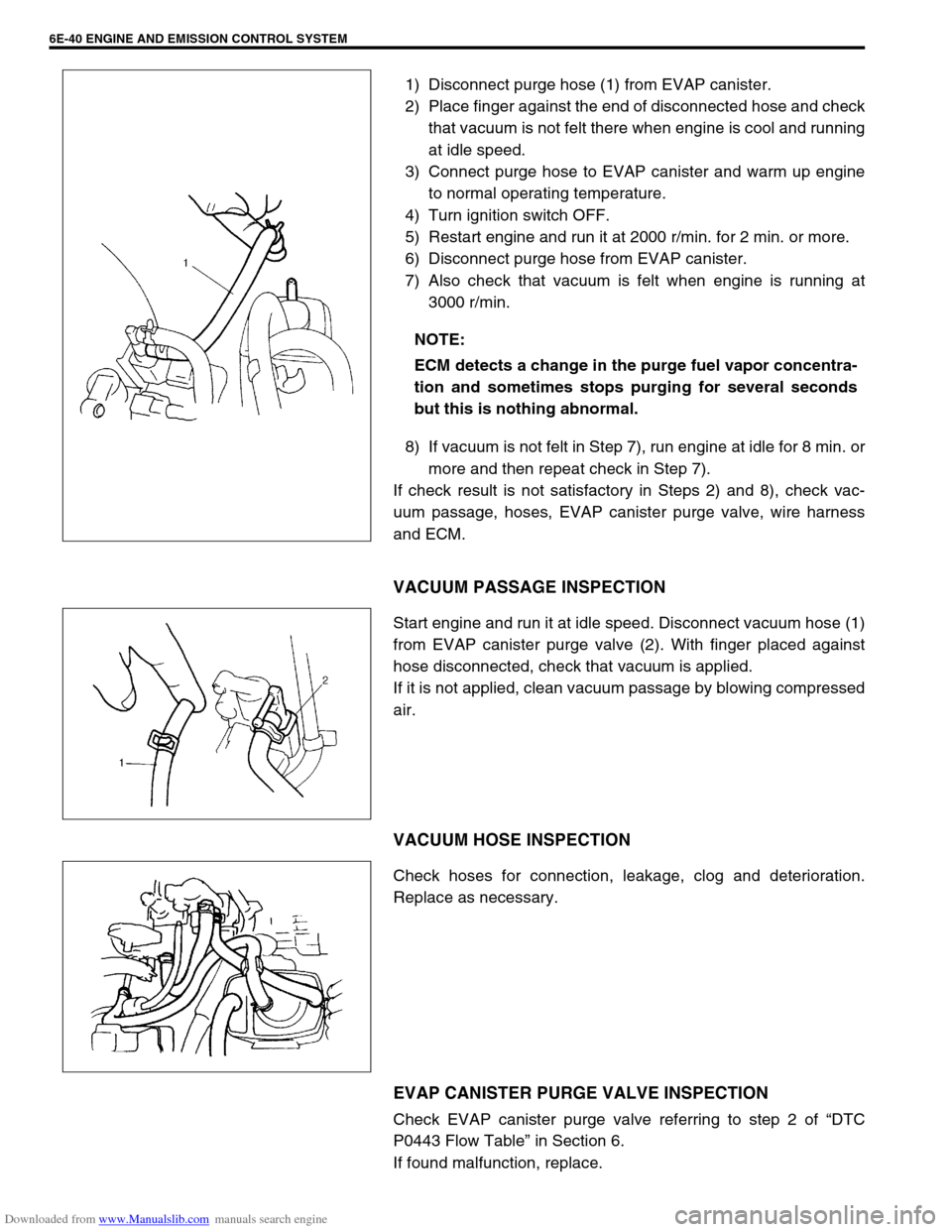
1) Disconnect purge hose (1) from EVAP canister.
2) Place finger against the end of disconnected hose and check
that vacuum is not felt there when engine is cool and running
at idle speed.
3) Connect purge hose to EVAP canister and warm up engine
to normal operating temperature.
4) Turn ignition switch OFF.
5) Restart engine and run it at 2000 r/min. for 2 min. or more.
6) Disconnect purge hose from EVAP canister.
7) Also check that vacuum is felt when engine is running at
3000 r/min.
8) If vacuum is not felt in Step 7), run engine at idle for 8 min. or
more and then repeat check in Step 7).
If check result is not satisfactory in Steps 2) and 8), check vac-
uum passage, hoses, EVAP canister purge valve, wire harness
and ECM.
VACUUM PASSAGE INSPECTION
Start engine and run it at idle speed. Disconnect vacuum hose (1)
from EVAP canister purge valve (2). With finger placed against
hose disconnected, check that vacuum is applied.
If it is not applied, clean vacuum passage by blowing compressed
air.
VACUUM HOSE INSPECTION
Check hoses for connection, leakage, clog and deterioration.
Replace as necessary.
EVAP CANISTER PURGE VALVE INSPECTION
Check EVAP canister purge valve referring to step 2 of “DTC
P0443 Flow Table” in Section 6.
If found malfunction, replace.NOTE:
ECM detects a change in the purge fuel vapor concentra-
tion and sometimes stops purging for several seconds
but this is nothing abnormal.
Page 650 of 687

Downloaded from www.Manualslib.com manuals search engine IGNITION SYSTEM (ELECTRONIC IGNITION SYSTEM) 6F-1
6G
6F2
6G
6H
7D
7E
7F
7A1
7A1
7D
7E
7F
8A
8B
8C
8D
8E
6K
6F
7A
10
10A
10B
SECTION 6F
IGNITION SYSTEM
(ELECTRONIC IGNITION SYSTEM)
CONTENTS
General Description ........................................ 6F-2
Diagnosis ......................................................... 6F-3
On-Vehicle Service.......................................... 6F-5
Ignition Spark Test ........................................ 6F-5
High-tension Cords ....................................... 6F-5
Spark Plugs ................................................... 6F-6Ignition Coil Assembly (Including Ignitor) ...... 6F-7
Crankshaft Position Sensor (CKP Sensor) ... 6F-8
Ignition Timing............................................... 6F-8
Special Tools ................................................. 6F-10
Tightening Torque Specification ................. 6F-10
WARNING:
For vehicles equipped with Supplemental Restraint (Air Bag) System:
Service on and around the air bag system components or wiring must be performed only by an
authorized SUZUKI dealer. Refer to “Air Bag System Components and Wiring Location View” under
“General Description” in air bag system section in order to confirm whether you are performing ser-
vice on or near the air bag system components or wiring. Please observe all WARNINGS and “Ser-
vice Precautions” under “On-Vehicle Service” in air bag system section before performing service
on or around the air bag system components or wiring. Failure to follow WARNINGS could result in
unintentional activation of the system or could render the system inoperative. Either of these two
conditions may result in severe injury.
Technical service work must be started at least 90 seconds after the ignition switch is turned to the
“LOCK” position and the negative cable is disconnected from the battery. Otherwise, the system
may be activated by reserve energy in the Sensing and Diagnostic Module (SDM).
Page 651 of 687
Downloaded from www.Manualslib.com manuals search engine 6F-2 IGNITION SYSTEM (ELECTRONIC IGNITION SYSTEM)
General Description
The ignition system is an electronic (distributorless) ignition system. It consists of the parts as described below
and has an electronic ignition control system.
ECM
It detects the engine and vehicle conditions through the signals from the sensors, determines the most suit-
able ignition timing and time for electricity to flow to the primary coil and sends a signal to the ignitor (power
unit) in the ignition coil assembly.
Ignition coil assembly (including an ignitor)
The ignition coil assembly has a built-in ignitor which turns ON and OFF the current flow to the primary coil
according to the signal from ECM. When the current flow to the primary coil is turned OFF, a high voltage is
induced in the secondary coil.
High tension cords and spark plugs.
CMP sensor (Camshaft position sensor) and CKP sensor (Crankshaft position sensor)
Using signals from these sensors, ECM identifies the specific cylinder whose piston is in the compression
stroke, detects the crank angle and adjust initial ignition timing automatically.
TP sensor, ECT sensor, MAP sensor and other sensors/switches
Refer to “Electronic Control System” in Section 6E for details.
Although this ignition system does not have a distributor, it has two ignition coil assemblies (one is for No.1 and
No.4 spark plugs and the other is for No.2 and No.3 spark plugs). When an ignition signal is sent from ECM to
the ignitor in the ignition coil assembly for No.1 and No.4 spark plugs, a high voltage is induced in the secondary
coil and that passes through the high-tension cords and causes No.1 and No.4 spark plugs to spark simulta-
neously. Likewise, when an ignition signal is sent to the ignitor in the other ignition coil assembly, No.2 and No.3
spark plugs spark simultaneously.
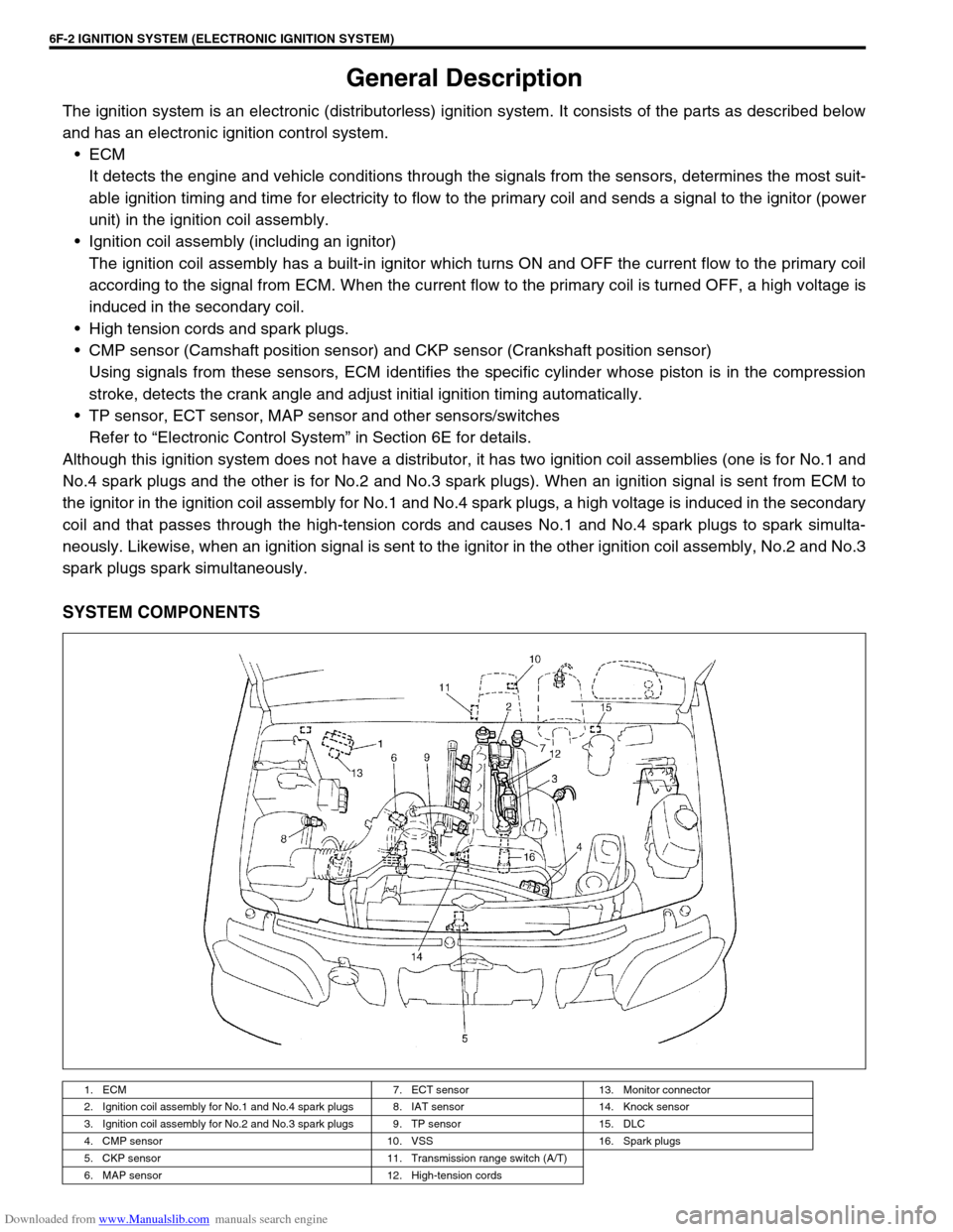
SYSTEM COMPONENTS
1. ECM 7. ECT sensor 13. Monitor connector
2. Ignition coil assembly for No.1 and No.4 spark plugs 8. IAT sensor 14. Knock sensor
3. Ignition coil assembly for No.2 and No.3 spark plugs 9. TP sensor 15. DLC
4. CMP sensor 10. VSS 16. Spark plugs
5. CKP sensor 11. Transmission range switch (A/T)
6. MAP sensor 12. High-tension cords
Page 652 of 687
Downloaded from www.Manualslib.com manuals search engine IGNITION SYSTEM (ELECTRONIC IGNITION SYSTEM 6F-3
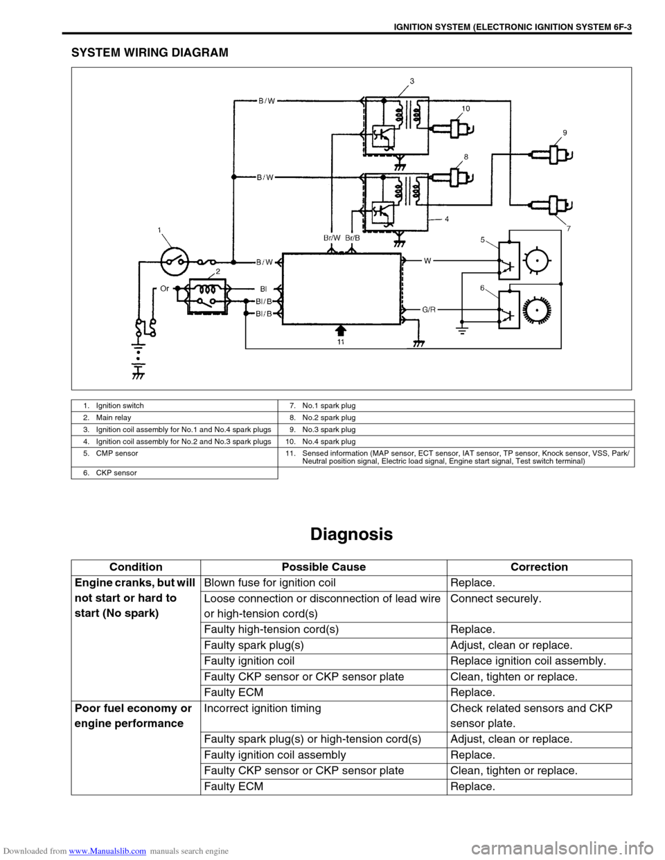
SYSTEM WIRING DIAGRAM
Diagnosis
1. Ignition switch 7. No.1 spark plug
2. Main relay 8. No.2 spark plug
3. Ignition coil assembly for No.1 and No.4 spark plugs 9. No.3 spark plug
4. Ignition coil assembly for No.2 and No.3 spark plugs 10. No.4 spark plug
5. CMP sensor 11. Sensed information (MAP sensor, ECT sensor, IAT sensor, TP sensor, Knock sensor, VSS, Park/
Neutral position signal, Electric load signal, Engine start signal, Test switch terminal)
6. CKP sensor
Condition Possible Cause Correction
Engine cranks, but will
not start or hard to
start (No spark)Blown fuse for ignition coil Replace.
Loose connection or disconnection of lead wire
or high-tension cord(s)Connect securely.
Faulty high-tension cord(s) Replace.
Faulty spark plug(s) Adjust, clean or replace.
Faulty ignition coil Replace ignition coil assembly.
Faulty CKP sensor or CKP sensor plate Clean, tighten or replace.
Faulty ECM Replace.
Poor fuel economy or
engine performanceIncorrect ignition timing Check related sensors and CKP
sensor plate.
Faulty spark plug(s) or high-tension cord(s) Adjust, clean or replace.
Faulty ignition coil assembly Replace.
Faulty CKP sensor or CKP sensor plate Clean, tighten or replace.
Faulty ECM Replace.
Page 657 of 687
Downloaded from www.Manualslib.com manuals search engine 6F-8 IGNITION SYSTEM (ELECTRONIC IGNITION SYSTEM)
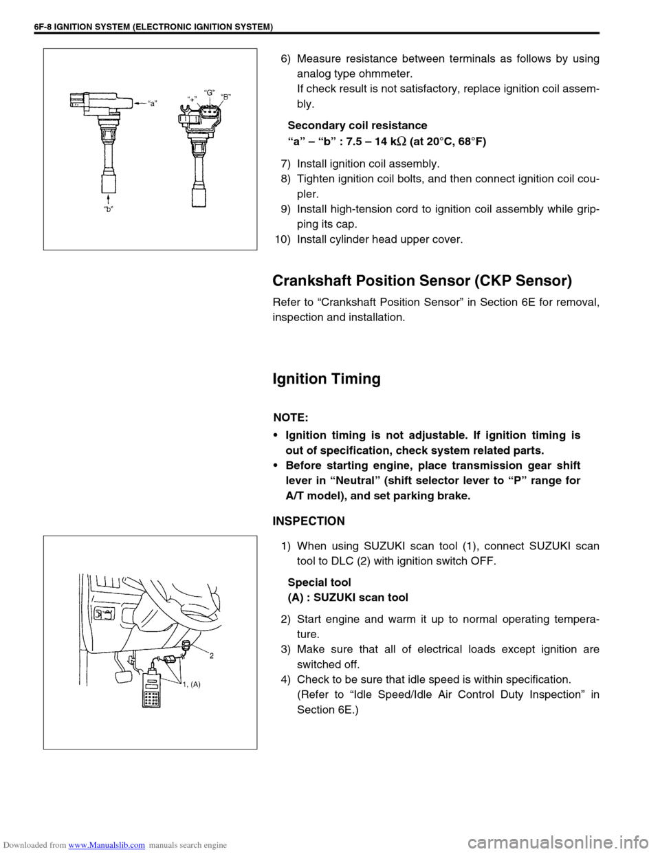
6) Measure resistance between terminals as follows by using
analog type ohmmeter.
If check result is not satisfactory, replace ignition coil assem-
bly.
Secondary coil resistance
“a” – “b” : 7.5 – 14 k
Ω (at 20°C, 68°F)
7) Install ignition coil assembly.
8) Tighten ignition coil bolts, and then connect ignition coil cou-
pler.
9) Install high-tension cord to ignition coil assembly while grip-
ping its cap.
10) Install cylinder head upper cover.
Crankshaft Position Sensor (CKP Sensor)
Refer to “Crankshaft Position Sensor” in Section 6E for removal,
inspection and installation.
Ignition Timing
INSPECTION
1) When using SUZUKI scan tool (1), connect SUZUKI scan
tool to DLC (2) with ignition switch OFF.
Special tool
(A) : SUZUKI scan tool
2) Start engine and warm it up to normal operating tempera-
ture.
3) Make sure that all of electrical loads except ignition are
switched off.
4) Check to be sure that idle speed is within specification.
(Refer to “Idle Speed/Idle Air Control Duty Inspection” in
Section 6E.)
NOTE:
Ignition timing is not adjustable. If ignition timing is
out of specification, check system related parts.
Before starting engine, place transmission gear shift
lever in “Neutral” (shift selector lever to “P” range for
A/T model), and set parking brake.