ECO mode SUZUKI JIMNY 2005 3.G Service Workshop Manual
[x] Cancel search | Manufacturer: SUZUKI, Model Year: 2005, Model line: JIMNY, Model: SUZUKI JIMNY 2005 3.GPages: 687, PDF Size: 13.38 MB
Page 2 of 687

Downloaded from www.Manualslib.com manuals search engine FOREWORD
This manual contains procedures for diagnosis, maintenance, adjustments, minor service operations, replace-
ment of components (Service) and for disassembly and assembly of major components (Unit Repair-Overhaul).
Applicable model: JIMNY (SN413) of and after the vehicle identification numbers below.
The contents are classified into sections each of which is given a section number as indicated in the Table of
Contents on following page. And on the first page of each individual section is an index of that section.
This manual should be kept in a handy place for ready reference of the service work.
Strict observance of the so specified items will enable one to obtain the full performance of the vehicle.
When replacing parts or servicing by disassembling, it is recommended to use SUZUKI genuine parts, tools and
service materials (lubricant, sealants, etc.) as specified in each description.
All information, illustrations and specifications contained in this literature are based on the latest product infor-
mation available at the time of publication approval. And used as the main subject of description is the vehicle of
standard specifications among others.
Therefore, note that illustrations may differ from the vehicle being actually serviced.
The right is reserved to make changes at any time without notice.
Related Manual
© COPYRIGHT SUZUKI MOTOR CORPORATION 2002JSAFJA43V00140001
JSAFJB43V00140001
JSAFJB43V20140001
JSAFJB43V24140001
JSAFJB43V34140001
JS3JB43V 24140001
JS3JB43V 34140001
Manual Name Manual No.
JIMNY (SN413) WIRING DIAGRAM MANUAL 99512-81A20-015
Page 178 of 687

Downloaded from www.Manualslib.com manuals search engine FRONT SUSPENSION 3D-5
Components and Functions
Component Function
4WD switch When the transfer shift lever is shifted to 4L or 4H position from 2H, this switch
turns ON and cause the 4WD control system to turn ON.
4WD controller When the 4WD switch turns on, the 4WD controller activates VSV2 to lock the
air locking hubs and when it receives an “ON” signal from the vacuum switch, it
makes VSV2 to complete operation within 5 seconds and causes the 4WD indi-
cator light to light up.
If vacuum in the vacuum circuit fails to reach the specified level due to a leakage
in the vacuum circuit (when no “ON” signal is inputted from the vacuum switch),
the 4WD controller stops operation of VSV2 in 15 seconds and makes the 4WD
indicator light to flash to warn occurrence of a trouble.
When the 4WD switch turns off, the 4WD controller activates VSV1 for 10 sec-
onds to unlock the hubs and at the same time makes the 4WD indicator light
turn off.
VSV1 VSV1 operates according to the signal from the 4WD controller. When it is acti-
vated, the port opens and vacuum in the intake manifold is applied through the
vacuum circuit to unlock to the slide gear in the air locking hub. As a result, the
air locking hubs are unlocked.
VSV2 VSV2 operates according to the signal from the 4WD controller. When it is acti-
vated, the port opens and vacuum in the intake manifold is applied through the
vacuum circuit to lock to the slide gear in the air locking hub. As a result, the air
locking hubs are locked.
Vacuum switch When VSV2 receives the “ON” signal from 4WD switch, vacuum is applied
through its circuit to the vacuum switch. The vacuum switch turns on when it
detects vacuum exceeding 260 mmHg.
“4WD” indicator lamp It lights up when 4WD control system is in the 4WD mode.
It flashes to warn that locking hub operation has not completed (4WD control
system fails to shift 4WD).
Page 246 of 687

Downloaded from www.Manualslib.com manuals search engine WHEELS AND TIRES 3F-3
Replacement Wheels
Wheels must be replaced if they are bent, dented, have excessive
lateral or radial runout, leak air through welds, have elongated
bolt holes, if lug nuts won’t stay tight, or if they are heavily rusted.
Wheels with greater runout than shown in “How to Measure
Wheel Runout” may cause objectional vibrations.
Wheels for replacement must be equivalent to the originally
equipped wheels in load capacity, diameter, rim width, off-set and
mounting configuration. A wheel of improper size or type may
affect wheel and bearing life, brake cooling, speedometer / odom-
eter calibration, ground clearance to the body and chassis.
How To Measure Wheel Runout
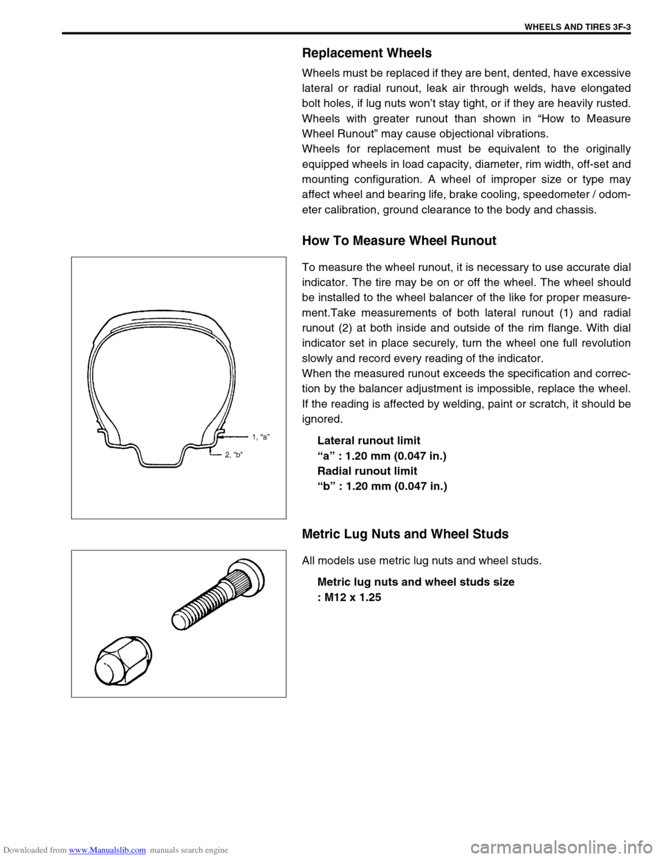
To measure the wheel runout, it is necessary to use accurate dial
indicator. The tire may be on or off the wheel. The wheel should
be installed to the wheel balancer of the like for proper measure-
ment.Take measurements of both lateral runout (1) and radial
runout (2) at both inside and outside of the rim flange. With dial
indicator set in place securely, turn the wheel one full revolution
slowly and record every reading of the indicator.
When the measured runout exceeds the specification and correc-
tion by the balancer adjustment is impossible, replace the wheel.
If the reading is affected by welding, paint or scratch, it should be
ignored.
Lateral runout limit
“a” : 1.20 mm (0.047 in.)
Radial runout limit
“b” : 1.20 mm (0.047 in.)
Metric Lug Nuts and Wheel Studs
All models use metric lug nuts and wheel studs.
Metric lug nuts and wheel studs size
: M12 x 1.25
Page 249 of 687

Downloaded from www.Manualslib.com manuals search engine 3F-6 WHEELS AND TIRES
Maintenance and Minor Adjustments
Wheel and Tire
Wheel repairs that use welding, heating, or peening are not approved. All damaged wheels should be replaced.
Studs
If a broken stud is found, see Section 3E (rear) or Section 3D (front) for Note and Replacement procedure.
Matched tires and wheels
(For vehicle equipped with steel wheels)
Tires and wheels are matchmounted at the assembly plant.
This means that the radially stiffest part of the tire, or “high spot”,
is matched to the smallest radius or “low spot” of the wheel.
This is done to provide the smoothest possible ride.
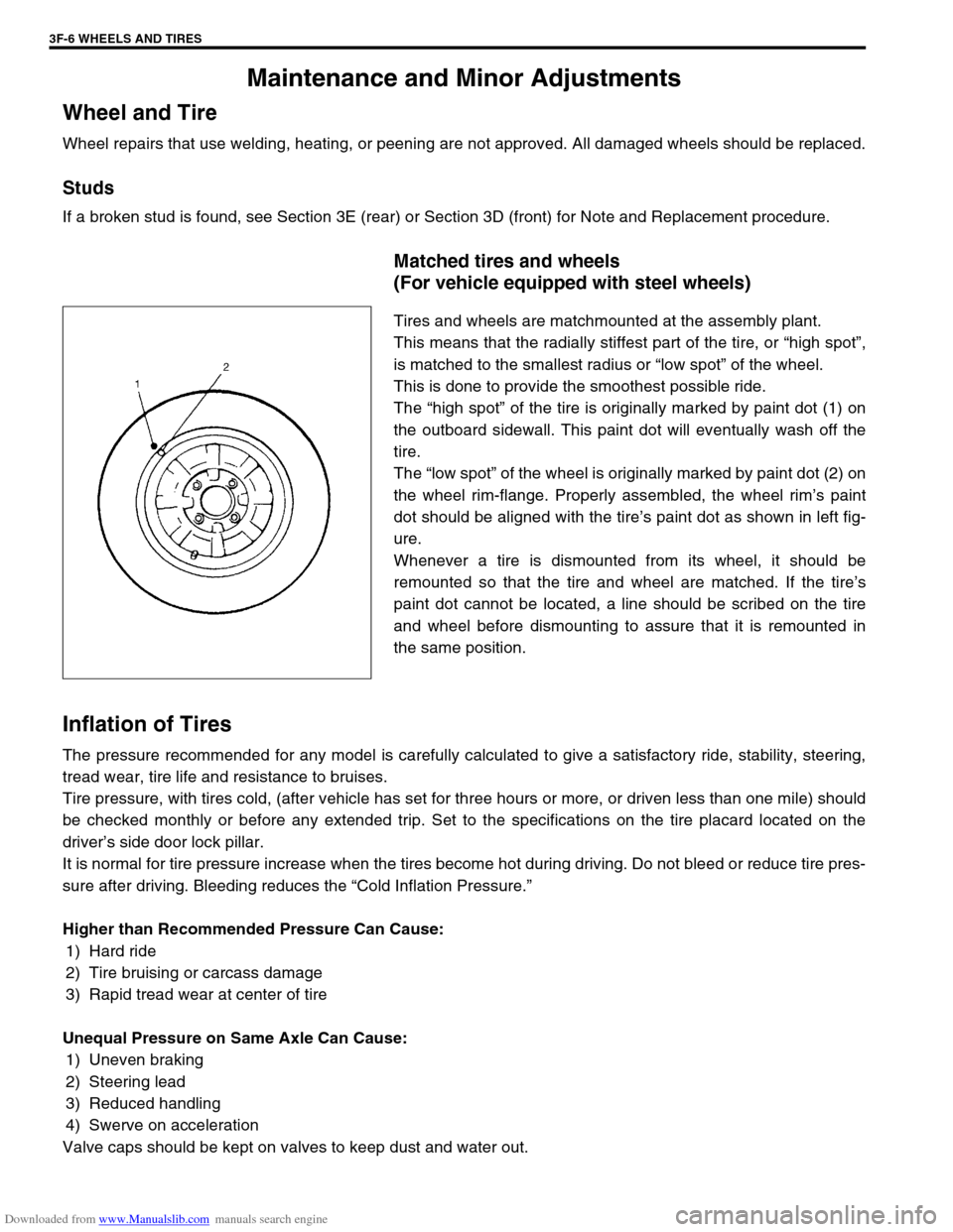
The “high spot” of the tire is originally marked by paint dot (1) on
the outboard sidewall. This paint dot will eventually wash off the
tire.
The “low spot” of the wheel is originally marked by paint dot (2) on
the wheel rim-flange. Properly assembled, the wheel rim’s paint
dot should be aligned with the tire’s paint dot as shown in left fig-
ure.
Whenever a tire is dismounted from its wheel, it should be
remounted so that the tire and wheel are matched. If the tire’s
paint dot cannot be located, a line should be scribed on the tire
and wheel before dismounting to assure that it is remounted in
the same position.
Inflation of Tires
The pressure recommended for any model is carefully calculated to give a satisfactory ride, stability, steering,
tread wear, tire life and resistance to bruises.
Tire pressure, with tires cold, (after vehicle has set for three hours or more, or driven less than one mile) should
be checked monthly or before any extended trip. Set to the specifications on the tire placard located on the
driver’s side door lock pillar.
It is normal for tire pressure increase when the tires become hot during driving. Do not bleed or reduce tire pres-
sure after driving. Bleeding reduces the “Cold Inflation Pressure.”
Higher than Recommended Pressure Can Cause:
1) Hard ride
2) Tire bruising or carcass damage
3) Rapid tread wear at center of tire
Unequal Pressure on Same Axle Can Cause:
1) Uneven braking
2) Steering lead
3) Reduced handling
4) Swerve on acceleration
Valve caps should be kept on valves to keep dust and water out.
Page 362 of 687

Downloaded from www.Manualslib.com manuals search engine ENGINE GENERAL INFORMATION AND DIAGNOSIS 6-5
Fuel pressure relief procedure
After making sure that engine is cold, release fuel pressure as fol-
lows.
1) Place transmission gear shift lever in “Neutral” (Shift selector
lever to “P” range for A/T model), set parking brake, and
block drive wheels.
2) Remove relay box cover.
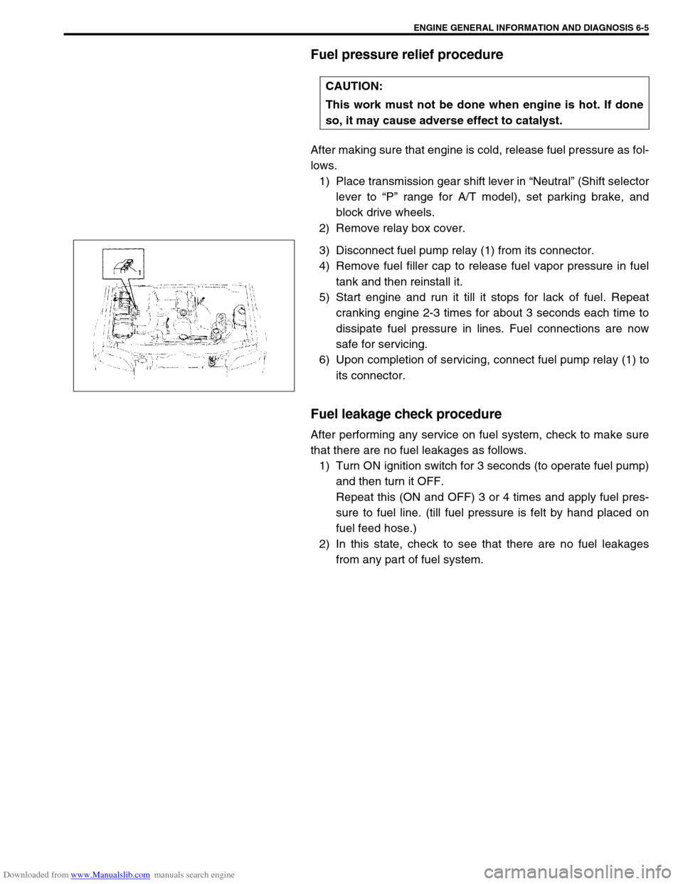
3) Disconnect fuel pump relay (1) from its connector.
4) Remove fuel filler cap to release fuel vapor pressure in fuel
tank and then reinstall it.
5) Start engine and run it till it stops for lack of fuel. Repeat
cranking engine 2-3 times for about 3 seconds each time to
dissipate fuel pressure in lines. Fuel connections are now
safe for servicing.
6) Upon completion of servicing, connect fuel pump relay (1) to
its connector.
Fuel leakage check procedure
After performing any service on fuel system, check to make sure
that there are no fuel leakages as follows.
1) Turn ON ignition switch for 3 seconds (to operate fuel pump)
and then turn it OFF.
Repeat this (ON and OFF) 3 or 4 times and apply fuel pres-
sure to fuel line. (till fuel pressure is felt by hand placed on
fuel feed hose.)
2) In this state, check to see that there are no fuel leakages
from any part of fuel system. CAUTION:
This work must not be done when engine is hot. If done
so, it may cause adverse effect to catalyst.
Page 376 of 687

Downloaded from www.Manualslib.com manuals search engine ENGINE GENERAL INFORMATION AND DIAGNOSIS 6-19
Fail-safe table
When any of the following DTCs is detected, ECM enters fail-safe mode as long as malfunction continues to
exist but that mode is canceled when ECM detects normal condition after that.
DTC NO. DETECTED ITEM FAIL-SAFE OPERATION (SYMPTOM)
P0105
(No.11)Manifold absolute pressure sensor circuit
malfunctionECM uses value determined by throttle opening and
engine speed.
P0110
(No.18)Intake air temp. sensor circuit malfunctionECM controls actuators assuming that intake air tem-
perature is 20 °C (68 °F).
P0115
(No.19)Engine coolant temp. sensor circuit mal-
functionECM controls actuators assuming that engine coolant
temperature is 80 °C (176 °F).
P0120
(No.13)Throttle position sensor circuit malfunc-
tionECM controls actuators assuming that throttle opening
is 20°. (High idle speed)
P0335
(No.23)Crankshaft position sensor circuit mal-
functionECM controls injection system sequential injection to
synchronous injection. (Cranking for a few seconds to
start engine)
P0340
(No.15)Camshaft position sensor circuit malfunc-
tionECM controls injection system sequential injection to
synchronous injection. (Cranking for a few seconds to
start engine)
P0500
(No.16)Vehicle speed sensor malfunction ECM stops idle air control.
P1450Barometric pressure sensor low / high
inputECM controls actuators assuming that barometric
pressure is 100 kPa (760 mmHg).
P1570
(No.21)ABS signal circuit malfunctionECM controls actuators assuming that ABS signal is
OFF.
Page 392 of 687

Downloaded from www.Manualslib.com manuals search engine ENGINE GENERAL INFORMATION AND DIAGNOSIS 6-35
For TYPE B (See NOTE)
E1926 Manifold absolute pressure sensor 3.3 – 4.0 VIgnition switch ON
Barometric pressure : 100 kPa
(760 mmHg)
27 A/C evaporator temp. sensor 2.0 – 2.3 VIgnition switch ON A/C evaporation temp.
sensor at 25 °C (77 °F)
28EGR valve (stepper motor coil 4, if
equipped)10 – 14 VIgnition switch ON position leaving engine
OFF
29EGR valve (stepper motor coil 2, if
equipped)10 – 14 VIgnition switch ON position leaving engine
OFF
30–– –
31 Fuel injector NO.3 10 – 14 V Ignition switch ON TERMINAL
NO.CIRCUIT NORMAL
VOLTAGECONDITION
NOTE:
See NOTE in “ECM TERMINAL VOLTAGE VALUES TABLE” for applicable model.
TERMINAL
NO.CIRCUIT NORMAL
VOLTAGECONDITION
E191 Ground––
2 Ground––
3 Ground––
4 EVAP canister purge valve 10 – 14 V Ignition switch ON
5Power steering pressure switch
(if equipped)0 – 1.3 VWhile engine running at idle speed, turn
steering wheel to right or left as far as it
stops
10 – 14 V Ignition switch ON
6 Idle air control valve 0 – 13 VAt specified idle speed after engine
warmed up
7 Heater of HO2S-1 10 – 14 V Ignition switch ON
8 Fuel injector NO.4 10 – 14 V Ignition switch ON
9 Fuel injector NO.1 10 – 14 V Ignition switch ON
10 Sensor ground––
11 Camshaft position sensor0 – 0.8 V and
4 – 6 VIgnition switch ON
12–– –
13Heater oxygen sensor-1 Refer to DTC P0130 diag. flow table
CO adjusting resistor (w/o HO2S) 0 – 5 V Ignition switch ON position
14 Engine coolant temp. sensor 0.55 - 0.95 VIgnition switch ON
Engine coolant temp. : 80 °C (176 °F)
15 Intake air temp. sensor 2.0 – 2.7 VIgnition switch ON
Intake air temp. : 20 °C (68 °F)
16 Throttle opening signal0.2 – 1.0 VIgnition switch ON position and throttle
valve at idle position
2.8 – 4.8 VIgnition switch ON position and throttle
valve fully open
17EGR valve (stepper motor coil 3, if
equipped)10 – 14 VIgnition switch ON position leaving engine
OFF
Page 393 of 687

Downloaded from www.Manualslib.com manuals search engine 6-36 ENGINE GENERAL INFORMATION AND DIAGNOSIS
For TYPE A (See NOTE)
E1918EGR valve (stepper motor coil 1, if
equipped)10 – 14 VIgnition switch ON position leaving engine
OFF
19 Ignition coil #2––
20 Ignition coil #1––
21 Fuel injector NO.2 10 – 14 V Ignition switch ON
22 Power source for sensors 4.75 – 5.25 V Ignition switch ON
23 Crankshaft position sensor0 – 0.8 or
4 – 5 VIgnition switch ON position
24–– –
25 Knock sensor About 2.5 VAt specified idle speed after engine
warmed up
26 Manifold absolute pressure sensor 3.3 – 4.0 VIgnition switch ON
Barometric pressure : 100 kPa
(760 mmHg)
27–– –
28EGR valve (stepper motor coil 4, if
equipped)10 – 14 VIgnition switch ON position leaving engine
OFF
29EGR valve (stepper motor coil 2, if
equipped)10 – 14 VIgnition switch ON position leaving engine
OFF
30–– –
31 Fuel injector NO.3 10 – 14 V Ignition switch ON TERMINAL
NO.CIRCUIT NORMAL
VOLTAGECONDITION
NOTE:
See NOTE in “ECM TERMINAL VOLTAGE VALUES TABLE” for applicable model.
TERMINAL
NO.CIRCUIT NORMAL
VOLTAGECONDITION
E181 A/C compressor clutch 0 V Ignition switch ON
2 Malfunction indicator lamp10 – 14 V Engine running
0 – 1.0 V Ignition switch ON leaving engine OFF
3 Data link connector 10 – 14 V Ignition switch ON
4 Heater of HO2S-2 (if equipped) 10 – 14 V Ignition switch ON
5 Power source 10 – 14 V Ignition switch ON
6 Power source 10 – 14 V Ignition switch ON
7 Power source for buck-up 10 – 14 V Ignition switch ON and OFF
8Immobilizer indicator lamp
(with immobilizer indicator lamp)10 – 14 V Engine running
0 – 1.0 V Ignition switch ON leaving engine OFF
Duty output terminal (without
immobilizer indicator lamp)0 – 1.0 V Ignition switch ON
9–– –
10 Main relay10 – 14 V Ignition switch OFF
0.4 – 1.5 V Ignition switch ON
11 Tachometer––
12 Data link connector 4 – 5 V Ignition switch ON
13 Heated oxygen sensor-2 Refer to DTC P0130 diag. flow table
Page 394 of 687

Downloaded from www.Manualslib.com manuals search engine ENGINE GENERAL INFORMATION AND DIAGNOSIS 6-37
For TYPE B (See NOTE)
E1814Diag. Switch terminal (without
immobilizer indicator lamp)4 – 5 V Ignition switch ON
15Test switch terminal (without immo-
bilizer indicator lamp)4 – 5 V Ignition switch ON
16 A/C (input) signal10 – 14 VIgnition switch ON
A/C switch OFF
0 – 2 VIgnition switch ON
A/C switch ON
17 Lighting switch10 – 14 V Lighting switch ON
0 – 1.3 V Lighting switch OFF
18A/C condenser fan motor relay
(if equipped)0 – 1.0 V A/C is operating
10 – 14 V A/C is not operating
19 Fuel pump relay0 – 1 V For 2 seconds after ignition switch ON
10 – 14 V After the above time
20 Sensor ground––
21Throttle opening signal for
TCM (A/T)Indication
deflection
repeated
0 V and
10 – 14 VIgnition switch ON
22Fuel level sensor (gauge)
(with immobilizer indicator lamp)0 – 2 VIgnition switch ON
Fuel tank fully filled
4.5 – 7.5 VIgnition switch ON
Fuel tank emptied
23–– –
24 Heater blower switch0 – 2.0 VIgnition switch ON and heater blower
switch ON
10 – 14 VIgnition switch ON and heater blower
switch OFF TERMINAL
NO.CIRCUIT NORMAL
VOLTAGECONDITION
NOTE:
See NOTE in “ECM TERMINAL VOLTAGE VALUES TABLE” for applicable model.
TERMINAL
NO.CIRCUIT NORMAL
VOLTAGECONDITION
E181 A/C compressor clutch 0 V Ignition switch ON
2–– –
3–– –
4–– –
5 Power source 10 – 14 V Ignition switch ON
6 Power source 10 – 14 V Ignition switch ON
7 Power source for buck-up 10 – 14 V Ignition switch ON and OFF
8Immobilizer indicator lamp
(with immobilizer indicator lamp)10 – 14 V Engine running
0 – 1.0 V Ignition switch ON leaving engine OFF
Duty output terminal (without
immobilizer indicator lamp)0 – 1.0 V Ignition switch ON
Page 395 of 687

Downloaded from www.Manualslib.com manuals search engine 6-38 ENGINE GENERAL INFORMATION AND DIAGNOSIS
For TYPE A (See NOTE)
E189 Ignition switch 10 – 14 V Ignition switch ON
10 Main relay10 – 14 V Ignition switch OFF
0.4 – 1.5 V Ignition switch ON
11 Ignition switch 10 – 14 V Ignition switch ON
12 Rear defogger switch (if equipped)10 – 14 VIgnition switch ON and rear defogger
switch ON
0 – 1.3 VIgnition switch ON and rear defogger
switch OFF
13–– –
14Diag. Switch terminal (without
immobilizer indicator lamp)4 – 5 V Ignition switch ON
15Test switch terminal (without immo-
bilizer indicator lamp)4 – 5 V Ignition switch ON
16 A/C (input) signal10 – 14 VIgnition switch ON
A/C switch OFF
0 – 2 VIgnition switch ON
A/C switch ON
17 Lighting switch10 – 14 V Lighting switch ON
0 – 1.3 V Lighting switch OFF
18A/C condenser fan motor relay
(if equipped)0 – 1.0 V A/C is operating
10 – 14 V A/C is not operating
19 Fuel pump relay0 – 1 V For 2 seconds after ignition switch ON
10 – 14 V After the above time
20 Engine start signal 6 – 14 V While engine cranking
21 Stop lamp switch0 VIgnition switch ON
Stop lamp switch OFF
10 – 14 VIgnition switch ON
Stop lamp switch ON
22 Vehicle speed sensordeflect
between
0 – 1.6 and
4 – 14 VIgnition switch ON and rear right wheel
turned slowly with rear left wheel locked
23–– –
24–– – TERMINAL
NO.CIRCUIT NORMAL
VOLTAGECONDITION
NOTE:
See NOTE in “ECM TERMINAL VOLTAGE VALUES TABLE” for applicable model.
TERMINAL
NO.CIRCUIT NORMAL
VOLTAGECONDITION
E171–– –
2 R-range signal (A/T)10 – 14 VIgnition switch ON and shift select switch
in R range
0 – 1.3 VIgnition switch ON and shift select switch
in other than R range
3 Blank––