GENERAL DESCRIPTION SUZUKI JIMNY 2005 3.G Service Owner's Manual
[x] Cancel search | Manufacturer: SUZUKI, Model Year: 2005, Model line: JIMNY, Model: SUZUKI JIMNY 2005 3.GPages: 687, PDF Size: 13.38 MB
Page 244 of 687

Downloaded from www.Manualslib.com manuals search engine WHEELS AND TIRES 3F-1
6F1
6F2
6G
3F
8A
8B
8C
8B
8C
8D
8E
9
10
10A
10B
SECTION 3F
WHEELS AND TIRES
CONTENTS
General Description ........................................ 3F-2
Tires .............................................................. 3F-2
Wheels .......................................................... 3F-2
Replacement Tires ........................................ 3F-2
Replacement Wheels ................................ 3F-3
How To Measure Wheel Runout ............... 3F-3
Metric Lug Nuts and Wheel Studs ............. 3F-3
Diagnosis ......................................................... 3F-4
Diagnosis Table ............................................ 3F-4
Balancing Wheels ......................................... 3F-4
General Balance Procedure .......................... 3F-4
Off-vehicle balancing ................................. 3F-4
On-vehicle balancing ................................. 3F-4
Maintenance and Minor Adjustments ........... 3F-6Wheel and Tire.............................................. 3F-6
Studs ......................................................... 3F-6
Matched tires and wheels
(For vehicle equipped with steel
wheels) ...................................................... 3F-6
Inflation of Tires ............................................ 3F-6
Tire placard ............................................... 3F-7
Tire rotation ............................................... 3F-7
On-Vehicle Service ......................................... 3F-8
Wheel ............................................................ 3F-8
Tire ................................................................ 3F-9
Mounting and demounting......................... 3F-9
Repair........................................................ 3F-9
NOTE:
All wheel fasteners are important attaching parts in that they could affect the performance of vital
parts and systems, and/or could result in major repair expense. They must be replaced with one of the
same part number or with an equivalent part if replacement becomes necessary. Do not use a replace-
ment part of lesser quality or substitute design. Torque values must be used as specified during reas-
sembly to assure proper retention of all parts.
There is to be no welding as it may result in extensive damage and weakening of the metal.
Page 245 of 687

Downloaded from www.Manualslib.com manuals search engine 3F-2 WHEELS AND TIRES
General Description
Tires
This vehicle is equipped with following tire.
Tire size
: 205/70 R15 or 175/80 R15
The tires are of tubeless type. The tires are designed to operate satisfactorily with loads up to the full rated load
capacity when inflated to the recommended inflation pressure.
Correct tire pressures and driving habits have an important influence on tire life Heavy cornering, excessively
rapid acceleration, and unnecessary sharp braking increase tire wear.
Wheels
Standard equipment wheels are following steel wheels.
15 x 5 1/2 JJ
Replacement Tires
When replacement is necessary, the original equipment type tire should be used. Refer to the Tire Placard.
Replacement tires should be of the same size, load range and construction as those originally on the vehicle.
Use of any other size or type tire may affect ride, handling, speedometer / odometer calibration, vehicle ground
clearance and tire or snow chain clearance to the body and chassis.
It is recommended that new tires be installed in pairs on the same axle. If necessary to replace only one tire, it
should be paired with the tire having the most tread, to equalize braking traction.
The metric term for tire inflation pressure is the kilopascal (kPa).
Tire pressures will usually be printed in both kPa and psi on the
Tire Placard. Metric tire gauges are available from tool suppliers.
The following chart, converts commonly used inflation pressures
from kPa to psi. WARNING:
Do not mix different types of tires on the same vehicle such as radial, bias and bias-belted tires except
in emergencies, because vehicle handling may be seriously affected and may result in loss of control.
kPa
kgf/cm2psi
160
180
200
220
240
260
280
300
320
3401.6
1.8
2.0
2.2
2.4
2.6
2.8
3.0
3.2
3.423
26
29
32
35
38
41
44
47
50
Page 254 of 687
Downloaded from www.Manualslib.com manuals search engine PROPELLER SHAFTS 4B-1
6F1
6F2
6G
6H
6K
7A
7A1
7B1
7C1
7D
4B
8D
8E
9
8E
9
10
10A
10B
SECTION 4B
PROPELLER SHAFTS
CONTENTS
General Description ....................................... 4B-2
Components ................................................. 4B-2
Diagnosis ........................................................ 4B-2
Diagnosis Table ........................................... 4B-2
Propeller Shaft Joint Check .......................... 4B-2
On-Vehicle Service......................................... 4B-3Propeller Shafts ........................................... 4B-3
Universal Joint ............................................. 4B-5
Tightening Torque Specification .................. 4B-7
Required Service Material ............................. 4B-7
Special Tool .................................................... 4B-8
NOTE:
All propeller shaft fasteners are an important attaching part in that it could affect the performance
of vital parts and systems, and/or could result in major repair expense. They must be replaced with
one of the same part number or with an equivalent part if replacement becomes necessary. Do not
use a replacement part of lesser quality or substitute design. Torque values must be used as speci-
fied during reassembly to assure proper retention of this part.
Never attempt to heat, quench or straighten any propeller shaft part. Replace it with a new part, or
damage to the part may result.
Page 255 of 687
Downloaded from www.Manualslib.com manuals search engine 4B-2 PROPELLER SHAFTS
General Description
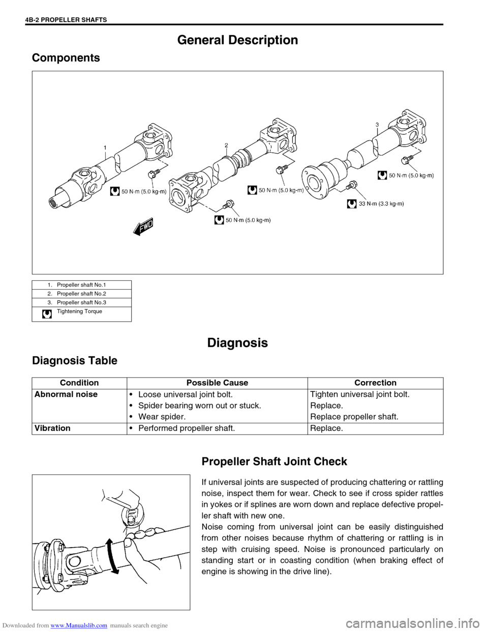
Components
Diagnosis
Diagnosis Table
Propeller Shaft Joint Check
If universal joints are suspected of producing chattering or rattling
noise, inspect them for wear. Check to see if cross spider rattles
in yokes or if splines are worn down and replace defective propel-
ler shaft with new one.
Noise coming from universal joint can be easily distinguished
from other noises because rhythm of chattering or rattling is in
step with cruising speed. Noise is pronounced particularly on
standing start or in coasting condition (when braking effect of
engine is showing in the drive line).
1. Propeller shaft No.1
2. Propeller shaft No.2
3. Propeller shaft No.3
Tightening Torque
Condition Possible Cause Correction
Abnormal noise
Loose universal joint bolt.
Spider bearing worn out or stuck.
Wear spider.Tighten universal joint bolt.
Replace.
Replace propeller shaft.
Vibration
Performed propeller shaft. Replace.
Page 262 of 687
Downloaded from www.Manualslib.com manuals search engine BRAKES 5-1
6F1
6F2
6G
6H
6K
7A
7A1
7B1
7C1
7D
7E
5
9
10
10A
10B
9
10
10A
10B
SECTION 5
BRAKES
CONTENTS
General Description ......................................... 5-3
Diagnosis .......................................................... 5-4
Road Testing Brakes ...................................... 5-4
Brake Fluid Leaks .......................................... 5-4
Substandard or Contaminated Brake Fluid .... 5-4
Diagnosis Table ............................................. 5-5
Brake Pedal Free Height Adjustment ............. 5-8
Brake Pedal Play Check ................................ 5-8
Stop Light Switch Adjustment ........................ 5-8
Excessive Pedal Travel Check ....................... 5-9
Front Brake Disc Check ................................. 5-9
Front Brake Pad Check .................................. 5-9
Rear Brake Shoe Check .............................. 5-10
Master Cylinder and Brake Fluid Level
Check ........................................................... 5-10
Rear Drum Brake Shoe Adjustment ............. 5-11
Parking Brake Inspection and Adjustment ... 5-11
Booster Operation Check ............................. 5-12Fluid Pressure Test
(If Equipped with LSPV) ............................... 5-15
On-Vehicle Service ........................................ 5-17
Air Bleeding of Brake System ...................... 5-17
Brake Hose and Pipe Inspection.................. 5-18
Front Disc Brake .......................................... 5-19
Brake pad ................................................. 5-20
Caliper assembly...................................... 5-22
Brake Disc.................................................... 5-26
Rear Brake ................................................... 5-29
Brake drum............................................... 5-29
Brake shoe ............................................... 5-32
Wheel Cylinder............................................. 5-33
Brake back plate ...................................... 5-34
Master Cylinder .............................................. 5-36
Master Cylinder Reservoir ........................... 5-36
Master Cylinder Assembly ........................... 5-37 WARNING:
For lifting point of vehicle, refer to Section 0A.
WARNING:
For vehicles equipped with Supplement Restraint (Air Bag) System:
Service on and around the air bag system components or wiring must be performed only by an
authorized SUZUKI dealer. Refer to “Air Bag System Components and Wiring Location View” under
“General Description” in air bag system section in order to confirm whether you are performing ser-
vice on or near the air bag system components or wiring. Please observe all WARNINGS and “Ser-
vice Precautions” under “On-Vehicle Service” in air bag system section before performing service
on or around the air bag system components or wiring. Failure to follow WARNINGS could result in
unintentional activation of the system or could render the system inoperative. Either of these two
conditions may result in severe injury.
Technical service work must be started at least 90 seconds after the ignition switch is turned to the
“LOCK” position and the negative cable is disconnected from the battery. Otherwise, the system
may be activated by reserve energy in the Sensing and Diagnostic Module (SDM).
NOTE:
When inspecting and servicing vehicle equipped with ABS, be sure to refer to section 5E first.
All brake fasteners are important attaching parts in that they could affect the performance of vital
parts and systems, and/or could result in major repair expense. They must be replaced with one of
same part number or with an equivalent part if replacement becomes necessary. Do not use a
replacement part of lesser quality or substitute design. Torque values must be used as specified
during reassembly to assure proper retention of all parts. There is to be no welding as it may result
in extensive damage and weakening of the metal.
Page 264 of 687
Downloaded from www.Manualslib.com manuals search engine BRAKES 5-3
General Description
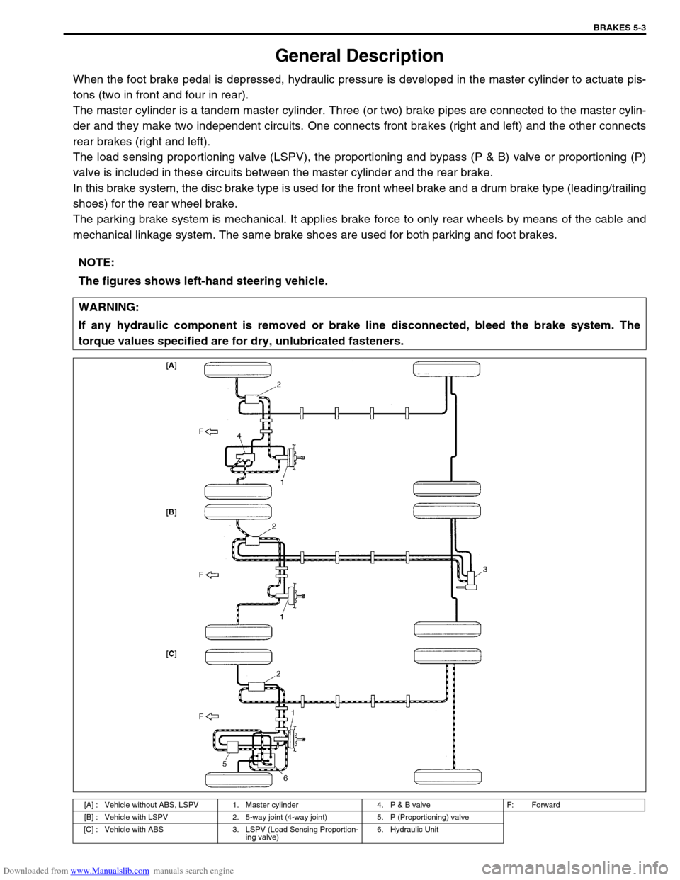
When the foot brake pedal is depressed, hydraulic pressure is developed in the master cylinder to actuate pis-
tons (two in front and four in rear).
The master cylinder is a tandem master cylinder. Three (or two) brake pipes are connected to the master cylin-
der and they make two independent circuits. One connects front brakes (right and left) and the other connects
rear brakes (right and left).
The load sensing proportioning valve (LSPV), the proportioning and bypass (P & B) valve or proportioning (P)
valve is included in these circuits between the master cylinder and the rear brake.
In this brake system, the disc brake type is used for the front wheel brake and a drum brake type (leading/trailing
shoes) for the rear wheel brake.
The parking brake system is mechanical. It applies brake force to only rear wheels by means of the cable and
mechanical linkage system. The same brake shoes are used for both parking and foot brakes.
NOTE:
The figures shows left-hand steering vehicle.
WARNING:
If any hydraulic component is removed or brake line disconnected, bleed the brake system. The
torque values specified are for dry, unlubricated fasteners.
[A] : Vehicle without ABS, LSPV 1. Master cylinder 4. P & B valve F: Forward
[B] : Vehicle with LSPV 2. 5-way joint (4-way joint) 5. P (Proportioning) valve
[C] : Vehicle with ABS 3. LSPV (Load Sensing Proportion-
ing valve)6. Hydraulic Unit
Page 318 of 687
Downloaded from www.Manualslib.com manuals search engine ANTILOCK BRAKE SYSTEM (ABS) 5E-1
6F1
6F2
6G
6H
6K
7A
7A1
7B1
7C1
7D
7E
7F
8E
5E
9
10
10A
10B
10
10A
10B
SECTION 5E
ANTILOCK BRAKE SYSTEM (ABS)
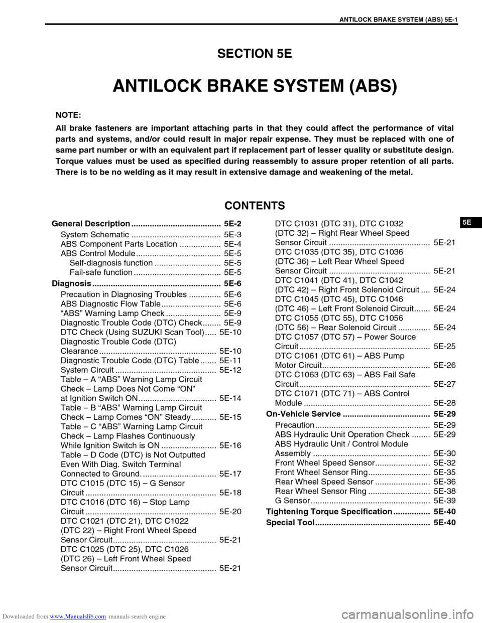
CONTENTS
General Description ....................................... 5E-2
System Schematic ....................................... 5E-3
ABS Component Parts Location .................. 5E-4
ABS Control Module ..................................... 5E-5
Self-diagnosis function ............................. 5E-5
Fail-safe function ...................................... 5E-5
Diagnosis ........................................................ 5E-6
Precaution in Diagnosing Troubles .............. 5E-6
ABS Diagnostic Flow Table .......................... 5E-6
“ABS” Warning Lamp Check ........................ 5E-9
Diagnostic Trouble Code (DTC) Check ........ 5E-9
DTC Check (Using SUZUKI Scan Tool) ..... 5E-10
Diagnostic Trouble Code (DTC)
Clearance ................................................... 5E-10
Diagnostic Trouble Code (DTC) Table ....... 5E-11
System Circuit ............................................ 5E-12
Table – A “ABS” Warning Lamp Circuit
Check – Lamp Does Not Come “ON”
at Ignition Switch ON .................................. 5E-14
Table – B “ABS” Warning Lamp Circuit
Check – Lamp Comes “ON” Steady ........... 5E-15
Table – C “ABS” Warning Lamp Circuit
Check – Lamp Flashes Continuously
While Ignition Switch is ON ........................ 5E-16
Table – D Code (DTC) is Not Outputted
Even With Diag. Switch Terminal
Connected to Ground. ................................ 5E-17
DTC C1015 (DTC 15) – G Sensor
Circuit ......................................................... 5E-18
DTC C1016 (DTC 16) – Stop Lamp
Circuit ......................................................... 5E-20
DTC C1021 (DTC 21), DTC C1022
(DTC 22) – Right Front Wheel Speed
Sensor Circuit ............................................. 5E-21
DTC C1025 (DTC 25), DTC C1026
(DTC 26) – Left Front Wheel Speed
Sensor Circuit ............................................. 5E-21DTC C1031 (DTC 31), DTC C1032
(DTC 32) – Right Rear Wheel Speed
Sensor Circuit ............................................ 5E-21
DTC C1035 (DTC 35), DTC C1036
(DTC 36) – Left Rear Wheel Speed
Sensor Circuit ............................................ 5E-21
DTC C1041 (DTC 41), DTC C1042
(DTC 42) – Right Front Solenoid Circuit .... 5E-24
DTC C1045 (DTC 45), DTC C1046
(DTC 46) – Left Front Solenoid Circuit....... 5E-24
DTC C1055 (DTC 55), DTC C1056
(DTC 56) – Rear Solenoid Circuit .............. 5E-24
DTC C1057 (DTC 57) – Power Source
Circuit ......................................................... 5E-25
DTC C1061 (DTC 61) – ABS Pump
Motor Circuit............................................... 5E-26
DTC C1063 (DTC 63) – ABS Fail Safe
Circuit ......................................................... 5E-27
DTC C1071 (DTC 71) – ABS Control
Module ....................................................... 5E-28
On-Vehicle Service ...................................... 5E-29
Precaution .................................................. 5E-29
ABS Hydraulic Unit Operation Check ........ 5E-29
ABS Hydraulic Unit / Control Module
Assembly ................................................... 5E-30
Front Wheel Speed Sensor........................ 5E-32
Front Wheel Sensor Ring........................... 5E-35
Rear Wheel Speed Sensor ........................ 5E-36
Rear Wheel Sensor Ring ........................... 5E-38
G Sensor .................................................... 5E-39
Tightening Torque Specification ................ 5E-40
Special Tool .................................................. 5E-40 NOTE:
All brake fasteners are important attaching parts in that they could affect the performance of vital
parts and systems, and/or could result in major repair expense. They must be replaced with one of
same part number or with an equivalent part if replacement part of lesser quality or substitute design.
Torque values must be used as specified during reassembly to assure proper retention of all parts.
There is to be no welding as it may result in extensive damage and weakening of the metal.
Page 319 of 687
Downloaded from www.Manualslib.com manuals search engine 5E-2 ANTILOCK BRAKE SYSTEM (ABS)
General Description
The ABS (Antilock Brake System) is a system to prevent each wheel to lock during hard braking or braking on a
slippery road by controlling the fluid pressure from master cylinder to each brake (either brake caliper or wheel
cylinder).
The ABS of this vehicle monitors all four wheels (four sensors) and controls all four wheels when the system is
active.
The component parts of this ABS includes following parts in addition to those of the conventional brake system.
Wheel speed sensor senses revolution speed of each wheel and sends outputs to ABS control module.
In this ABS, ABS hydraulic unit (actuator assembly), ABS control module, pump motor transistor and fail-
safe transistor are combined as one component.
ABS control module sends operation signal to ABS hydraulic unit to control fluid pressure applied to each
wheel cylinder based on signal from each wheel speed sensor so as to prevent wheel from locking.
ABS hydraulic unit operates according to signal from ABS control module and controls fluid pressure applied
to wheel cylinder of each of 4 wheels.
Fail-safe transistor which supplies power to solenoid valve in ABS hydraulic unit.
Pump motor transistor supplies power to pump motor in ABS hydraulic unit.
“ABS” warning lamp lights to inform abnormality when system fails to operate properly.
G sensor which detects body deceleration speed.
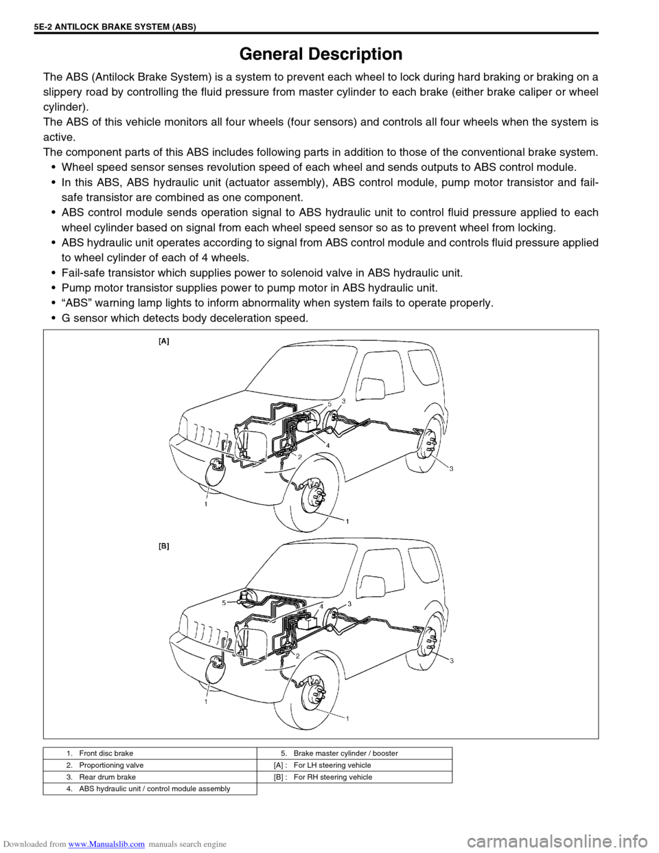
1. Front disc brake 5. Brake master cylinder / booster
2. Proportioning valve [A] : For LH steering vehicle
3. Rear drum brake [B] : For RH steering vehicle
4. ABS hydraulic unit / control module assembly
Page 358 of 687

Downloaded from www.Manualslib.com manuals search engine ENGINE GENERAL INFORMATION AND DIAGNOSIS 6-1
6F2
6G
6H
6K
7A
7A1
7B1
7C1
7D
7E
7F
8B
6
8D
8E
8B
9
10A
10B
SECTION 6
ENGINE GENERAL INFORMATION AND
DIAGNOSIS
GENERAL INFORMATION AND ENGINE DIAGNOSIS ..............................................................................
6-1
ENGINE MECHANICAL ...........................................................................................................................
6A1-1
ENGINE COOLING.....................................................................................................................................
6B-1
ENGINE FUEL ............................................................................................................................................
6C-1
ENGINE AND EMISSION CONTROL SYSTEM ........................................................................................
6E-1
IGNITION SYSTEM ....................................................................................................................................
6F-1
CRANKING SYSTEM .................................................................................................................................
6G-1
CHARGING SYSTEM .................................................................................................................................
6H-1
EXHAUST SYSTEM ...................................................................................................................................
6K-1
CONTENTS
General Information .......................................... 6-3
Statement on Cleanliness and Care ............... 6-3
General Information on Engine Service .......... 6-3
Precaution on fuel system service............... 6-4
Fuel pressure relief procedure .................... 6-5
Fuel leakage check procedure .................... 6-5
Engine Diagnosis .............................................. 6-6
General Description ........................................ 6-6
On-Board Diagnostic System (Vehicle with
Immobilizer Indicator Lamp) ............................ 6-6On-Board Diagnostic System (Vehicle without
Immobilizer Indicator Lamp)............................ 6-9
Precaution in Diagnosing Trouble ................. 6-10
Engine Diagnostic Flow Table ...................... 6-11
Customer problem inspection form
(example) .................................................. 6-13
Malfunction indicator lamp (MIL) check..... 6-14
Diagnostic trouble code (DTC) check ....... 6-14
Diagnostic trouble code (DTC)
clearance................................................... 6-15 WARNING:
For vehicles equipped with Supplemental Restraint (Air Bag) System :
Service on and around the air bag system components or wiring must be performed only by an
authorized SUZUKI dealer. Refer to “Air Bag System Components and Wiring Location View” under
“General Description” in air bag system section in order to confirm whether you are performing ser-
vice on or near the air bag system components or wiring. Please observe all WARNINGS and “Ser-
vice Precautions” under “On-Vehicle Service” in air bag system section before performing service
on or around the air bag system components or wiring. Failure to follow WARNINGS could result in
unintentional activation of the system or could render the system inoperative. Either of these two
conditions may result in severe injury.
Technical service work must be started at least 90 seconds after the ignition switch is turned to the
“LOCK” position and the negative cable is disconnected from the battery. Otherwise, the system
may be activated by reserve energy in the Sensing and Diagnostic Module (SDM).
NOTE:
Whether the following systems (parts) are used in the particular vehicle or not depends on vehicle
specifications. Be sure to bear this in mind when performing service work.
EGR valve
Heated oxygen sensor(s) or CO adjusting resistor
Three-way catalytic converter (TWC) and warm up three-way catalytic converter (WU-TWC)
Page 363 of 687
Downloaded from www.Manualslib.com manuals search engine 6-6 ENGINE GENERAL INFORMATION AND DIAGNOSIS
Engine Diagnosis
General Description
This vehicle is equipped with an engine and emission control system which are under control of ECM.
The engine and emission control system in this vehicle are controlled by ECM. ECM has an On-Board Diagnos-
tic system which detects a malfunction in this system and abnormality of those parts that influence the engine
exhaust emission. When diagnosing engine troubles, be sure to have full understanding of the outline of “On-
Board Diagnostic System” and each item in “Precaution in Diagnosing Trouble” and execute diagnosis accord-
ing to “ENGINE DIAGNOSTIC FLOW TABLE”.
There is a close relationship between the engine mechanical, engine cooling system, ignition system, exhaust
system, etc. and the engine and emission control system in their structure and operation. In case of an engine
trouble, even when the malfunction indicator lamp (MIL) doesn’t turn ON, it should be diagnosed according to
this flow table.
On-Board Diagnostic System (Vehicle with
Immobilizer Indicator Lamp)
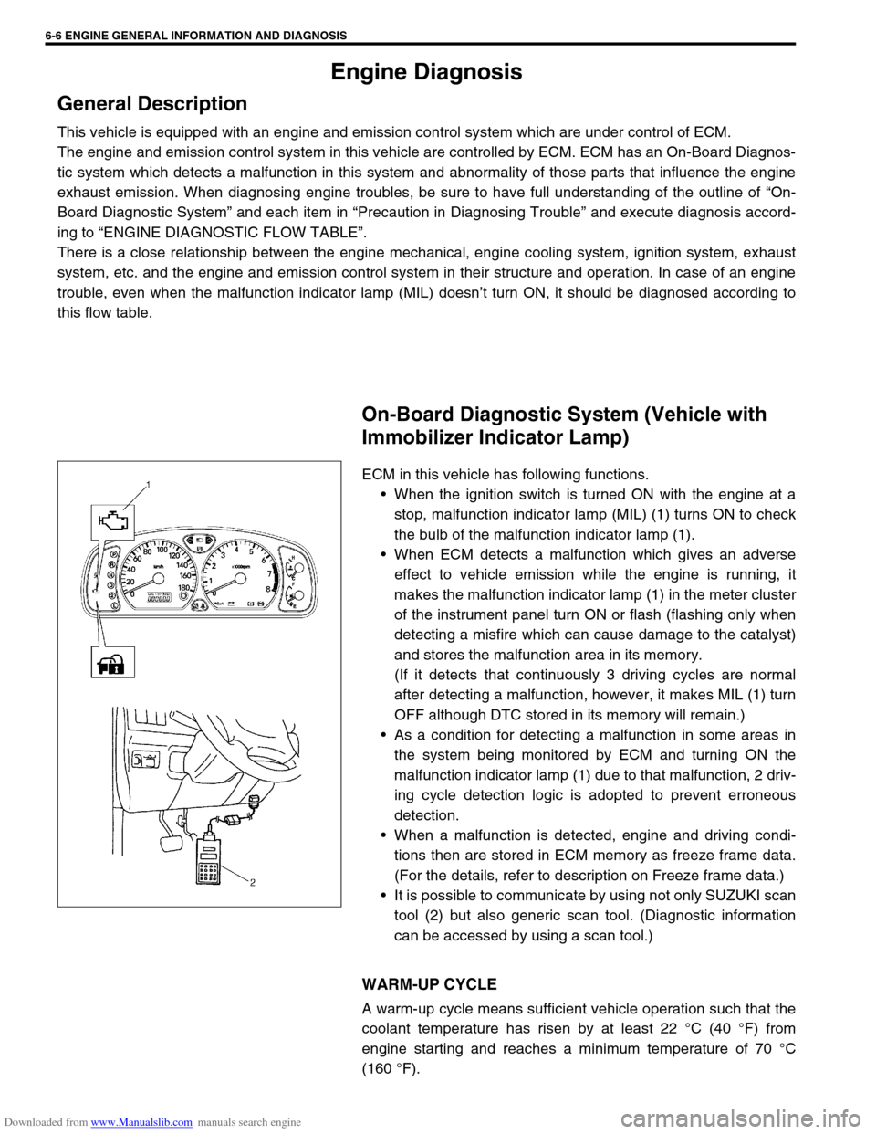
ECM in this vehicle has following functions.
When the ignition switch is turned ON with the engine at a
stop, malfunction indicator lamp (MIL) (1) turns ON to check
the bulb of the malfunction indicator lamp (1).
When ECM detects a malfunction which gives an adverse
effect to vehicle emission while the engine is running, it
makes the malfunction indicator lamp (1) in the meter cluster
of the instrument panel turn ON or flash (flashing only when
detecting a misfire which can cause damage to the catalyst)
and stores the malfunction area in its memory.
(If it detects that continuously 3 driving cycles are normal
after detecting a malfunction, however, it makes MIL (1) turn
OFF although DTC stored in its memory will remain.)
As a condition for detecting a malfunction in some areas in
the system being monitored by ECM and turning ON the
malfunction indicator lamp (1) due to that malfunction, 2 driv-
ing cycle detection logic is adopted to prevent erroneous
detection.
When a malfunction is detected, engine and driving condi-
tions then are stored in ECM memory as freeze frame data.
(For the details, refer to description on Freeze frame data.)
It is possible to communicate by using not only SUZUKI scan
tool (2) but also generic scan tool. (Diagnostic information
can be accessed by using a scan tool.)
WARM-UP CYCLE
A warm-up cycle means sufficient vehicle operation such that the
coolant temperature has risen by at least 22 °C (40 °F) from
engine starting and reaches a minimum temperature of 70 °C
(160 °F).