Lever SUZUKI JIMNY 2005 3.G Service Owner's Manual
[x] Cancel search | Manufacturer: SUZUKI, Model Year: 2005, Model line: JIMNY, Model: SUZUKI JIMNY 2005 3.GPages: 687, PDF Size: 13.38 MB
Page 181 of 687

Downloaded from www.Manualslib.com manuals search engine 3D-8 FRONT SUSPENSION
Diagnosis
Diagnosis Table
For description not found in the table below, refer to “Diagnosis Table” in Section 3.
4WD CONTROL SYSTEM
4WD CONTROL SYSTEM DIAGNOSTIC FLOW TABLE
Before performing the trouble diagnosis, check that the air locking hub assemblies are in good condition and
there is no air leakage from vacuum hoses and vacuum pipe. Refer to “4WD Control System Check” in this sec-
tion for air leakage.
[NOTES ON SYSTEM CIRCUIT INSPECTION]
Be sure to read “Precautions for Electrical Circuit Service” in Section 0A before circuit inspection and
observe what is written there.
For system circuit, refer to the figure of “System Circuit” in this section. Condition Possible Cause Correction
4WD Indicator light
flashingHub locking procedure error
Defective VSV2
Defective vacuum switch
Defective check valve or vacuum tank
Air leak from vacuum circuit
Clogged vacuum hose or pipe
Faulty 4WD controllerShift transfer shift control lever
2WD → 4WD once again
Replace
Replace
Replace
Check and repair
Replace
Check and replace
2WD/4WD switching
errorDefective air locking hub assembly
Abnormality in 4WD control system
Air leakage from vacuum circuit
Clogged vacuum hose or pipe
Defective check valve or vacuum tankReplace
Inspect referring to “4WD Control
System Diagnostic Flow Table”
Check and replace
Replace
Replace
Step Action Yes No
1 Check ground circuit.
1) Disconnect coupler from 4WD controller
with ignition switch OFF.
2) Check for proper connection to 4WD con-
troller at all terminals.
3) If OK, check continuity between A5 terminal
and body ground.
Is there continuity between A5 terminal and
body ground?Go to Step 2.“B” wire is open.
2 Check power circuit.
1) Disconnect coupler from 4WD controller.
2) Turn ignition switch ON.
3) Check voltage between A10 terminal and
ground.
Is it 10 – 14 V?Go to Step 3.“Y/R” circuit is open or
short.
Page 182 of 687

Downloaded from www.Manualslib.com manuals search engine FRONT SUSPENSION 3D-9
3 Check 4WD switch circuit.
1) Connect coupler to 4WD controller.
2) Turn ignition switch ON and check voltage
between A7 terminal and ground.
Transfer lever is in 2H : about 10 – 14 V
Transfer lever is in 4L or 4H : about 0 V
Is check result satisfactory?Go to Step 4. Check 4WD switch (refer
to “4WD Switch” in Sec-
tion 7D), “Bl/B” and “B”
circuits of 4WD switch.
If OK, substitute a known-
good 4WD controller and
recheck.
4 Check VSV1 circuit.
1) Turn ignition switch ON.
2) Check voltage between A1 terminal and
ground.
Is it 10 – 14 V when transfer lever is in 4H or 4L
range and about 0 V for 10 seconds after it is
shifted to 2H range?Go to Step 5. Check VSV1 (refer to
“4WD Control System
Check” in this section),
“Y/R” and “Gr/B” circuits
of VSV1.
If OK, substitute a known-
good 4WD controller and
recheck.
5 Check VSV2 circuit.
1) Turn ignition switch ON.
2) Check voltage between A2 terminal and
ground.
Is it 10 – 14 V when transfer lever is in 2H range
and about 0 V for 5 seconds after it is shifted to
4H or 4L range?Go to Step 6. Check VSV2 (refer to
“4WD Control System
Check” in this section),
“Y/R” and “Gr/R” circuits
of VSV2.
If OK, substitute a known-
good 4WD controller and
recheck.
6 Check vacuum switch circuit.
1) Turn ignition switch ON (stating engine).
2) Check voltage between A6 terminal and
ground.
Is it 10 – 14 V when transfer lever is in 2H range
and about 0 V for 5 seconds after it is shifted to
4H or 4L range?Go to Step 7. Check vacuum switch
(refer to “4WD Control
System Check” in this
section), “Gr” and “B” cir-
cuits of vacuum switch.
If OK, substitute a known-
good 4WD controller and
recheck.
7 Check 4WD indicator light circuit.
1) Turn ignition switch ON.
2) Check voltage between A3 terminal and
ground.
Is it 10 – 14 V when transfer lever is in 2H range
and about 0 V within 15 seconds after it is
shifted to 4H or 4L range?Substitute a known-good
4WD controller and
recheck.Check “Bl” circuit (includ-
ing indicator light and
combination meter refer to
“Combination Meter” in
Section 8).
If OK, substitute a known-
good 4WD controller and
recheck. Step Action Yes No
Page 183 of 687

Downloaded from www.Manualslib.com manuals search engine 3D-10 FRONT SUSPENSION
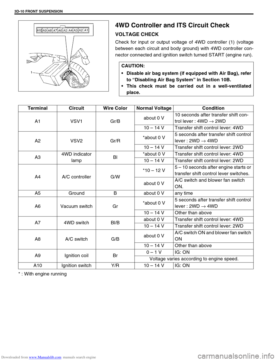
4WD Controller and ITS Circuit Check
VOLTAGE CHECK
Check for input or output voltage of 4WD controller (1) (voltage
between each circuit and body ground) with 4WD controller con-
nector connected and ignition switch turned START (engine run).
* : With engine runningCAUTION:
Disable air bag system (if equipped with Air Bag), refer
to “Disabling Air Bag System” in Section 10B.
This check must be carried out in a well-ventilated
place.
Terminal Circuit Wire Color Normal Voltage Condition
A1 VSV1 Gr/Babout 0 V10 seconds after transfer shift con-
trol lever : 4WD → 2WD
10 – 14 V Transfer shift control lever: 4WD
A2 VSV2 Gr/R*about 0 V5 seconds after transfer shift control
lever : 2WD → 4WD
10 – 14 V Transfer shift control lever: 2WD
A34WD indicator
lampBl*about 0 V Transfer shift control lever: 4WD
10 – 14 V Transfer shift control lever: 2WD
A4 A/C controller G/W*10 – 12 V5 – 10 seconds after engine starts or
transfer shift control lever switches.
about 0 VA/C switch and blower fan switch
ON.
A5 Ground B about 0 V any time
A6 Vacuum switch Gr*about 0 V5 seconds after transfer shift control
lever : 2WD → 4WD
10 – 14 V Other than above
A7 4WD switch Bl/Babout 0 V Transfer shift control lever: 4WD
10 – 14 V Transfer shift control lever: 2WD
A8 A/C switch G/Babout 0 VA/C switch ON and blower fan switch
ON
10 – 14 V Other than above
A9 Ignition coil Br0 – 1 V IG: ON
Voltage varies according to engine speed.
A10 Ignition switch Y/R 10 – 14 V IG: ON
Page 184 of 687

Downloaded from www.Manualslib.com manuals search engine FRONT SUSPENSION 3D-11
4WD Control System Check
AIR LOCKING HUB
1) Start engine and shift transfer shift control lever to 2H posi-
tion.
2) Connect vacuum pump gauge (special tool) to the spindle
hose (2) which is disconnected from upper side pipe as
shown. Apply vacuum and check operating sound from air
locking hub (1).
If there is not operating sound, replace air locking hub
assembly.
Vacuum specification
More than 40 kPa (0.40 kg/cm
2, 5.70 Psi)
Special tool
(A) : 09917-47910
3) Connect hose, then start engine and shift transfer shift con-
trol lever to 4H or 4L position.
4) Connect vacuum pump gauge to the spindle hose (2) dis-
connected from lower side pipe.
Apply vacuum and check operating sound from air locking
hub (1).
If there is no operating sound, replace air locking hub
assembly.
Vacuum specification
More than 40 kPa (0.40 kg/cm
2, 5.70 Psi)
Special tool
(A) : 09917-47910
VSV1 AND VSV2
1) Disconnect coupler from VSV1 (1) (VSV2) (2) and check
resistance between two terminals of VSV1 (1) (VSV2) (2).
If resistance is out of specification, replace.
Resistance of VSV1 and VSV2
: 33 – 39
Ω
Page 236 of 687

Downloaded from www.Manualslib.com manuals search engine REAR SUSPENSION 3E-17
16) Upon completion of all jobs, depress brake pedal with about
30 kg (66 lbs) load over ten times so as to obtain proper
drum-to shoe clearance.
Adjust parking brake cable. (For adjustment, refer to “Parking
Brake Check and Adjustment” in Section 5.)
17) Tighten parking brake lever cover screws.
18) Check to ensure that brake drum is free from dragging and
proper braking is obtained. Then remove vehicle from hoist
and perform brake test (foot brake and parking brake).
19) Check each installed part for oil leakage.
Rear Axle Shaft Inner Oil Seal
REMOVAL
1) Remove rear axle shaft. For details, refer to “Rear Axle Shaft
and Wheel Bearing” in this section.
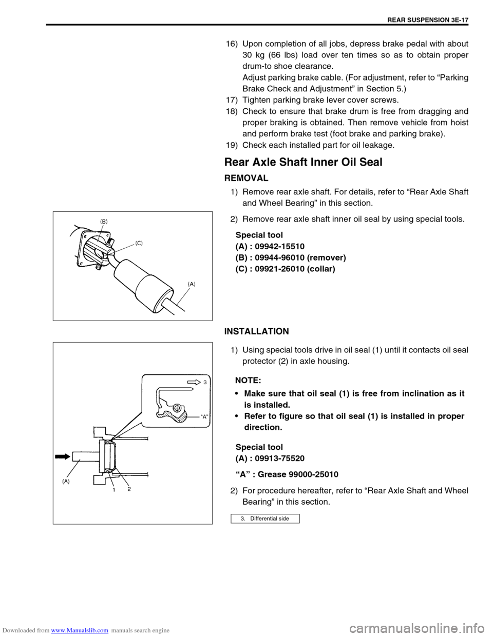
2) Remove rear axle shaft inner oil seal by using special tools.
Special tool
(A) : 09942-15510
(B) : 09944-96010 (remover)
(C) : 09921-26010 (collar)
INSTALLATION
1) Using special tools drive in oil seal (1) until it contacts oil seal
protector (2) in axle housing.
Special tool
(A) : 09913-75520
“A” : Grease 99000-25010
2) For procedure hereafter, refer to “Rear Axle Shaft and Wheel
Bearing” in this section.
NOTE:
Make sure that oil seal (1) is free from inclination as it
is installed.
Refer to figure so that oil seal (1) is installed in proper
direction.
3. Differential side
Page 263 of 687

Downloaded from www.Manualslib.com manuals search engine 5-2 BRAKES
Master Cylinder ............................................ 5-38
Fill Reservoir ................................................ 5-40
LSPV (Load Sensing Proportioning Valve)
Assembly (If Equipped) ................................. 5-42
LSPV Assembly ........................................... 5-43
P (Proportioning) Valve ................................. 5-44
Brake Booster ................................................ 5-45
Inspection and adjustment ....................... 5-46
Brake Hose/Pipe .......................................... 5-48Front brake hose/pipe ............................... 5-48
Rear Brake Hose/Pipe .................................. 5-51
Parking Brake Lever/Cable ........................... 5-52
Parking brake lever ................................... 5-52
Parking Brake Cable ..................................... 5-53
Tightening Torque Specifications ................. 5-54
Required Service Material.............................. 5-54
Special Tool .................................................... 5-55
Page 272 of 687

Downloaded from www.Manualslib.com manuals search engine BRAKES 5-11
Rear Drum Brake Shoe Adjustment
Rear brake has self-adjusting mechanism but it does require
adjustment for proper drum to shoe clearance when brake shoe
has been replaced or brake drum has been removed for some
other service.
Adjustment is automatically accomplished by depressing brake
pedal about 30 times with approximately 30 kg (66 Ibs) load after
all parts are installed.
Then check brake drum for dragging and brake system for proper
performance. After lowering vehicle from hoist, brake test should
be performed.
Parking Brake Inspection and Adjustment
INSPECTION
Hold center of parking brake lever grip and pull it up with 20 kg
(44 Ibs) force.
With parking brake lever pulled up as above, count ratchet
notches.
There should be 6 to 8 notches.
Also, check if both right and left rear wheels are locked firmly. To
count number of notches easily, listen to click sounds that ratchet
makes while pulling parking brake lever without pressing its but-
ton.
One click sound corresponds to one notch.NOTE:
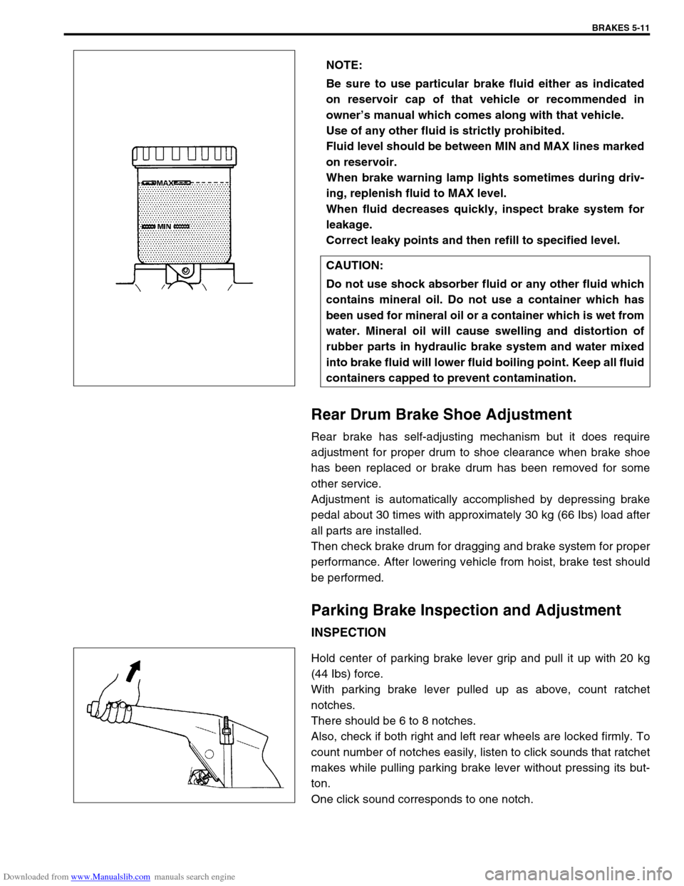
Be sure to use particular brake fluid either as indicated
on reservoir cap of that vehicle or recommended in
owner’s manual which comes along with that vehicle.
Use of any other fluid is strictly prohibited.
Fluid level should be between MIN and MAX lines marked
on reservoir.
When brake warning lamp lights sometimes during driv-
ing, replenish fluid to MAX level.
When fluid decreases quickly, inspect brake system for
leakage.
Correct leaky points and then refill to specified level.
CAUTION:
Do not use shock absorber fluid or any other fluid which
contains mineral oil. Do not use a container which has
been used for mineral oil or a container which is wet from
water. Mineral oil will cause swelling and distortion of
rubber parts in hydraulic brake system and water mixed
into brake fluid will lower fluid boiling point. Keep all fluid
containers capped to prevent contamination.
Page 273 of 687

Downloaded from www.Manualslib.com manuals search engine 5-12 BRAKES
If number of notches is out of specification, adjust cable by refer-
ring to adjustment procedure described on the following so as to
obtain specified parking brake stroke.
ADJUSTMENT
After confirming that above 5 conditions are all satisfied, adjust
parking brake lever stroke by loosening or tightening adjusting nut
(3) indicated in figure.
Parking brake stroke (when lever is pulled up at 200 N (20
kg, 44 Ibs) : 6 – 8 notches
Booster Operation Check
There are two ways to perform this inspection, with and without a
tester. Ordinarily, it is possible to roughly determine its condition
without using a tester.NOTE:
Check tooth tip of each notch for damage or wear. If any
damage or wear is found, replace parking brake lever.
NOTE:
Make sure for following conditions before cable adjust-
ment.
No air is trapped in brake system.
Brake pedal travel is proper.
Brake pedal has been depressed a few times with
about 30 kg (66 Ibs) load.
Parking brake lever (1) has been pulled up a few times
with about 20 kg force.
Rear brake shoes are not worn beyond limit, and self
adjusting mechanism operates properly.
NOTE:
Check brake drum for dragging after adjustment.
2. Brake cable
NOTE:
For this check, make sure that no air is in hydraulic line.
Page 277 of 687

Downloaded from www.Manualslib.com manuals search engine 5-16 BRAKES
4) If rear brake pressure is not within specification, adjust it by
changing stay position as follows.
If rear brake pressure is higher than specification, move stay
“A” to direction “l” and if it is lower, to direction “r”.
Repeat steps 3) and 4) until rear brake pressure is within
specification.
After adjustment, be sure to torque bolt to specification.
Tightening torque
LSPV adjust bolt
(a) : 25 N·m (2.5 kg-m, 18 Ib-ft)
5) Disconnect brake pipe (2) (connecting between master cylin-
der secondary side and 4-way joint) from master cylinder (1).
Tighten plug (special tool) to master cylinder.
Depress brake pedal. If rear brake pressure is 95 – 100
kg/cm
2 when front brake pressure is 100 kg/cm2, it means
that front fail-safe system functions properly.
Special tool
(A) : 09956-02210
1. LSPV lever
2. LSPV spring
3. LSPV stay
Front brake Rear brake
10000 kPa
100 kg/cm
2
1422 psi9500 – 10000 kPa
95 – 100 kg/cm
2
1350 – 1422 psi
Page 289 of 687

Downloaded from www.Manualslib.com manuals search engine 5-28 BRAKES
CHECK FOR FRONT BRAKE AFTER INSTALLATION
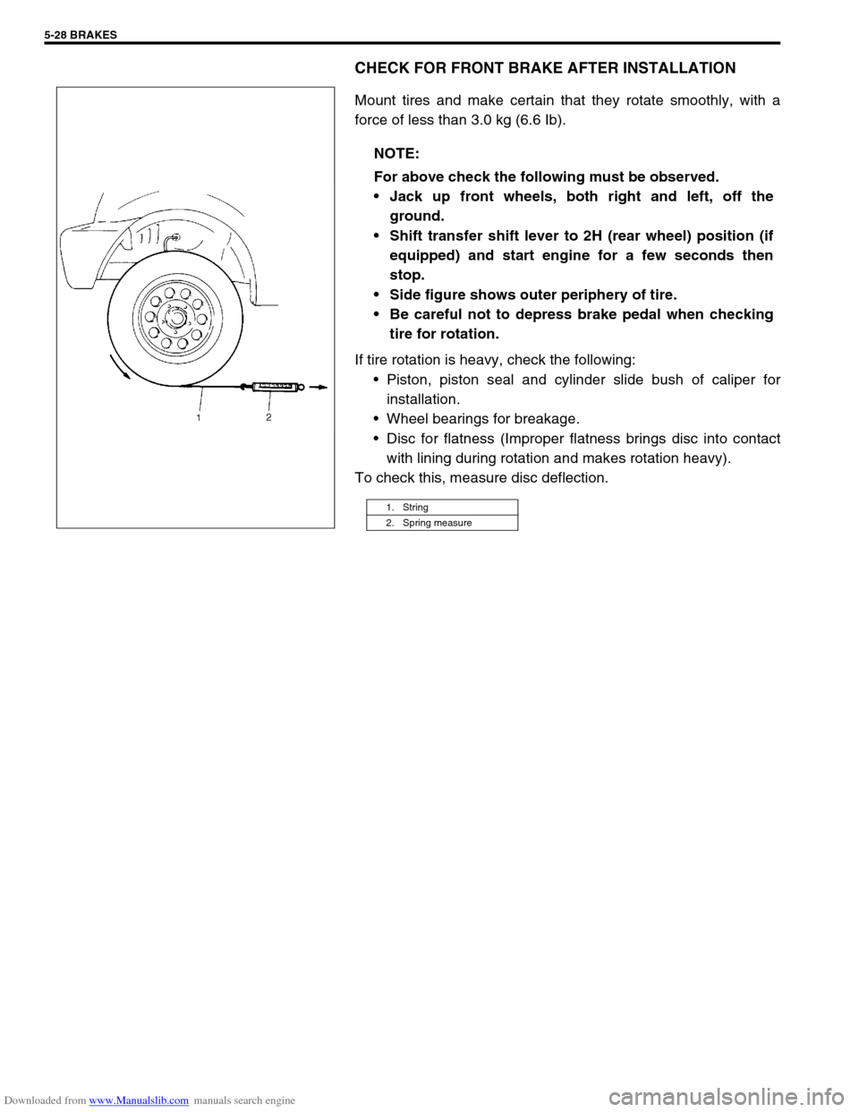
Mount tires and make certain that they rotate smoothly, with a
force of less than 3.0 kg (6.6 Ib).
If tire rotation is heavy, check the following:
Piston, piston seal and cylinder slide bush of caliper for
installation.
Wheel bearings for breakage.
Disc for flatness (Improper flatness brings disc into contact
with lining during rotation and makes rotation heavy).
To check this, measure disc deflection.NOTE:
For above check the following must be observed.
Jack up front wheels, both right and left, off the
ground.
Shift transfer shift lever to 2H (rear wheel) position (if
equipped) and start engine for a few seconds then
stop.
Side figure shows outer periphery of tire.
Be careful not to depress brake pedal when checking
tire for rotation.
1. String
2. Spring measure