contact SUZUKI JIMNY 2005 3.G Service Owner's Manual
[x] Cancel search | Manufacturer: SUZUKI, Model Year: 2005, Model line: JIMNY, Model: SUZUKI JIMNY 2005 3.GPages: 687, PDF Size: 13.38 MB
Page 162 of 687
Downloaded from www.Manualslib.com manuals search engine STEERING WHEEL AND COLUMN 3C-9
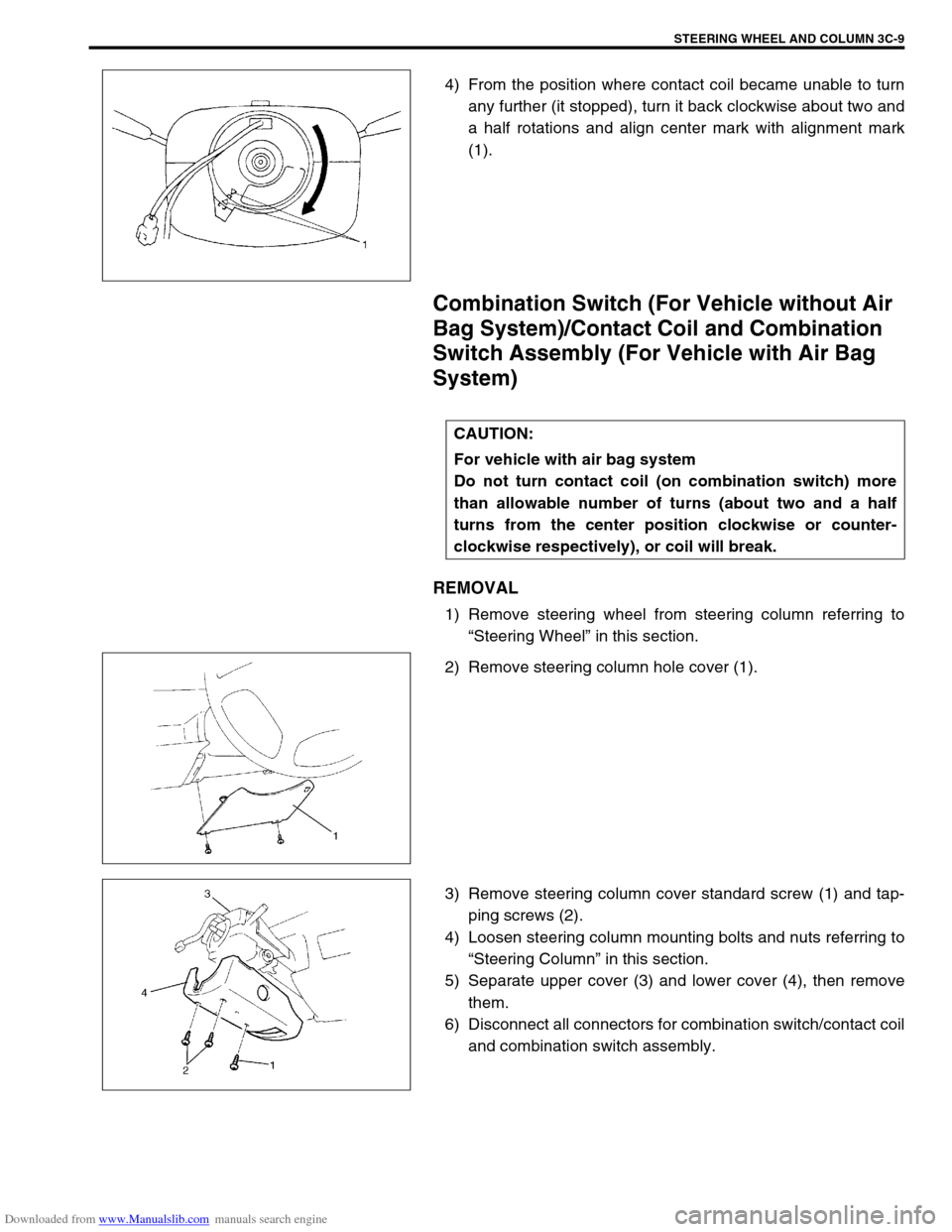
4) From the position where contact coil became unable to turn
any further (it stopped), turn it back clockwise about two and
a half rotations and align center mark with alignment mark
(1).
Combination Switch (For Vehicle without Air
Bag System)/Contact Coil and Combination
Switch Assembly (For Vehicle with Air Bag
System)
REMOVAL
1) Remove steering wheel from steering column referring to
“Steering Wheel” in this section.
2) Remove steering column hole cover (1).
3) Remove steering column cover standard screw (1) and tap-
ping screws (2).
4) Loosen steering column mounting bolts and nuts referring to
“Steering Column” in this section.
5) Separate upper cover (3) and lower cover (4), then remove
them.
6) Disconnect all connectors for combination switch/contact coil
and combination switch assembly.
CAUTION:
For vehicle with air bag system
Do not turn contact coil (on combination switch) more
than allowable number of turns (about two and a half
turns from the center position clockwise or counter-
clockwise respectively), or coil will break.
Page 163 of 687
Downloaded from www.Manualslib.com manuals search engine 3C-10 STEERING WHEEL AND COLUMN
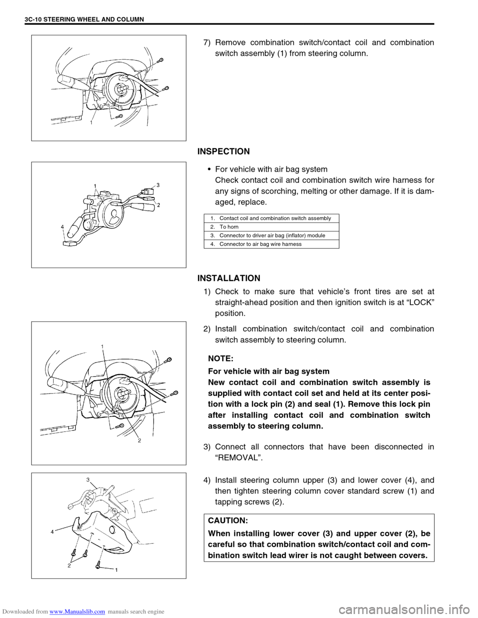
7) Remove combination switch/contact coil and combination
switch assembly (1) from steering column.
INSPECTION
For vehicle with air bag system
Check contact coil and combination switch wire harness for
any signs of scorching, melting or other damage. If it is dam-
aged, replace.
INSTALLATION
1) Check to make sure that vehicle’s front tires are set at
straight-ahead position and then ignition switch is at “LOCK”
position.
2) Install combination switch/contact coil and combination
switch assembly to steering column.
3) Connect all connectors that have been disconnected in
“REMOVAL”.
4) Install steering column upper (3) and lower cover (4), and
then tighten steering column cover standard screw (1) and
tapping screws (2).
1. Contact coil and combination switch assembly
2. To horn
3. Connector to driver air bag (inflator) module
4. Connector to air bag wire harness
NOTE:
For vehicle with air bag system
New contact coil and combination switch assembly is
supplied with contact coil set and held at its center posi-
tion with a lock pin (2) and seal (1). Remove this lock pin
after installing contact coil and combination switch
assembly to steering column.
CAUTION:
When installing lower cover (3) and upper cover (2), be
careful so that combination switch/contact coil and com-
bination switch lead wirer is not caught between covers.
Page 165 of 687
Downloaded from www.Manualslib.com manuals search engine 3C-12 STEERING WHEEL AND COLUMN
REMOVAL
1) Disconnect negative battery cable at battery terminal.
2) For vehicle equipped with air bag system, disable air bag
system referring to “Disabling Air Bag System” in Section
10B.
3) If necessary, remove steering wheel and combination switch
assembly referring to “Steering Wheel” and “Combination
switch/Contact Coil and Combination Switch Assembly” in
this section.
If not removing steering wheel and/or combination switch
assembly, perform the following procedure.
a) Turn steering wheel so that vehicle’s front tires are at
straight ahead position.
b) Turn ignition switch to “LOCK” position and remove key.
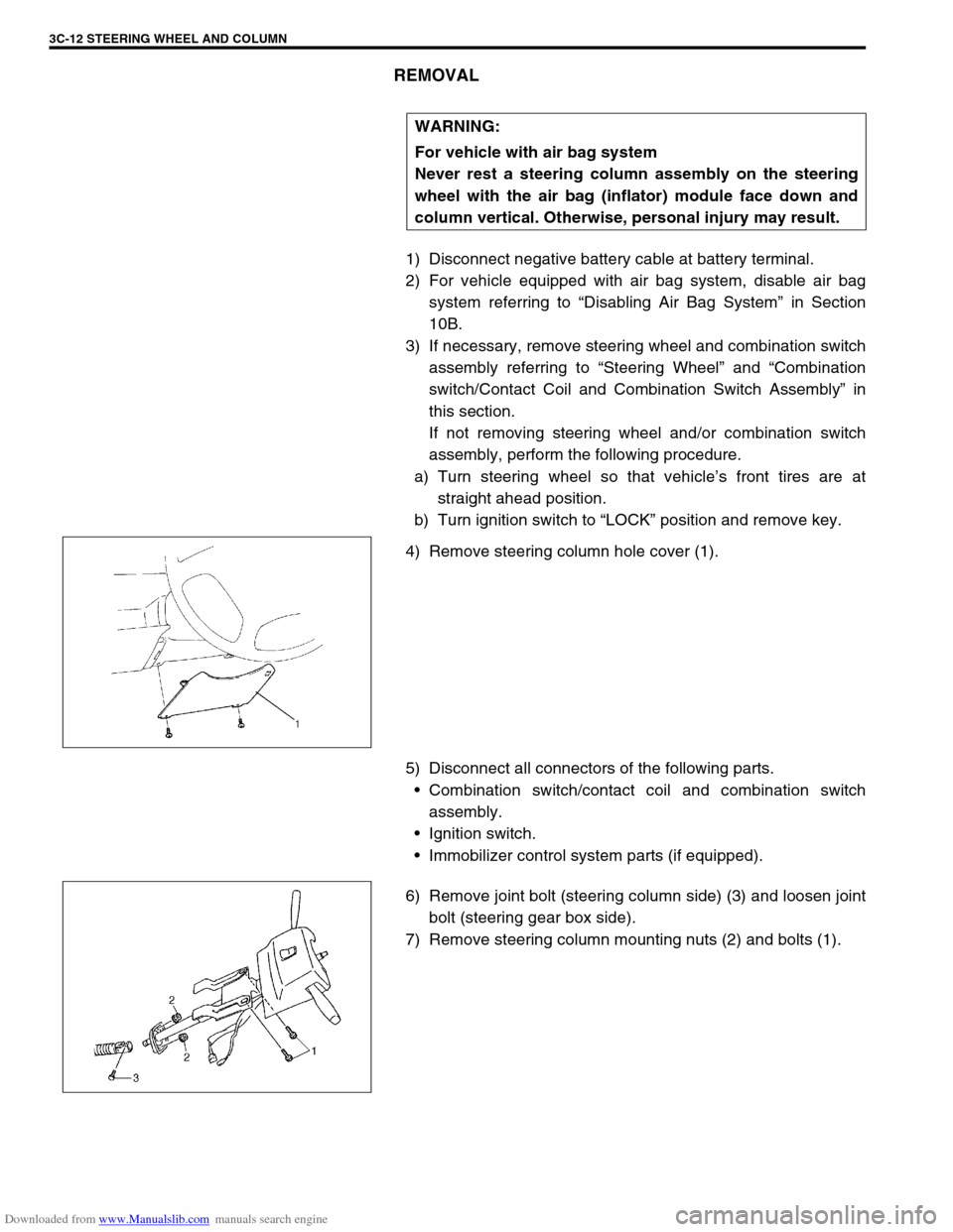
4) Remove steering column hole cover (1).
5) Disconnect all connectors of the following parts.
Combination switch/contact coil and combination switch
assembly.
Ignition switch.
Immobilizer control system parts (if equipped).
6) Remove joint bolt (steering column side) (3) and loosen joint
bolt (steering gear box side).
7) Remove steering column mounting nuts (2) and bolts (1).WARNING:
For vehicle with air bag system
Never rest a steering column assembly on the steering
wheel with the air bag (inflator) module face down and
column vertical. Otherwise, personal injury may result.
Page 168 of 687
Downloaded from www.Manualslib.com manuals search engine STEERING WHEEL AND COLUMN 3C-15
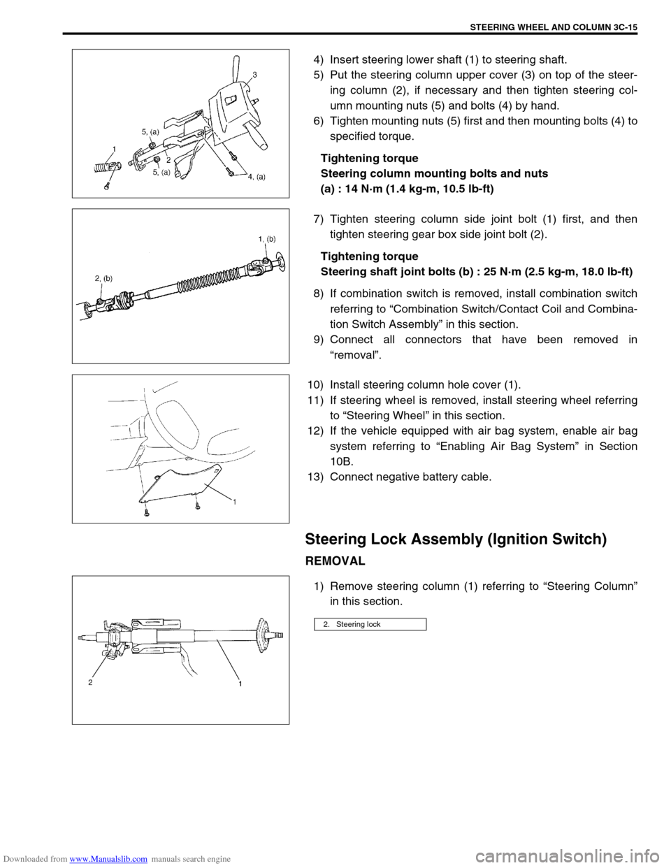
4) Insert steering lower shaft (1) to steering shaft.
5) Put the steering column upper cover (3) on top of the steer-
ing column (2), if necessary and then tighten steering col-
umn mounting nuts (5) and bolts (4) by hand.
6) Tighten mounting nuts (5) first and then mounting bolts (4) to
specified torque.
Tightening torque
Steering column mounting bolts and nuts
(a) : 14 N·m (1.4 kg-m, 10.5 lb-ft)
7) Tighten steering column side joint bolt (1) first, and then
tighten steering gear box side joint bolt (2).
Tightening torque
Steering shaft joint bolts (b) : 25 N·m (2.5 kg-m, 18.0 lb-ft)
8) If combination switch is removed, install combination switch
referring to “Combination Switch/Contact Coil and Combina-
tion Switch Assembly” in this section.
9) Connect all connectors that have been removed in
“removal”.
10) Install steering column hole cover (1).
11) If steering wheel is removed, install steering wheel referring
to “Steering Wheel” in this section.
12) If the vehicle equipped with air bag system, enable air bag
system referring to “Enabling Air Bag System” in Section
10B.
13) Connect negative battery cable.
Steering Lock Assembly (Ignition Switch)
REMOVAL
1) Remove steering column (1) referring to “Steering Column”
in this section.
2. Steering lock
Page 169 of 687
Downloaded from www.Manualslib.com manuals search engine 3C-16 STEERING WHEEL AND COLUMN
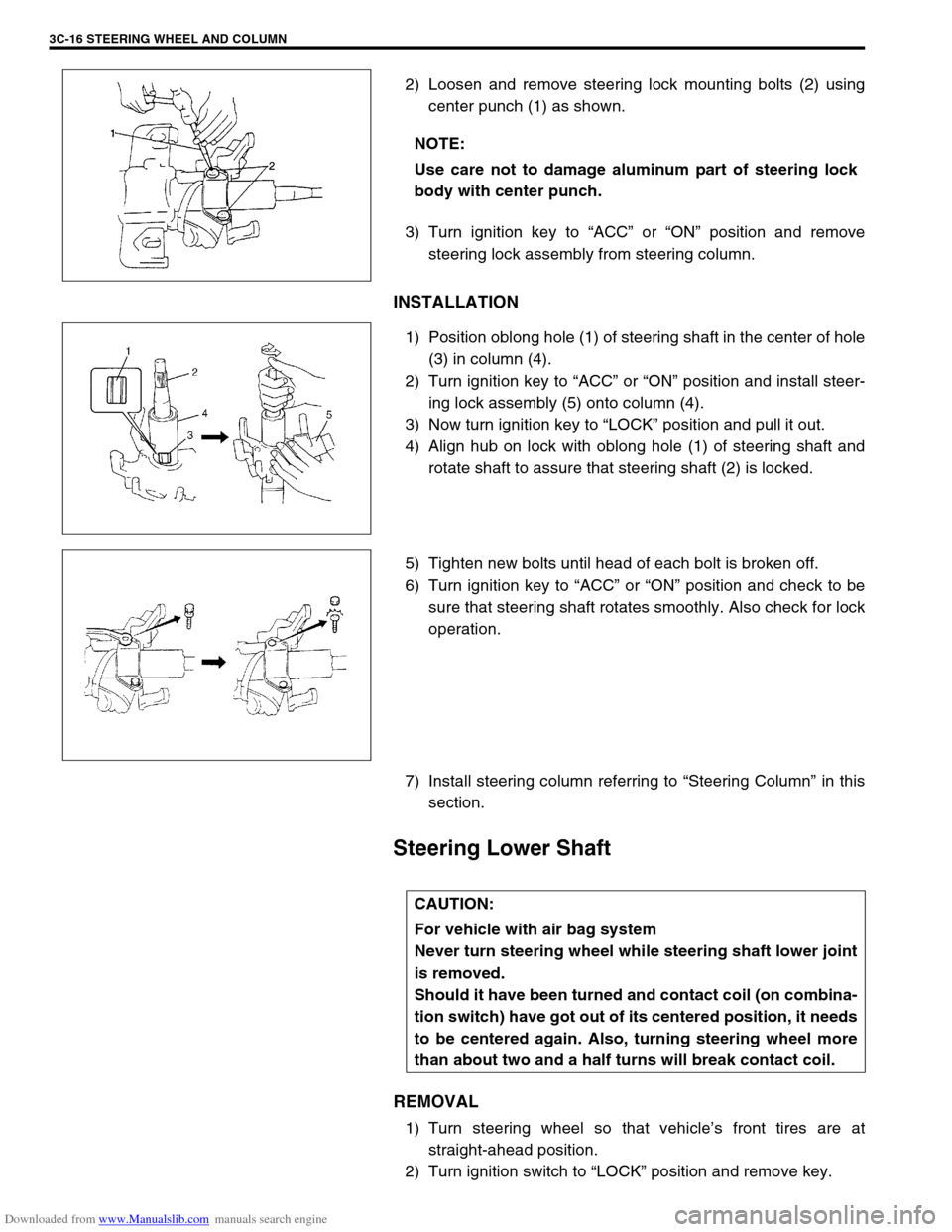
2) Loosen and remove steering lock mounting bolts (2) using
center punch (1) as shown.
3) Turn ignition key to “ACC” or “ON” position and remove
steering lock assembly from steering column.
INSTALLATION
1) Position oblong hole (1) of steering shaft in the center of hole
(3) in column (4).
2) Turn ignition key to “ACC” or “ON” position and install steer-
ing lock assembly (5) onto column (4).
3) Now turn ignition key to “LOCK” position and pull it out.
4) Align hub on lock with oblong hole (1) of steering shaft and
rotate shaft to assure that steering shaft (2) is locked.
5) Tighten new bolts until head of each bolt is broken off.
6) Turn ignition key to “ACC” or “ON” position and check to be
sure that steering shaft rotates smoothly. Also check for lock
operation.
7) Install steering column referring to “Steering Column” in this
section.
Steering Lower Shaft
REMOVAL
1) Turn steering wheel so that vehicle’s front tires are at
straight-ahead position.
2) Turn ignition switch to “LOCK” position and remove key. NOTE:
Use care not to damage aluminum part of steering lock
body with center punch.
CAUTION:
For vehicle with air bag system
Never turn steering wheel while steering shaft lower joint
is removed.
Should it have been turned and contact coil (on combina-
tion switch) have got out of its centered position, it needs
to be centered again. Also, turning steering wheel more
than about two and a half turns will break contact coil.
Page 172 of 687
Downloaded from www.Manualslib.com manuals search engine STEERING WHEEL AND COLUMN 3C-19
6) Check steering shaft joints and shaft for any damages such
as crack, breakage, malfunction or excessive play.
If anything is found faulty, replace as lower joint assembly or
column assembly.
7) Check steering shaft for smooth rotation.
If found defective, replace as column assembly.
8) Check steering shaft and column for bend, cracks or defor-
mation.
If found defective, replace.
Tightening Torque Specifications
Required Service Material
Special Tool
Fastening partTightening torque
Nm kg-m lb-ft
Driver air bag (inflator) module bolts 9 0.9 6.5
Steering shaft nut 33 3.3 23.5
Steering column mounting bolts and nuts 14 1.4 10.5
Steering shaft joint bolts 25 2.5 18.0
Material Recommended SUZUKI product Use
Water tight sealant SEALING COMPOUND 366E
(99000-31090)To apply to steering column seal.
Lithium grease SUZUKI GREASE CE-T
(99000-25290)Contact plate
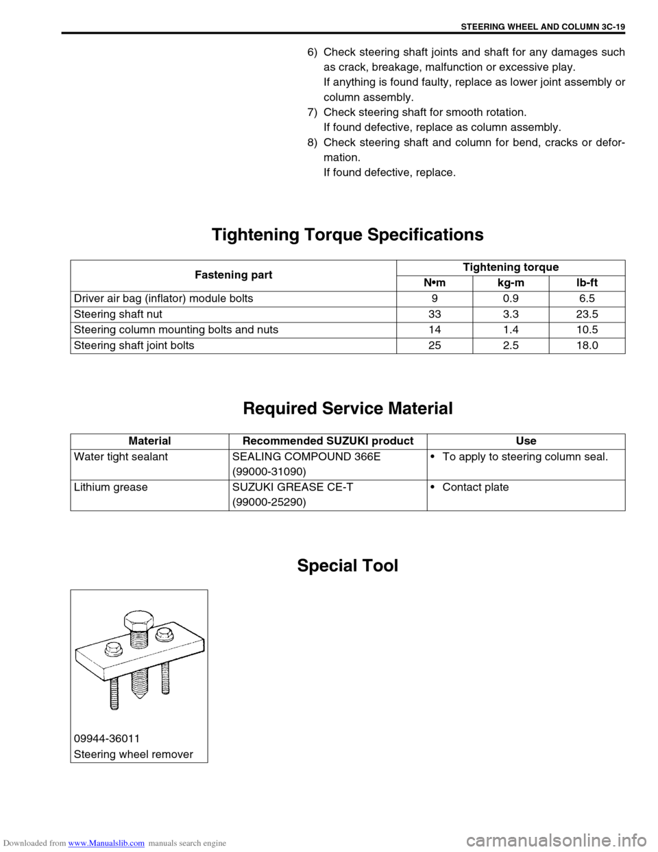
09944-36011
Steering wheel remover
Page 197 of 687

Downloaded from www.Manualslib.com manuals search engine 3D-24 FRONT SUSPENSION
11) Using hydraulic press (1) and special tool remove wheel
bearing (2).
Special tool
(A) : 09913-75520
12) Remove hub bolts from hub.
INSTALLATION
1) Insert new stud in hub hole. Rotate stud slowly to assure ser-
rations are aligned with those made by original bolt.
2) Using special tool, press-fit wheel bearing (3) until its end
contacts stepped surface of wheel hub (4).
Special tool
(A) : 09944-78210
3) Install bearing circlip.
4) Drive in wheel bearing oil seal (1) by using special tools.
Special tool
(B) : 09944-66010
(C) : 09924-74510
1. Oil hydraulic press
2. Hub bolt
CAUTION:
Press-fit wheel bearing (3) vertically to hub (4).
1. Oil hydraulic press
2. Steel plate
Page 198 of 687
Downloaded from www.Manualslib.com manuals search engine FRONT SUSPENSION 3D-25
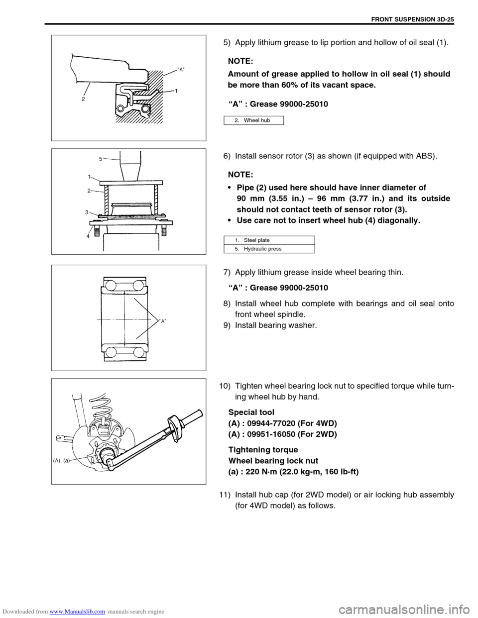
5) Apply lithium grease to lip portion and hollow of oil seal (1).
“A” : Grease 99000-25010
6) Install sensor rotor (3) as shown (if equipped with ABS).
7) Apply lithium grease inside wheel bearing thin.
“A” : Grease 99000-25010
8) Install wheel hub complete with bearings and oil seal onto
front wheel spindle.
9) Install bearing washer.
10) Tighten wheel bearing lock nut to specified torque while turn-
ing wheel hub by hand.
Special tool
(A) : 09944-77020 (For 4WD)
(A) : 09951-16050 (For 2WD)
Tightening torque
Wheel bearing lock nut
(a) : 220 N·m (22.0 kg-m, 160 lb-ft)
11) Install hub cap (for 2WD model) or air locking hub assembly
(for 4WD model) as follows. NOTE:
Amount of grease applied to hollow in oil seal (1) should
be more than 60% of its vacant space.
2. Wheel hub
NOTE:
Pipe (2) used here should have inner diameter of
90 mm (3.55 in.) – 96 mm (3.77 in.) and its outside
should not contact teeth of sensor rotor (3).
Use care not to insert wheel hub (4) diagonally.
1. Steel plate
5. Hydraulic press
Page 199 of 687
Downloaded from www.Manualslib.com manuals search engine 3D-26 FRONT SUSPENSION
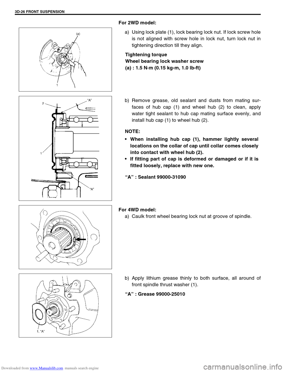
For 2WD model:
a) Using lock plate (1), lock bearing lock nut. If lock screw hole
is not aligned with screw hole in lock nut, turn lock nut in
tightening direction till they align.
Tightening torque
Wheel bearing lock washer screw
(a) : 1.5 N·m (0.15 kg-m, 1.0 lb-ft)
b) Remove grease, old sealant and dusts from mating sur-
faces of hub cap (1) and wheel hub (2) to clean, apply
water tight sealant to hub cap mating surface evenly, and
install hub cap (1) to wheel hub (2).
“A” : Sealant 99000-31090
For 4WD model:
a) Caulk front wheel bearing lock nut at groove of spindle.
b) Apply lithium grease thinly to both surface, all around of
front spindle thrust washer (1).
“A” : Grease 99000-25010
NOTE:
When installing hub cap (1), hammer lightly several
locations on the collar of cap until collar comes closely
into contact with wheel hub (2).
If fitting part of cap is deformed or damaged or if it is
fitted loosely, replace with new one.
Page 236 of 687
Downloaded from www.Manualslib.com manuals search engine REAR SUSPENSION 3E-17
16) Upon completion of all jobs, depress brake pedal with about
30 kg (66 lbs) load over ten times so as to obtain proper
drum-to shoe clearance.
Adjust parking brake cable. (For adjustment, refer to “Parking
Brake Check and Adjustment” in Section 5.)
17) Tighten parking brake lever cover screws.
18) Check to ensure that brake drum is free from dragging and
proper braking is obtained. Then remove vehicle from hoist
and perform brake test (foot brake and parking brake).
19) Check each installed part for oil leakage.
Rear Axle Shaft Inner Oil Seal
REMOVAL
1) Remove rear axle shaft. For details, refer to “Rear Axle Shaft
and Wheel Bearing” in this section.
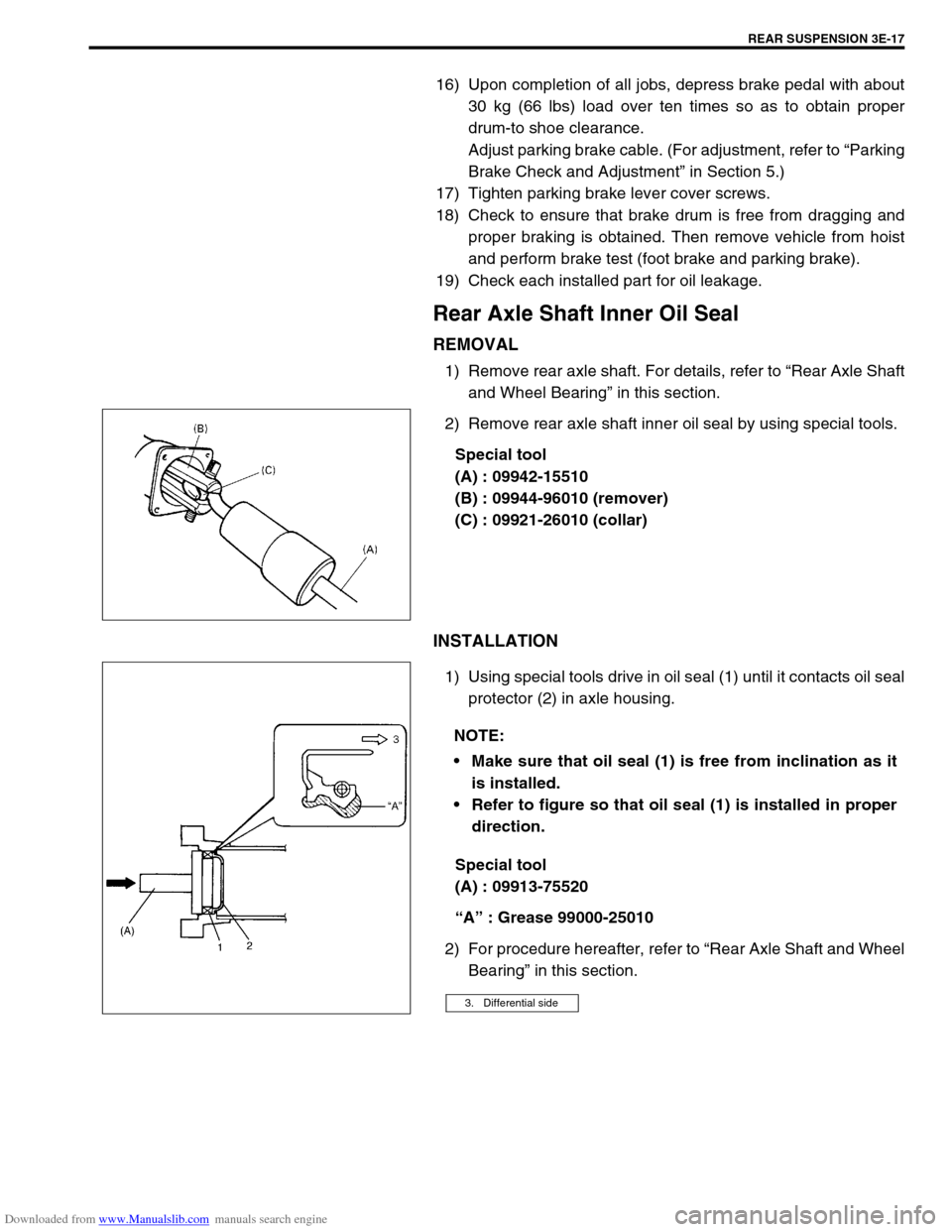
2) Remove rear axle shaft inner oil seal by using special tools.
Special tool
(A) : 09942-15510
(B) : 09944-96010 (remover)
(C) : 09921-26010 (collar)
INSTALLATION
1) Using special tools drive in oil seal (1) until it contacts oil seal
protector (2) in axle housing.
Special tool
(A) : 09913-75520
“A” : Grease 99000-25010
2) For procedure hereafter, refer to “Rear Axle Shaft and Wheel
Bearing” in this section.
NOTE:
Make sure that oil seal (1) is free from inclination as it
is installed.
Refer to figure so that oil seal (1) is installed in proper
direction.
3. Differential side