fuse SUZUKI JIMNY 2005 3.G Service Owner's Manual
[x] Cancel search | Manufacturer: SUZUKI, Model Year: 2005, Model line: JIMNY, Model: SUZUKI JIMNY 2005 3.GPages: 687, PDF Size: 13.38 MB
Page 449 of 687
Downloaded from www.Manualslib.com manuals search engine 6-92 ENGINE GENERAL INFORMATION AND DIAGNOSIS
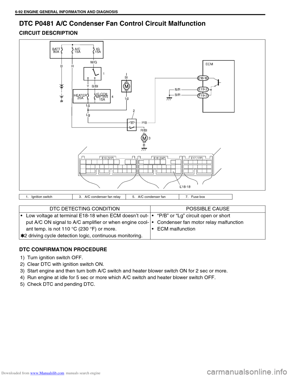
DTC P0481 A/C Condenser Fan Control Circuit Malfunction
CIRCUIT DESCRIPTION
DTC CONFIRMATION PROCEDURE
1) Turn ignition switch OFF.
2) Clear DTC with ignition switch ON.
3) Start engine and then turn both A/C switch and heater blower switch ON for 2 sec or more.
4) Run engine at idle for 5 sec or more which A/C switch and heater blower switch OFF.
5) Check DTC and pending DTC.
1. Ignition switch 3. A/C condenser fan relay 5. A/C condenser fan 7. Fuse box
DTC DETECTING CONDITION POSSIBLE CAUSE
Low voltage at terminal E18-18 when ECM doesn’t out-
put A/C ON signal to A/C amplifier or when engine cool-
ant temp. is not 110 °C (230 °F) or more.
✱
✱✱ ✱2 driving cycle detection logic, continuous monitoring.“P/B” or “Lg” circuit open or short
Condenser fan motor relay malfunction
ECM malfunction
Page 453 of 687
Downloaded from www.Manualslib.com manuals search engine 6-96 ENGINE GENERAL INFORMATION AND DIAGNOSIS
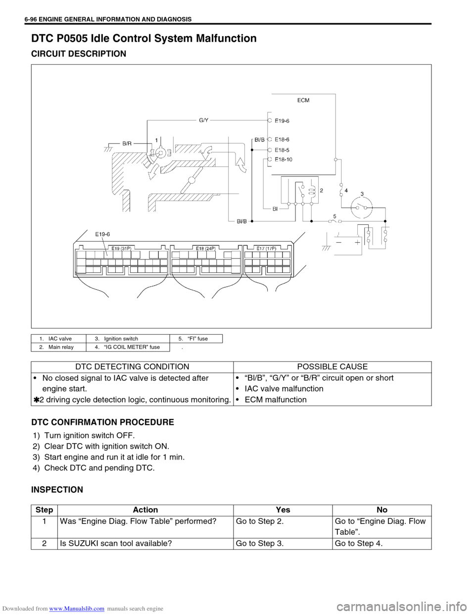
DTC P0505 Idle Control System Malfunction
CIRCUIT DESCRIPTION
DTC CONFIRMATION PROCEDURE
1) Turn ignition switch OFF.
2) Clear DTC with ignition switch ON.
3) Start engine and run it at idle for 1 min.
4) Check DTC and pending DTC.
INSPECTION
1. IAC valve 3. Ignition switch 5.“FI” fuse
2. Main relay 4.“IG COIL METER” fuse .
DTC DETECTING CONDITION POSSIBLE CAUSE
No closed signal to IAC valve is detected after
engine start.
✱
✱✱ ✱2 driving cycle detection logic, continuous monitoring.“Bl/B”, “G/Y” or “B/R” circuit open or short
IAC valve malfunction
ECM malfunction
Step Action Yes No
1Was “Engine Diag. Flow Table” performed? Go to Step 2. Go to “Engine Diag. Flow
Table”.
2 Is SUZUKI scan tool available? Go to Step 3. Go to Step 4.
Page 458 of 687
Downloaded from www.Manualslib.com manuals search engine ENGINE GENERAL INFORMATION AND DIAGNOSIS 6-101
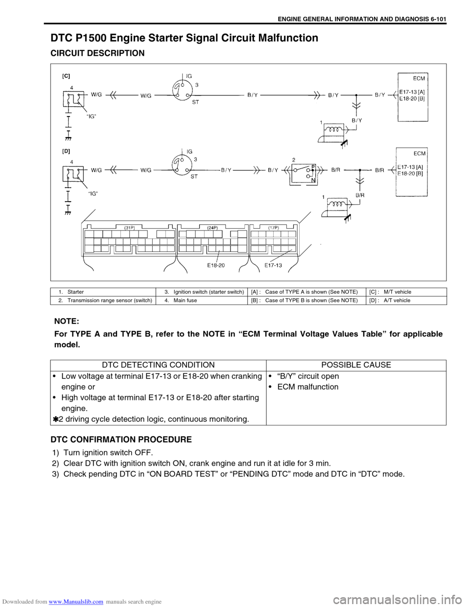
DTC P1500 Engine Starter Signal Circuit Malfunction
CIRCUIT DESCRIPTION
DTC CONFIRMATION PROCEDURE
1) Turn ignition switch OFF.
2) Clear DTC with ignition switch ON, crank engine and run it at idle for 3 min.
3) Check pending DTC in “ON BOARD TEST” or “PENDING DTC” mode and DTC in “DTC” mode.
1. Starter 3. Ignition switch (starter switch) [A] : Case of TYPE A is shown (See NOTE) [C] : M/T vehicle
2. Transmission range sensor (switch) 4. Main fuse [B] : Case of TYPE B is shown (See NOTE) [D] : A/T vehicle
NOTE:
For TYPE A and TYPE B, refer to the NOTE in “ECM Terminal Voltage Values Table” for applicable
model.
DTC DETECTING CONDITION POSSIBLE CAUSE
Low voltage at terminal E17-13 or E18-20 when cranking
engine or
High voltage at terminal E17-13 or E18-20 after starting
engine.
✱
✱✱ ✱2 driving cycle detection logic, continuous monitoring.“B/Y” circuit open
ECM malfunction
Page 460 of 687
Downloaded from www.Manualslib.com manuals search engine ENGINE GENERAL INFORMATION AND DIAGNOSIS 6-103
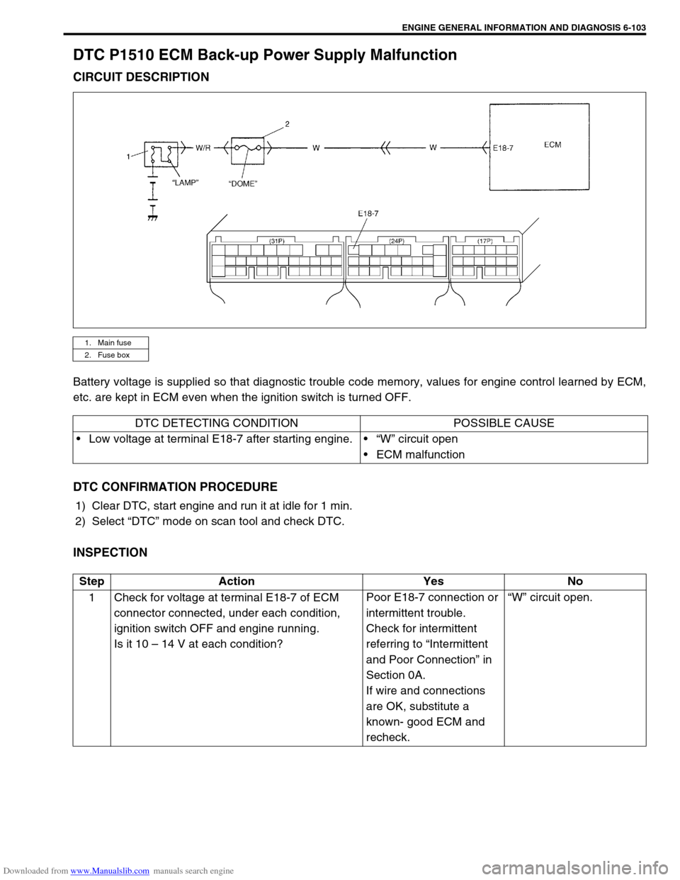
DTC P1510 ECM Back-up Power Supply Malfunction
CIRCUIT DESCRIPTION
Battery voltage is supplied so that diagnostic trouble code memory, values for engine control learned by ECM,
etc. are kept in ECM even when the ignition switch is turned OFF.
DTC CONFIRMATION PROCEDURE
1) Clear DTC, start engine and run it at idle for 1 min.
2) Select “DTC” mode on scan tool and check DTC.
INSPECTION
1. Main fuse
2. Fuse box
DTC DETECTING CONDITION POSSIBLE CAUSE
Low voltage at terminal E18-7 after starting engine.“W” circuit open
ECM malfunction
Step Action Yes No
1 Check for voltage at terminal E18-7 of ECM
connector connected, under each condition,
ignition switch OFF and engine running.
Is it 10 – 14 V at each condition?Poor E18-7 connection or
intermittent trouble.
Check for intermittent
referring to “Intermittent
and Poor Connection” in
Section 0A.
If wire and connections
are OK, substitute a
known- good ECM and
recheck.“W” circuit open.
Page 467 of 687
Downloaded from www.Manualslib.com manuals search engine 6-110 ENGINE GENERAL INFORMATION AND DIAGNOSIS
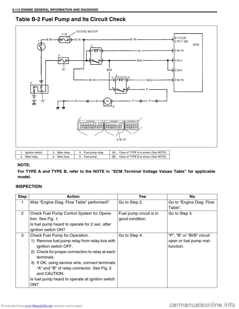
Table B-2 Fuel Pump and Its Circuit Check
INSPECTION
1. Ignition switch 3. Main relay 5. Fuel pump relay [A] : Case of TYPE A is shown (See NOTE)
2. Main relay 4. Main fuse 6. Fuel pump [B] : Case of TYPE B is shown (See NOTE)
NOTE:
For TYPE A and TYPE B, refer to the NOTE in “ECM Terminal Voltage Values Table” for applicable
model.
Step Action Yes No
1Was “Engine Diag. Flow Table” performed? Go to Step 2. Go to “Engine Diag. Flow
Table”.
2 Check Fuel Pump Control System for Opera-
tion. See Fig. 1.
Is fuel pump heard to operate for 2 sec. after
ignition switch ON?Fuel pump circuit is in
good condition.Go to Step 3.
3 Check Fuel Pump for Operation.
1) Remove fuel pump relay from relay box with
ignition switch OFF.
2) Check for proper connection to relay at each
terminals.
3) If OK, using service wire, connect terminals
“A” and “B” of relay connector. See Fig. 2
and CAUTION.
Is fuel pump heard to operate at ignition switch
ON?Go to Step 4.“P”, “B” or “Bl/B” circuit
open or fuel pump mal-
function.
Page 471 of 687
Downloaded from www.Manualslib.com manuals search engine 6-114 ENGINE GENERAL INFORMATION AND DIAGNOSIS
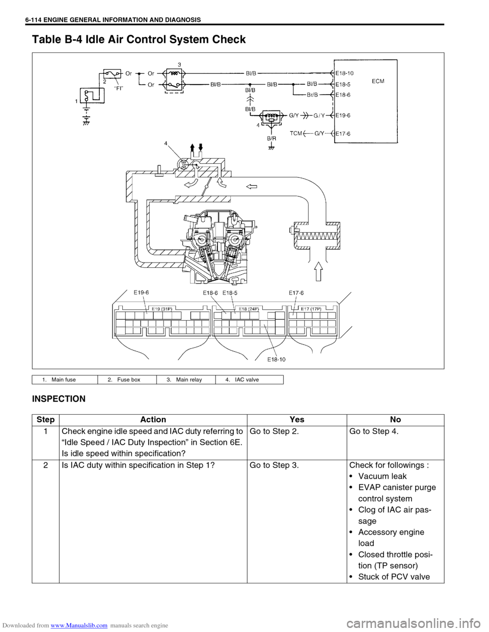
Table B-4 Idle Air Control System Check
INSPECTION
1. Main fuse 2. Fuse box 3. Main relay 4. IAC valve
Step Action Yes No
1 Check engine idle speed and IAC duty referring to
“Idle Speed / IAC Duty Inspection” in Section 6E.
Is idle speed within specification?Go to Step 2. Go to Step 4.
2 Is IAC duty within specification in Step 1? Go to Step 3. Check for followings :
Vacuum leak
EVAP canister purge
control system
Clog of IAC air pas-
sage
Accessory engine
load
Closed throttle posi-
tion (TP sensor)
Stuck of PCV valve
Page 652 of 687
Downloaded from www.Manualslib.com manuals search engine IGNITION SYSTEM (ELECTRONIC IGNITION SYSTEM 6F-3
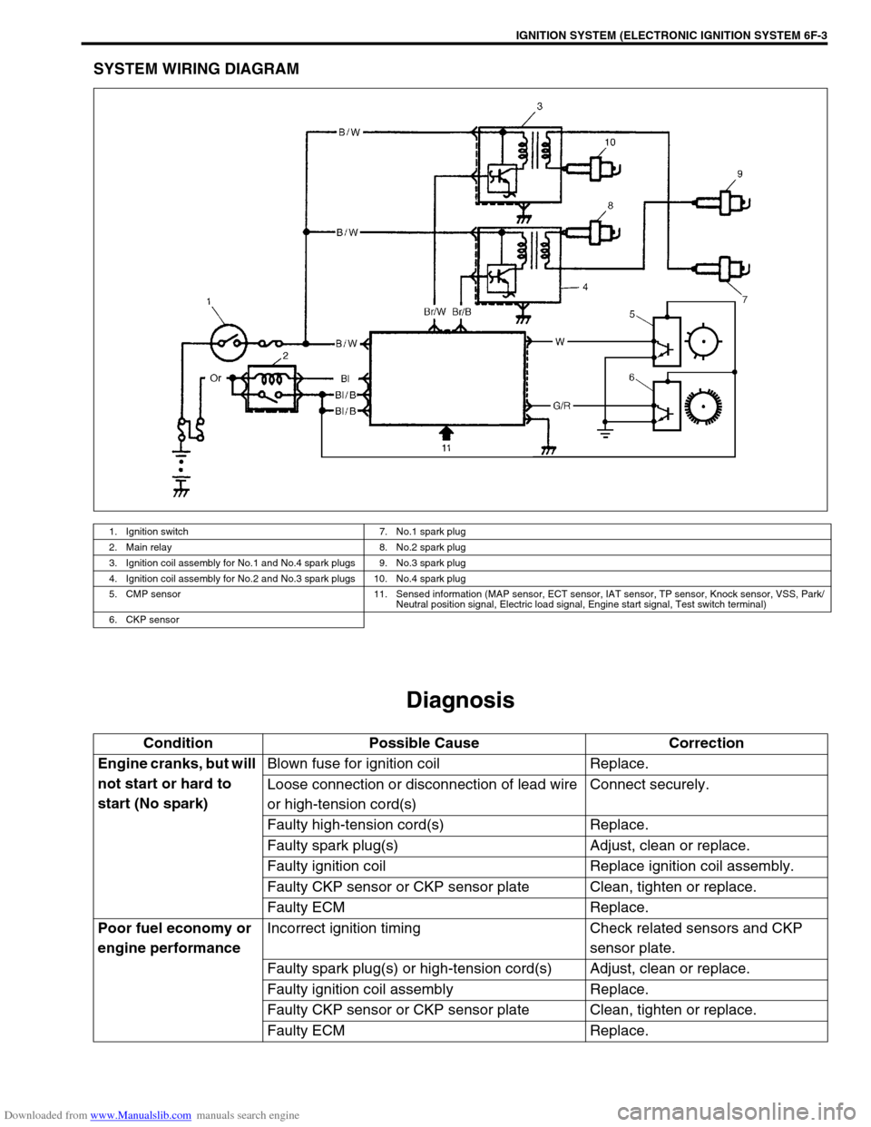
SYSTEM WIRING DIAGRAM
Diagnosis
1. Ignition switch 7. No.1 spark plug
2. Main relay 8. No.2 spark plug
3. Ignition coil assembly for No.1 and No.4 spark plugs 9. No.3 spark plug
4. Ignition coil assembly for No.2 and No.3 spark plugs 10. No.4 spark plug
5. CMP sensor 11. Sensed information (MAP sensor, ECT sensor, IAT sensor, TP sensor, Knock sensor, VSS, Park/
Neutral position signal, Electric load signal, Engine start signal, Test switch terminal)
6. CKP sensor
Condition Possible Cause Correction
Engine cranks, but will
not start or hard to
start (No spark)Blown fuse for ignition coil Replace.
Loose connection or disconnection of lead wire
or high-tension cord(s)Connect securely.
Faulty high-tension cord(s) Replace.
Faulty spark plug(s) Adjust, clean or replace.
Faulty ignition coil Replace ignition coil assembly.
Faulty CKP sensor or CKP sensor plate Clean, tighten or replace.
Faulty ECM Replace.
Poor fuel economy or
engine performanceIncorrect ignition timing Check related sensors and CKP
sensor plate.
Faulty spark plug(s) or high-tension cord(s) Adjust, clean or replace.
Faulty ignition coil assembly Replace.
Faulty CKP sensor or CKP sensor plate Clean, tighten or replace.
Faulty ECM Replace.
Page 662 of 687

Downloaded from www.Manualslib.com manuals search engine CRANKING SYSTEM 6G-3
Condition Possible Cause Correction
Motor not running
(No operating sound of
magnetic switch)Shift lever switch is not in P or N, or not adjusted
(A/T)Shift in P or N, or adjust switch.
Battery run down Recharge battery.
Battery voltage too low due to battery deteriora-
tionReplace battery.
Poor contact in battery terminal connection Retighten or replace.
Loose grounding cable connection Retighten.
Fuse set loose or blown off Tighten or replace.
Poor contacting action of ignition switch and mag-
netic switchReplace.
Lead wire coupler loose in place Retighten.
Open-circuit between ignition switch and magnetic
switchRepair.
Open-circuit in pull-in coil Replace magnetic switch.
Brushes are seating poorly or worn down Repair or replace.
Poor sliding of plunger and/or pinion Repair.
Motor not running
(Operating sound of
magnetic switch
heard)Battery run down Recharge battery.
Battery voltage too low due to battery deteriora-
tionReplace battery.
Loose battery cable connections Retighten.
Burnt main contact point, or poor contacting action
of magnetic switchReplace magnetic switch.
Brushes are seating poorly or worn down Repair or replace.
Weakened brush spring Replace.
Burnt commutator Replace armature.
Layer short-circuit of armature Replace.
Crankshaft rotation obstructed Repair.
Starting motor running
but too slow (small
torque) (If battery and
wiring are satisfac-
tory, inspect starting
motor)Insufficient contact of magnetic switch main con-
tactsReplace magnetic switch.
Layer short-circuit of armature Replace.
Disconnected, burnt or worn commutator Repair commutator or replace
armature.
Worn brushes Replace brush.
Weakened brush springs Replace spring.
Burnt or abnormally worn end bush Replace bush.
Starting motor run-
ning, but not cranking
engineWorn pinion tip Replace over-running clutch.
Poor sliding of over-running clutch Repair.
Over-running clutch slipping Replace over-running clutch.
Worn teeth of ring gear Replace flywheel (M/T) or drive
plate (A/T).
Noise
Abnormally worn bush Replace bush.
Worn pinion or worn teeth of ring gear Replace pinion or flywheel
(M/T) or drive plate (A/T).
Poor sliding of pinion (failure in return movement) Repair or replace.
Worn internal or planetary gear teeth Replace.
Lack of oil in each part Lubricate.
Page 663 of 687
Downloaded from www.Manualslib.com manuals search engine 6G-4 CRANKING SYSTEM
Performance Test
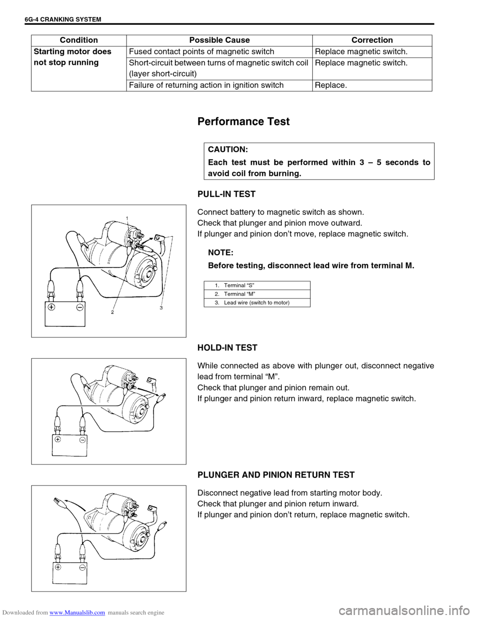
PULL-IN TEST
Connect battery to magnetic switch as shown.
Check that plunger and pinion move outward.
If plunger and pinion don’t move, replace magnetic switch.
HOLD-IN TEST
While connected as above with plunger out, disconnect negative
lead from terminal “M”.
Check that plunger and pinion remain out.
If plunger and pinion return inward, replace magnetic switch.
PLUNGER AND PINION RETURN TEST
Disconnect negative lead from starting motor body.
Check that plunger and pinion return inward.
If plunger and pinion don’t return, replace magnetic switch. Starting motor does
not stop runningFused contact points of magnetic switch Replace magnetic switch.
Short-circuit between turns of magnetic switch coil
(layer short-circuit)Replace magnetic switch.
Failure of returning action in ignition switch Replace.
CAUTION:
Each test must be performed within 3 – 5 seconds to
avoid coil from burning.
NOTE:
Before testing, disconnect lead wire from terminal M.
1. Terminal “S”
2. Terminal “M”
3. Lead wire (switch to motor)
Condition Possible Cause Correction
Page 674 of 687
Downloaded from www.Manualslib.com manuals search engine CHARGING SYSTEM 6H-7
How to use the temperature-corrected state-of-charge
graph
Suppose your S.G. reading is 1.28 and the battery temperature is
–5 °C (23 °F). Locate the intersection of the –5 °C line and the
1.28 S.G. line.
The intersection is within the “A” zone (shaded area in the graph)
and that means CHARGED STATE.
To know how much the battery is charged, draw a line parallel to
the zone demarcation line and extend it to the right till it meets
with the percentage scale. In the present example, the line meets
at about 85% point on the percentage scale. Therefore, the bat-
tery is charged up to the 85% level.
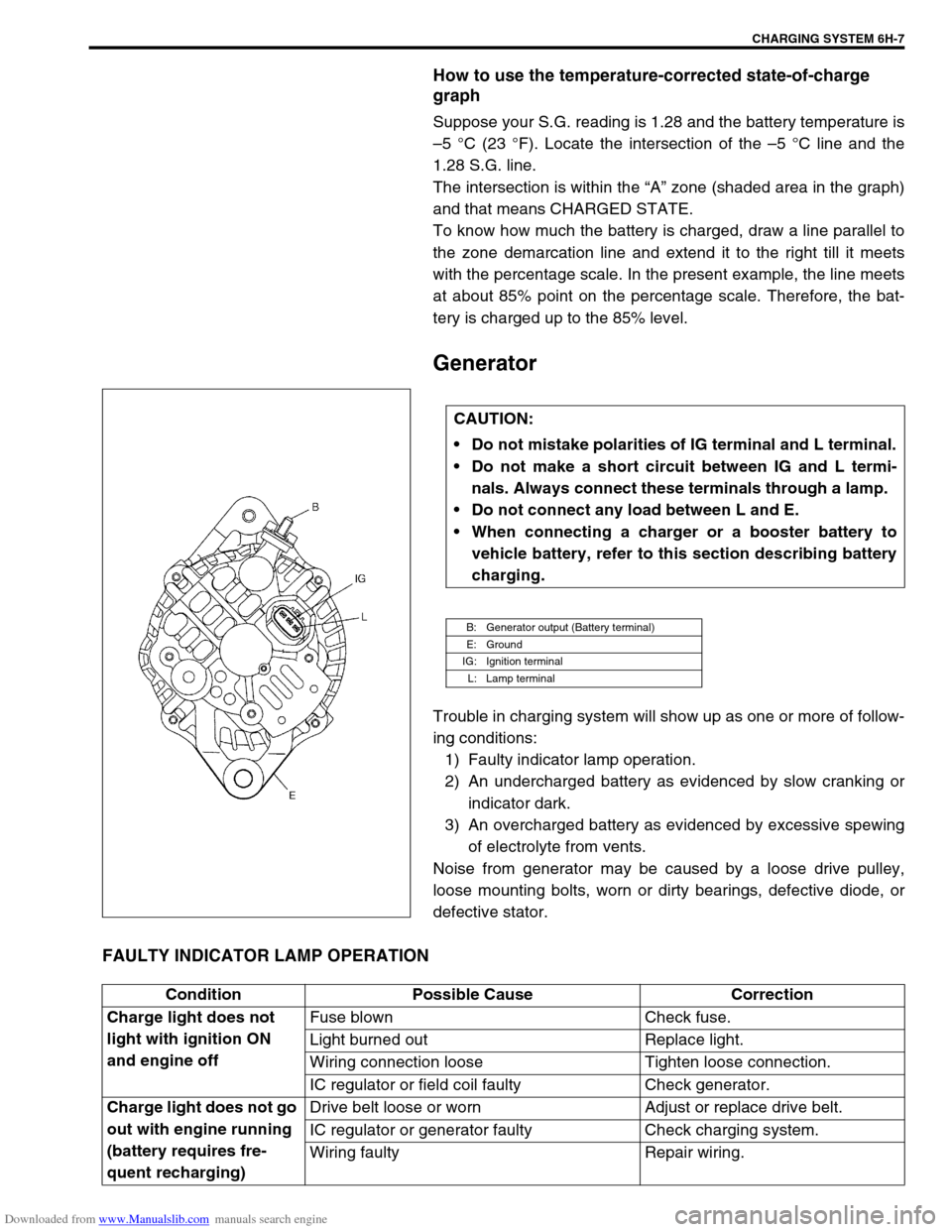
Generator
Trouble in charging system will show up as one or more of follow-
ing conditions:
1) Faulty indicator lamp operation.
2) An undercharged battery as evidenced by slow cranking or
indicator dark.
3) An overcharged battery as evidenced by excessive spewing
of electrolyte from vents.
Noise from generator may be caused by a loose drive pulley,
loose mounting bolts, worn or dirty bearings, defective diode, or
defective stator.
FAULTY INDICATOR LAMP OPERATION
CAUTION:
Do not mistake polarities of IG terminal and L terminal.
Do not make a short circuit between IG and L termi-
nals. Always connect these terminals through a lamp.
Do not connect any load between L and E.
When connecting a charger or a booster battery to
vehicle battery, refer to this section describing battery
charging.
B: Generator output (Battery terminal)
E: Ground
IG: Ignition terminal
L: Lamp terminal
Condition Possible Cause Correction
Charge light does not
light with ignition ON
and engine offFuse blown Check fuse.
Light burned out Replace light.
Wiring connection loose Tighten loose connection.
IC regulator or field coil faulty Check generator.
Charge light does not go
out with engine running
(battery requires fre-
quent recharging)Drive belt loose or worn Adjust or replace drive belt.
IC regulator or generator faulty Check charging system.
Wiring faulty Repair wiring.