fuse SUZUKI JIMNY 2005 3.G Service User Guide
[x] Cancel search | Manufacturer: SUZUKI, Model Year: 2005, Model line: JIMNY, Model: SUZUKI JIMNY 2005 3.GPages: 687, PDF Size: 13.38 MB
Page 337 of 687
Downloaded from www.Manualslib.com manuals search engine 5E-20 ANTILOCK BRAKE SYSTEM (ABS)
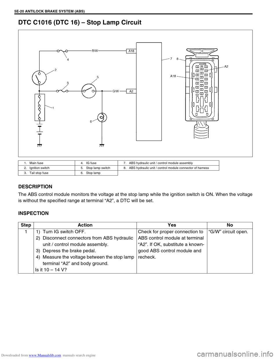
DTC C1016 (DTC 16) – Stop Lamp Circuit
DESCRIPTION
The ABS control module monitors the voltage at the stop lamp while the ignition switch is ON. When the voltage
is without the specified range at terminal “A2”, a DTC will be set.
INSPECTION
1. Main fuse 4. IG fuse 7. ABS hydraulic unit / control module assembly
2. Ignition switch 5. Stop lamp switch 8. ABS hydraulic unit / control module connector of harness
3. Tail stop fuse 6. Stop lamp
Step Action Yes No
1 1) Turn IG switch OFF.
2) Disconnect connectors from ABS hydraulic
unit / control module assembly.
3) Depress the brake pedal.
4) Measure the voltage between the stop lamp
terminal “A2” and body ground.
Is it 10 – 14 V?Check for proper connection to
ABS control module at terminal
“A2”. If OK, substitute a known-
good ABS control module and
recheck.“G/W” circuit open.
Page 342 of 687
Downloaded from www.Manualslib.com manuals search engine ANTILOCK BRAKE SYSTEM (ABS) 5E-25
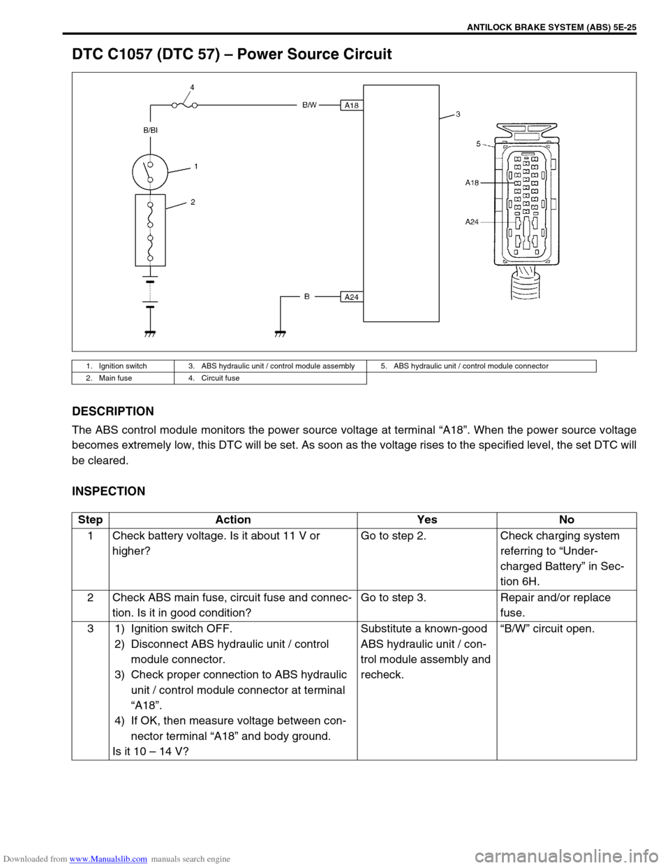
DTC C1057 (DTC 57) – Power Source Circuit
DESCRIPTION
The ABS control module monitors the power source voltage at terminal “A18”. When the power source voltage
becomes extremely low, this DTC will be set. As soon as the voltage rises to the specified level, the set DTC will
be cleared.
INSPECTION
1. Ignition switch 3. ABS hydraulic unit / control module assembly 5. ABS hydraulic unit / control module connector
2. Main fuse 4. Circuit fuse
Step Action Yes No
1 Check battery voltage. Is it about 11 V or
higher?Go to step 2. Check charging system
referring to “Under-
charged Battery” in Sec-
tion 6H.
2 Check ABS main fuse, circuit fuse and connec-
tion. Is it in good condition?Go to step 3. Repair and/or replace
fuse.
3 1) Ignition switch OFF.
2) Disconnect ABS hydraulic unit / control
module connector.
3) Check proper connection to ABS hydraulic
unit / control module connector at terminal
“A18”.
4) If OK, then measure voltage between con-
nector terminal “A18” and body ground.
Is it 10 – 14 V?Substitute a known-good
ABS hydraulic unit / con-
trol module assembly and
recheck.“B/W” circuit open.
Page 344 of 687
Downloaded from www.Manualslib.com manuals search engine ANTILOCK BRAKE SYSTEM (ABS) 5E-27
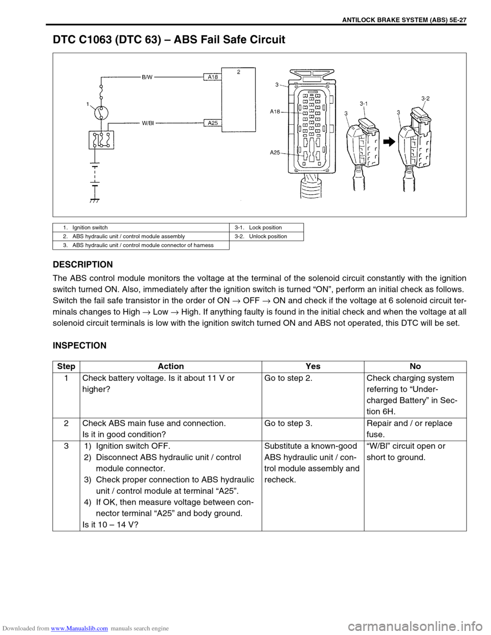
DTC C1063 (DTC 63) – ABS Fail Safe Circuit
DESCRIPTION
The ABS control module monitors the voltage at the terminal of the solenoid circuit constantly with the ignition
switch turned ON. Also, immediately after the ignition switch is turned “ON”, perform an initial check as follows.
Switch the fail safe transistor in the order of ON → OFF → ON and check if the voltage at 6 solenoid circuit ter-
minals changes to High → Low → High. If anything faulty is found in the initial check and when the voltage at all
solenoid circuit terminals is low with the ignition switch turned ON and ABS not operated, this DTC will be set.
INSPECTION
1. Ignition switch 3-1. Lock position
2. ABS hydraulic unit / control module assembly 3-2. Unlock position
3. ABS hydraulic unit / control module connector of harness
Step Action Yes No
1 Check battery voltage. Is it about 11 V or
higher?Go to step 2. Check charging system
referring to “Under-
charged Battery” in Sec-
tion 6H.
2 Check ABS main fuse and connection.
Is it in good condition?Go to step 3. Repair and / or replace
fuse.
3 1) Ignition switch OFF.
2) Disconnect ABS hydraulic unit / control
module connector.
3) Check proper connection to ABS hydraulic
unit / control module at terminal “A25”.
4) If OK, then measure voltage between con-
nector terminal “A25” and body ground.
Is it 10 – 14 V?Substitute a known-good
ABS hydraulic unit / con-
trol module assembly and
recheck.“W/Bl” circuit open or
short to ground.
Page 346 of 687
Downloaded from www.Manualslib.com manuals search engine ANTILOCK BRAKE SYSTEM (ABS) 5E-29
On-Vehicle Service
Precaution
When connectors are connected to ABS hydraulic unit / control
module assembly, do not disconnect connectors of sensors, fuse
etc. and turn ignition switch ON. Then DTC will be set in ABS con-
trol module.
ABS Hydraulic Unit Operation Check
1) Check that basic brake system other than ABS is in good
condition.
2) Check that battery voltage is 11 V or higher.
3) With ABS warning lamp, check that no abnormality is
detected in ABS. Refer to “Diagnostic Trouble Code (DTC)
Check” in this section.
4) Lift up vehicle.
5) Set transmission to neutral and release parking brake.
6) Turn each wheel gradually by hand to check if brake drag-
ging occurs. If it does, correct.
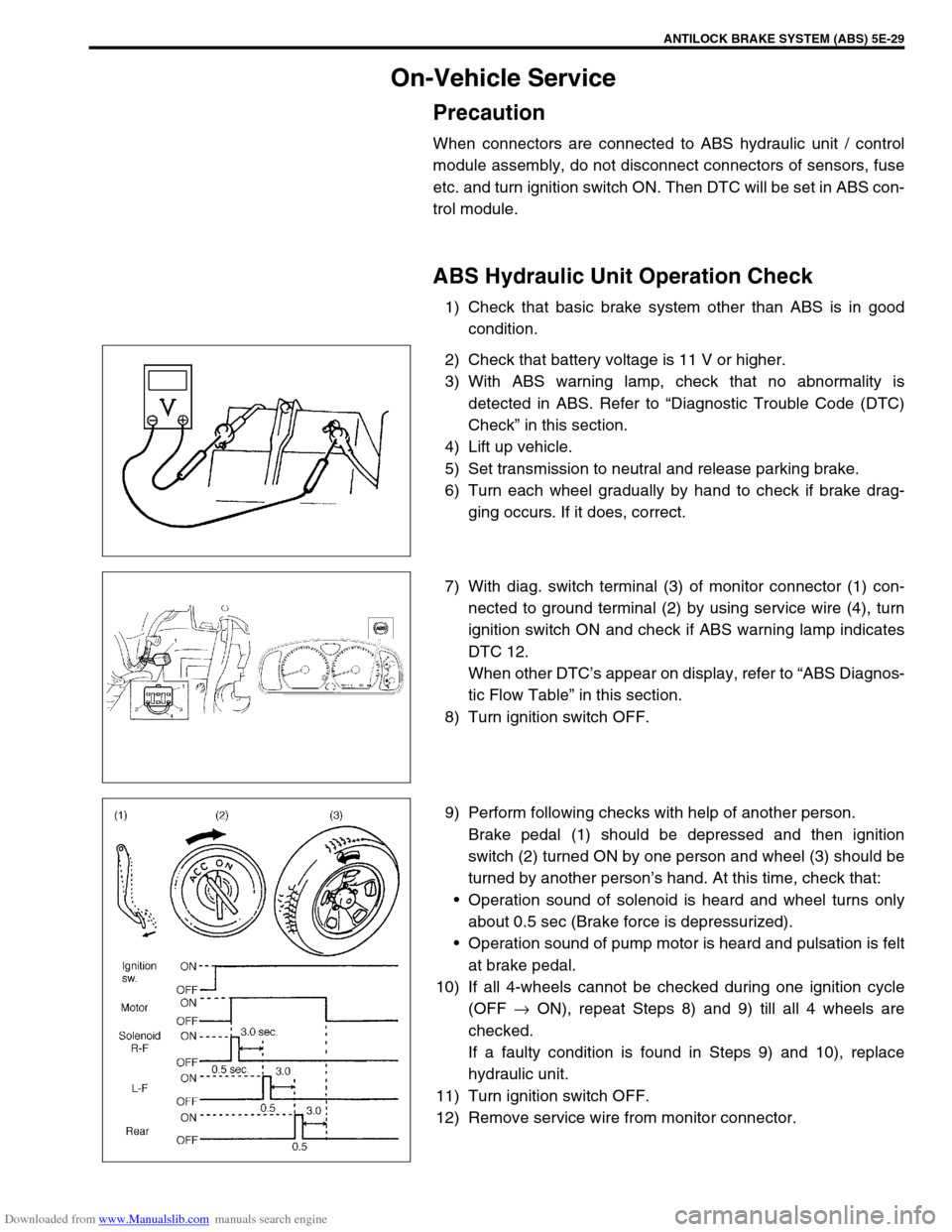
7) With diag. switch terminal (3) of monitor connector (1) con-
nected to ground terminal (2) by using service wire (4), turn
ignition switch ON and check if ABS warning lamp indicates
DTC 12.
When other DTC’s appear on display, refer to “ABS Diagnos-
tic Flow Table” in this section.
8) Turn ignition switch OFF.
9) Perform following checks with help of another person.
Brake pedal (1) should be depressed and then ignition
switch (2) turned ON by one person and wheel (3) should be
turned by another person’s hand. At this time, check that:
Operation sound of solenoid is heard and wheel turns only
about 0.5 sec (Brake force is depressurized).
Operation sound of pump motor is heard and pulsation is felt
at brake pedal.
10) If all 4-wheels cannot be checked during one ignition cycle
(OFF → ON), repeat Steps 8) and 9) till all 4 wheels are
checked.
If a faulty condition is found in Steps 9) and 10), replace
hydraulic unit.
11) Turn ignition switch OFF.
12) Remove service wire from monitor connector.
Page 367 of 687

Downloaded from www.Manualslib.com manuals search engine 6-10 ENGINE GENERAL INFORMATION AND DIAGNOSIS
Precaution in Diagnosing Trouble
Don’t disconnect couplers from ECM, battery cable at battery, ECM ground wire harness from engine or
main fuse before confirming diagnostic information (DTC, freeze frame data, etc.) stored in ECM memory.
Such disconnection will erase memorized information in ECM memory.
Diagnostic information stored in ECM memory can be cleared as well as checked by using SUZUKI scan
tool or generic scan tool. Before using scan tool, read its Operator’s (Instruction) Manual carefully to have
good understanding as to what functions are available and how to use it.
Priorities for diagnosing troubles (Vehicle with Immobilizer indicator lamp).
If multiple diagnostic trouble codes (DTCs) are stored, proceed to the flow table of the DTC which has
detected earliest in the order and follow the instruction in that table.
If no instructions are given, troubleshoot diagnostic trouble codes according to the following priorities.
–Diagnostic trouble codes (DTCs) other than DTC P0171/P0172 (Fuel system too lean / too rich), DTC
P0300/P0301/P0302/P0303/P0304 (Misfire detected) and DTC P0400 (EGR flow malfunction)
–DTC P0171/P0172 (Fuel system too lean / too rich) and DTC P0400 (EGR flow malfunction)
–DTC P0300/P0301/P0302/P0303/P0304 (Misfire detected)
Be sure to read “Precautions for Electrical Circuit Service” in Section 0A before inspection and observe what
is written there.
ECM Replacement
When substituting a known-good ECM, check for following conditions. Neglecting this check may cause
damage to a known-good ECM.
–Resistance value of all relays, actuators is as specified respectively.
–MAP sensor and TP sensor are in good condition and none of power circuits of these sensors is shorted
to ground.AMBIENT TEMPERATURE TIME TO CUT POWER TO
ECM
Over 0 °C (32 °F) 60 sec. or longer
Under 0 °C (32 °F)Not specifiable.
Select a place with higher than
0 °C (32 °F) temperature.
Page 372 of 687

Downloaded from www.Manualslib.com manuals search engine ENGINE GENERAL INFORMATION AND DIAGNOSIS 6-15
4) After completing the check, turn the ignition switch OFF posi-
tion and disconnect service wire from monitor coupler.
Diagnostic trouble code (DTC) clearance
[Using SUZUKI Scan Tool]
1) Connect SUZUKI scan tool to data link connector in the
same manner as when making this connection for DTC
check.
2) Turn ignition switch ON.
3) Erase DTC and pending DTC according to instructions dis-
played on scan tool. Refer to scan tool operator’s manual for
further details.
4) After completing the clearance, turn ignition switch off and
disconnect scan tool from data link connector.
[Without Using SUZUKI Scan Tool]
1) Turn the ignition switch OFF position.
2) Disconnect battery negative cable for specified time below to
erase diagnostic trouble code stored in ECM memory and
reconnect it.
Time required to erase DTC NOTE:
If abnormality or malfunction lies in two or more areas,
malfunction indicator lamp indicates applicable codes
three times each.
And flashing of these codes is repeated as long as
diagnosis terminal is grounded and ignition switch is
held at ON position.
Take a note of diagnostic trouble code indicated first.
NOTE:
DTC and freeze frame data stored in ECM memory are
also cleared in following cases. Be careful not to clear
them before keeping their record.
When power to ECM is cut off (by disconnecting bat-
tery cable, removing fuse or disconnecting ECM con-
nectors)
When the same malfunction (DTC) is not detected
again during 40 engine warm-up cycles.
Ambient temperature Time to cut power to ECM
Over 0 °C (32 °F) 30 sec. or longer
Under 0 °C (32 °F)Not specifiable.
Select a place with higher than
0 °C (32 °F) temperature.
Page 377 of 687

Downloaded from www.Manualslib.com manuals search engine 6-20 ENGINE GENERAL INFORMATION AND DIAGNOSIS
Visual inspection
Visually check following parts and systems.
INSPECTION ITEM REFERRING SECTION
Engine oil – level, leakage Section 0B
Engine coolant – level, leakage Section 0B
Fuel – level, leakage Section 0B
A/T fluid – level, leakage Section 0B
Air cleaner element – dirt, clogging Section 0B
Battery – fluid level, corrosion of terminal
Water pump belt – tension, damage Section 0B
Throttle cable – play, installation
Section 6E Vacuum hoses of air intake system – disconnection, looseness,
deterioration, bend
Connectors of electric wire harness – disconnection, friction
Fuses – burning Section 8
Parts – installation, bolt – looseness
Parts – deformation
Other parts that can be checked visually
Also check following items at engine start, if possible
Malfunction indicator lamp – operation Section 6
Charge warning lamp – operation Section 6H
Engine oil pressure warning lamp – operation Section 8 (Section 6 for pressure check)
Engine coolant temp. meter – operation Section 8
Fuel level meter – operation Section 8
Tachometer, if equipped – operation
Abnormal air being inhaled from air intake system
Exhaust system – leakage of exhaust gas, noise
Other parts that can be checked visually
Page 400 of 687
Downloaded from www.Manualslib.com manuals search engine ENGINE GENERAL INFORMATION AND DIAGNOSIS 6-43
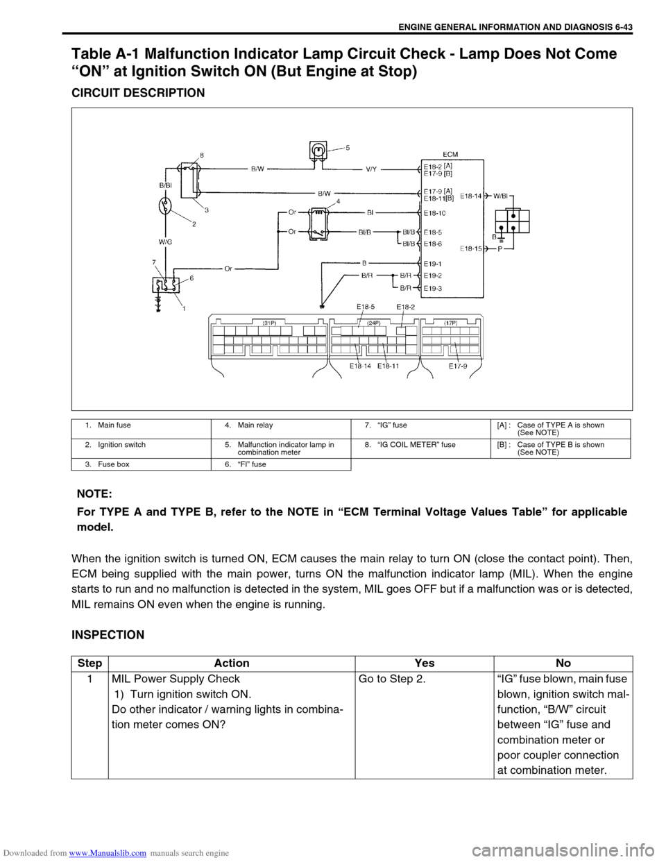
Table A-1 Malfunction Indicator Lamp Circuit Check - Lamp Does Not Come
“ON” at Ignition Switch ON (But Engine at Stop)
CIRCUIT DESCRIPTION
When the ignition switch is turned ON, ECM causes the main relay to turn ON (close the contact point). Then,
ECM being supplied with the main power, turns ON the malfunction indicator lamp (MIL). When the engine
starts to run and no malfunction is detected in the system, MIL goes OFF but if a malfunction was or is detected,
MIL remains ON even when the engine is running.
INSPECTION
1. Main fuse 4. Main relay 7.“IG” fuse [A] : Case of TYPE A is shown
(See NOTE)
2. Ignition switch 5. Malfunction indicator lamp in
combination meter8.“IG COIL METER” fuse [B] : Case of TYPE B is shown
(See NOTE)
3. Fuse box 6.“FI” fuse
NOTE:
For TYPE A and TYPE B, refer to the NOTE in “ECM Terminal Voltage Values Table” for applicable
model.
Step Action Yes No
1 MIL Power Supply Check
1) Turn ignition switch ON.
Do other indicator / warning lights in combina-
tion meter comes ON?Go to Step 2.“IG” fuse blown, main fuse
blown, ignition switch mal-
function, “B/W” circuit
between “IG” fuse and
combination meter or
poor coupler connection
at combination meter.
Page 403 of 687
Downloaded from www.Manualslib.com manuals search engine 6-46 ENGINE GENERAL INFORMATION AND DIAGNOSIS
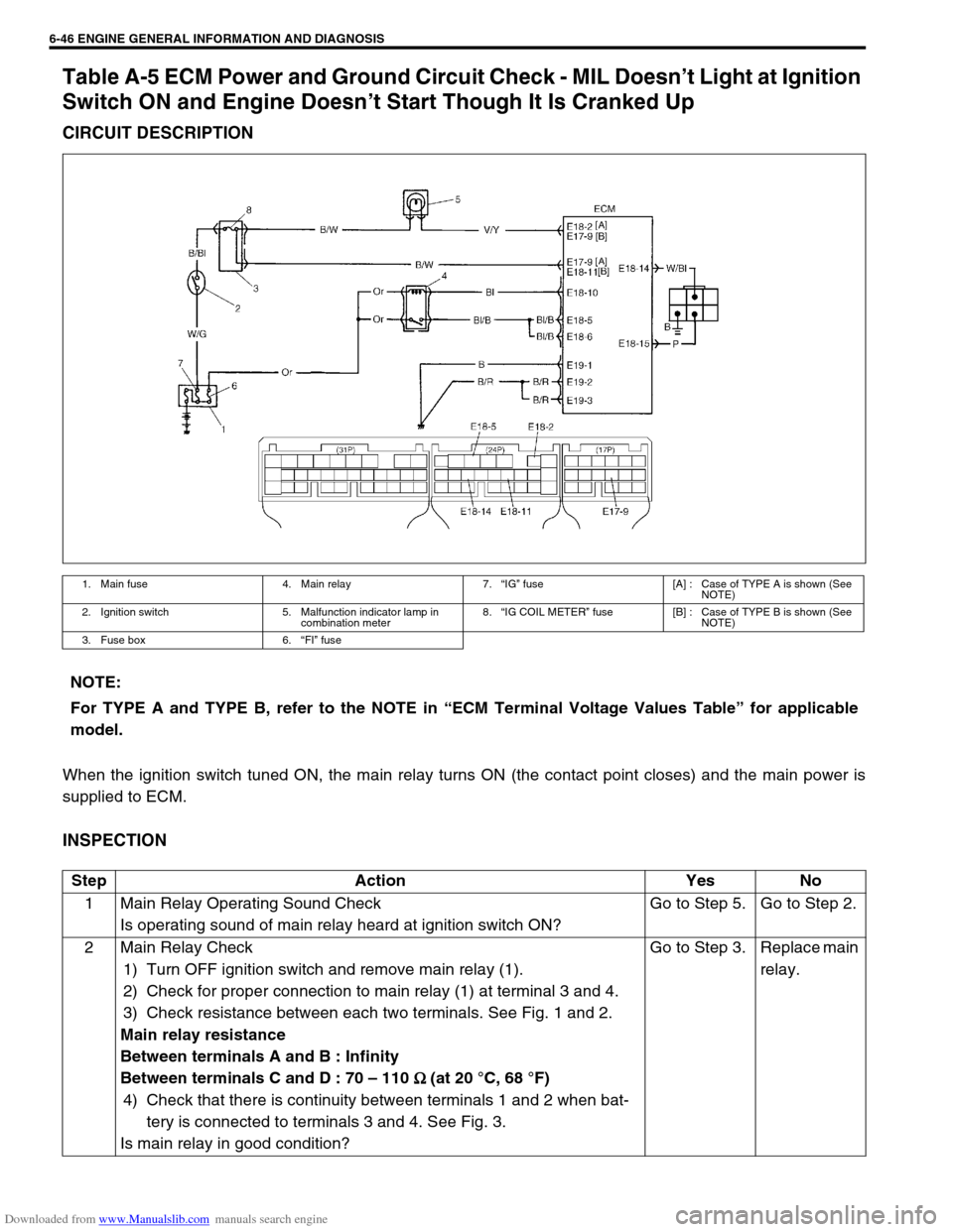
Table A-5 ECM Power and Ground Circuit Check - MIL Doesn’t Light at Ignition
Switch ON and Engine Doesn’t Start Though It Is Cranked Up
CIRCUIT DESCRIPTION
When the ignition switch tuned ON, the main relay turns ON (the contact point closes) and the main power is
supplied to ECM.
INSPECTION
1. Main fuse 4. Main relay 7.“IG” fuse [A] : Case of TYPE A is shown (See
NOTE)
2. Ignition switch 5. Malfunction indicator lamp in
combination meter8.“IG COIL METER” fuse [B] : Case of TYPE B is shown (See
NOTE)
3. Fuse box 6.“FI” fuse
NOTE:
For TYPE A and TYPE B, refer to the NOTE in “ECM Terminal Voltage Values Table” for applicable
model.
Step Action Yes No
1 Main Relay Operating Sound Check
Is operating sound of main relay heard at ignition switch ON?Go to Step 5. Go to Step 2.
2 Main Relay Check
1) Turn OFF ignition switch and remove main relay (1).
2) Check for proper connection to main relay (1) at terminal 3 and 4.
3) Check resistance between each two terminals. See Fig. 1 and 2.
Main relay resistance
Between terminals A and B : Infinity
Between terminals C and D : 70 – 110
Ω
Ω Ω Ω (at 20 °C, 68 °F)
4) Check that there is continuity between terminals 1 and 2 when bat-
tery is connected to terminals 3 and 4. See Fig. 3.
Is main relay in good condition?Go to Step 3. Replace main
relay.
Page 404 of 687
![SUZUKI JIMNY 2005 3.G Service User Guide Downloaded from www.Manualslib.com manuals search engine ENGINE GENERAL INFORMATION AND DIAGNOSIS 6-47
[A] Fig. 1 for Step 2 and 3 / [B] Fig. 2 for Step 2 / [C] Fig. 3 for Step 23 Fuse Check
Is main � SUZUKI JIMNY 2005 3.G Service User Guide Downloaded from www.Manualslib.com manuals search engine ENGINE GENERAL INFORMATION AND DIAGNOSIS 6-47
[A] Fig. 1 for Step 2 and 3 / [B] Fig. 2 for Step 2 / [C] Fig. 3 for Step 23 Fuse Check
Is main �](/img/20/7588/w960_7588-403.png)
Downloaded from www.Manualslib.com manuals search engine ENGINE GENERAL INFORMATION AND DIAGNOSIS 6-47
[A] Fig. 1 for Step 2 and 3 / [B] Fig. 2 for Step 2 / [C] Fig. 3 for Step 23 Fuse Check
Is main “FI” fuse in good condition? See Fig. 1.Go to Step 4. Check for
short in cir-
cuits con-
nected to this
fuse.
4 ECM Power Circuit Check
1) Turn OFF ignition switch, disconnect connectors from ECM and
install main relay.
2) Check for proper connection to ECM at terminals E17-9 (Case of
TYPE A) (See NOTE) or E18-11 (Case of TYPE B) (See NOTE),
E18-10, E18-5 and E18-6.
3) If OK, then measure voltage between terminal E18-10 and ground,
E17-9 (Case of TYPE A) (See NOTE) or E18-11 (Case of TYPE B)
(See NOTE) and ground with ignition switch ON.
Is each voltage 10 – 14 V?Go to Step 5.“B/W”, “Or” or
“Bl/B” circuit
open.
5 ECM Power Circuit Check
1) Using service wire, ground terminal E18-10 and measure voltage
between terminal E18-5 and ground at ignition switch ON.
Is it 10 – 14 V?Check
ground cir-
cuits “B” and
“B/R” for
open.
If OK, then
substitute a
known-good
ECM and
recheck.Go to Step 6.
6 Is operating sound of main relay heard in Step 1? Go to Step 7.“Bl/B” or “B/
R” wire open.
7 Main Relay Check
1) Check main relay according to procedure in Step 2.
Is main relay in good condition?“Or” or “Bl/B”
wire open.Replace main
relay. Step Action Yes No
2.“F1” fuse