check engine SUZUKI JIMNY 2005 3.G Service Workshop Manual
[x] Cancel search | Manufacturer: SUZUKI, Model Year: 2005, Model line: JIMNY, Model: SUZUKI JIMNY 2005 3.GPages: 687, PDF Size: 13.38 MB
Page 565 of 687

Downloaded from www.Manualslib.com manuals search engine 6A1-84 ENGINE MECHANICAL (M13 ENGINE)
5) Remove bearing caps and using scale (1) on gauging plastic
(2) envelop, measure gauging plastic width at its widest
point. If clearance exceeds its limit, replace bearing. Always
replace both upper and lower inserts as a unit.
A new standard bearing may produce proper clearance. If
not, it will be necessary to regrind crankshaft journal for use
of 0.25 mm undersize bearing.
After selecting new bearing, recheck clearance.
Main bearing clearance
Standard : 0.025 – 0.045 mm (0.0010 – 0.0018 in.)
Limit : 0.065 mm (0.0026 in.)
Selection of main bearings
STANDARD BEARING:
If bearing is in malcondition, or bearing clearance is out of specifi-
cation, select a new standard bearing according to the following
procedure and install it.
1) First check journal diameter. As shown in figure, crank web
No.2 has stamped numbers.
Three kinds of numbers (“1”, “2” and “3”) represent the fol-
lowing journal diameters.
Stamped numbers on crank web No.2 represent journal
diameters marked with an arrow in figure respectively.
For example, stamped number “1” indicates that correspond-
ing journal diameter is 44.994 – 45.000 mm (1.7714 –
1.7717 in.).
Crankshaft journal diameter NOTE:
After checking the bearing clearance, check for thread
deformation of each bearing cap No.1 bolt according to
previous mentioned Step 4) once again.
Stamped numbers Journal diameter
144.994 – 45.000 mm
(1.7714 – 1.7717 in.)
244.988 – 44.994 mm
(1.7712 – 1.7714 in.)
344.982 – 44.988 mm
(1.7709 – 1.7712 in.)
Page 566 of 687

Downloaded from www.Manualslib.com manuals search engine ENGINE MECHANICAL (M13 ENGINE) 6A1-85
2) Next, check bearing cap bore diameter without bearing. On
mating surface of cylinder block, five alphabets are stamped
as shown in figure.
Three kinds of alphabets (“A”, “B” and “C”) represent the fol-
lowing cap bore diameters.
Stamped alphabets on cylinder block represent bearing cap
bore diameter marked with an arrow in figure respectively.
For example, stamped “A” indicates that corresponding
bearing cap bore diameter is 49.000 – 49.006 mm (1.9291 –
1.9294 in.).
Crankshaft bearing cap bore
3) There are five kinds of standard bearings differing in thick-
ness. To distinguish them, they are painted in the following
colors at the center of bearings.
Each color indicates the following thickness.
Standard size of crankshaft main bearingStamped alphabetBearing cap bore diameter
(without bearing)
A49.000 – 49.006 mm
(1.9291 – 1.9294 in.)
B49.006 – 49.012 mm
(1.9294 – 1.9296 in.)
C49.012 – 49.018 mm
(1.9296 – 1.9298 in.)
Color painted Bearing thickness
Pink1.990 – 1.994 mm
(0.0783 – 0.0785 in.)
Purple1.993 – 1.997 mm
(0.0785 – 0.0786 in.)
Brown1.996 – 2.000 mm
(0.0786 – 0.0787 in.)
Green1.999 – 2.003 mm
(0.0787 – 0.0789 in.)
Black2.002 – 2.006 mm
(0.0788 – 0.0790 in.)
1. Paint
Page 567 of 687

Downloaded from www.Manualslib.com manuals search engine 6A1-86 ENGINE MECHANICAL (M13 ENGINE)
4) From number stamped on crank web No.2 and alphabets
stamped on cylinder block, determine new standard bearing
to be installed to journal, by referring to table shown below.
For example, if number stamped on crank web No.2 is “1”
and alphabet stamped on cylinder block is “B”, install a new
standard bearing painted in “Purple” to its journal.
Specification of standard crankshaft main bearing
5) Using scale (1) on gauging plastic (2), check bearing clear-
ance with newly selected standard bearing.
If clearance still exceeds its limit, use next thicker bearing
and recheck clearance.
6) When replacing crankshaft or cylinder block due to any rea-
son, select new standard bearings to be installed by referring
to number stamped on new crankshaft or alphabets stamped
on new cylinder block.
UNDERSIZE BEARING (0.25 mm):
0.25 mm undersize bearing is available, in five kinds varying
in thickness.
To distinguish them, each bearing is painted in the following
colors at the center of bearing.
Each color represents the following thickness.
Undersize of crankshaft main bearingNumber stamped on crank web
No.2 (Journal diameter)
123
Alphabet
stamped on
cylinder block
(Cap bore dia.)APink Purple Brown
B Purple Brown Green
C Brown Green Black
New standard bearing to be
installed.
Color painted Bearing thickness
Red and Pink2.115 – 2.119 mm
(0.0833 – 0.0834 in.)
Red and Purple2.118 – 2.122 mm
(0.0834 – 0.0835 in.)
Red and Brown2.121 – 2.125 mm
(0.0835 – 0.0837 in.)
Red and Green2.124 – 2.128 mm
(0.0836 – 0.0838 in.)
Red and Black2.127 – 2.131 mm
(0.0837 – 0.0839 in.)
1. Paint
Page 568 of 687

Downloaded from www.Manualslib.com manuals search engine ENGINE MECHANICAL (M13 ENGINE) 6A1-87
If necessary, regrind crankshaft journal and select undersize
bearing to use with it as follows.
a) Regrind journal to the following finished diameter.
Finished diameter
44.732 – 44.750 mm (1.7611 – 1.7618 in.)
1) Using micrometer, measure reground journal diameter.
Measurement should be taken in two directions perpendicu-
lar to each other in order to check for out-of-round.
2) Using journal diameter measured above and alphabets
stamped on cylinder block, select an undersize bearing by
referring to table given below.
Check bearing clearance with newly selected undersize
bearing.
Specification of undersize crankshaft main bearing
Rear Oil Seal
Carefully inspect oil seal (1) for wear or damage.
If its lip is worn or damaged, replace it.
For oil seal installation, press-fit rear oil seal (1) to oil seal hous-
ing (2) by using special tool as shown in the figure.
Special tool
(A) : 09911-97820
Crank rear oil seal installing position
“a” : 3 mm (0.12 in.)
Measured journal diameter
44.744 – 44.750 mm
(1.7616 – 1.7618 in.)44.738 – 44.744 mm
(1.7613 – 1.7616 in.)44.732 – 44.738 mm
(1.7611 – 1.7613 in.)
Alphabets stamped
on cylinder blockA Red and Pink Red and Purple Red and Brown
B Red and Purple Red and Brown Red and Green
C Red and Brown Red and Green Red and Black
Undersize bearing to be installed
Page 569 of 687
Downloaded from www.Manualslib.com manuals search engine 6A1-88 ENGINE MECHANICAL (M13 ENGINE)
Flywheel
If ring gear is damaged, cracked or worn, replace flywheel.
If the surface contacting clutch disc is damaged, or exces-
sively worn, replace flywheel.
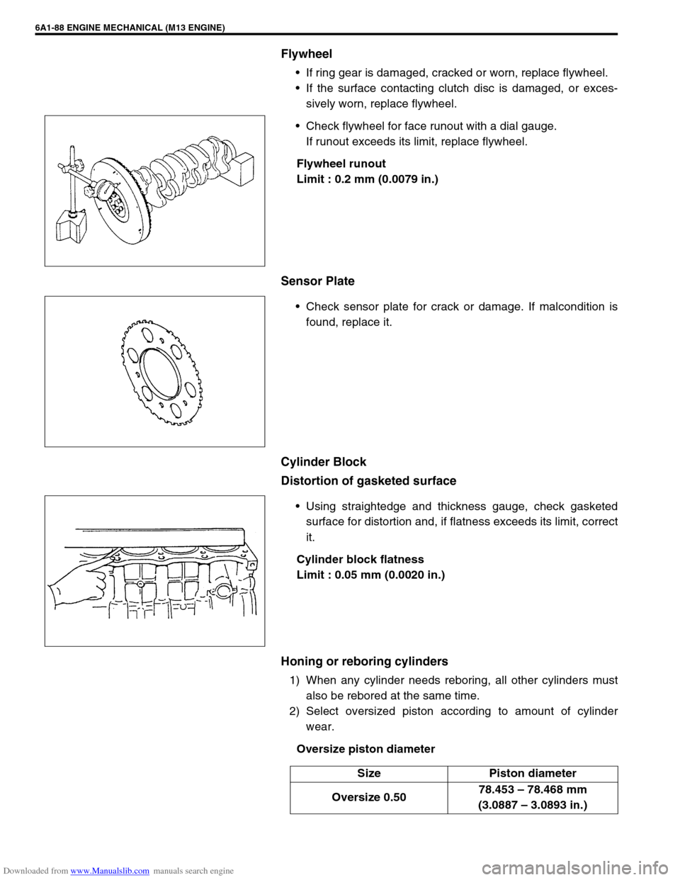
Check flywheel for face runout with a dial gauge.
If runout exceeds its limit, replace flywheel.
Flywheel runout
Limit : 0.2 mm (0.0079 in.)
Sensor Plate
Check sensor plate for crack or damage. If malcondition is
found, replace it.
Cylinder Block
Distortion of gasketed surface
Using straightedge and thickness gauge, check gasketed
surface for distortion and, if flatness exceeds its limit, correct
it.
Cylinder block flatness
Limit : 0.05 mm (0.0020 in.)
Honing or reboring cylinders
1) When any cylinder needs reboring, all other cylinders must
also be rebored at the same time.
2) Select oversized piston according to amount of cylinder
wear.
Oversize piston diameter
Size Piston diameter
Oversize 0.5078.453 – 78.468 mm
(3.0887 – 3.0893 in.)
Page 572 of 687
Downloaded from www.Manualslib.com manuals search engine ENGINE MECHANICAL (M13 ENGINE) 6A1-91
5) Install crankshaft to cylinder block.
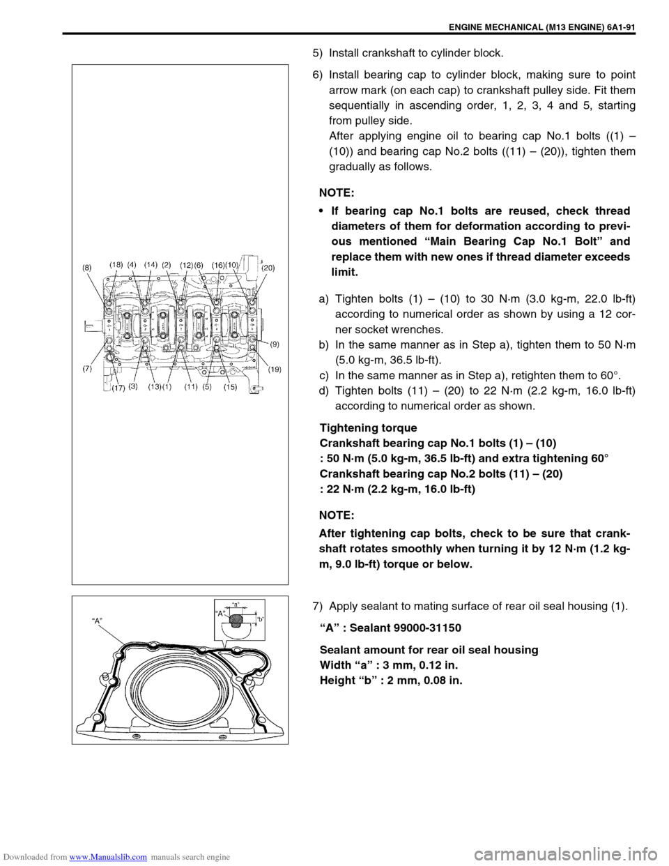
6) Install bearing cap to cylinder block, making sure to point
arrow mark (on each cap) to crankshaft pulley side. Fit them
sequentially in ascending order, 1, 2, 3, 4 and 5, starting
from pulley side.
After applying engine oil to bearing cap No.1 bolts ((1) –
(10)) and bearing cap No.2 bolts ((11) – (20)), tighten them
gradually as follows.
a) Tighten bolts (1) – (10) to 30 N·m (3.0 kg-m, 22.0 lb-ft)
according to numerical order as shown by using a 12 cor-
ner socket wrenches.
b) In the same manner as in Step a), tighten them to 50 N·m
(5.0 kg-m, 36.5 lb-ft).
c) In the same manner as in Step a), retighten them to 60°.
d) Tighten bolts (11) – (20) to 22 N·m (2.2 kg-m, 16.0 lb-ft)
according to numerical order as shown.
Tightening torque
Crankshaft bearing cap No.1 bolts (1) – (10)
: 50 N·m (5.0 kg-m, 36.5 lb-ft) and extra tightening 60°
Crankshaft bearing cap No.2 bolts (11) – (20)
: 22 N·m (2.2 kg-m, 16.0 lb-ft)
7) Apply sealant to mating surface of rear oil seal housing (1).
“A” : Sealant 99000-31150
Sealant amount for rear oil seal housing
Width “a” : 3 mm, 0.12 in.
Height “b” : 2 mm, 0.08 in. NOTE:
If bearing cap No.1 bolts are reused, check thread
diameters of them for deformation according to previ-
ous mentioned “Main Bearing Cap No.1 Bolt” and
replace them with new ones if thread diameter exceeds
limit.
NOTE:
After tightening cap bolts, check to be sure that crank-
shaft rotates smoothly when turning it by 12 N·m (1.2 kg-
m, 9.0 lb-ft) torque or below.
Page 580 of 687
Downloaded from www.Manualslib.com manuals search engine ENGINE COOLING 6B-3
Radiator Cap
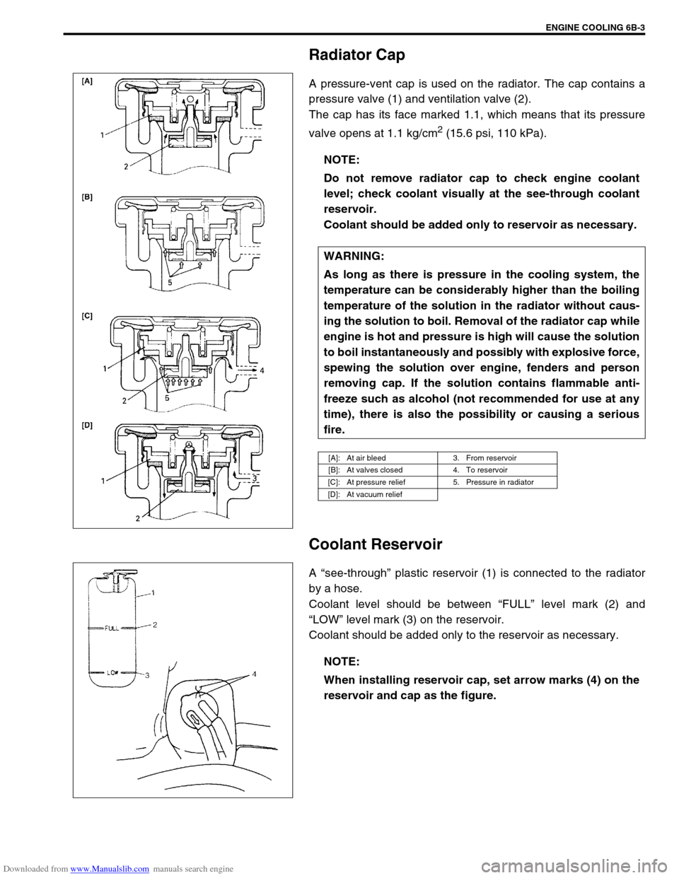
A pressure-vent cap is used on the radiator. The cap contains a
pressure valve (1) and ventilation valve (2).
The cap has its face marked 1.1, which means that its pressure
valve opens at 1.1 kg/cm
2 (15.6 psi, 110 kPa).
Coolant Reservoir
A “see-through” plastic reservoir (1) is connected to the radiator
by a hose.
Coolant level should be between “FULL” level mark (2) and
“LOW” level mark (3) on the reservoir.
Coolant should be added only to the reservoir as necessary.NOTE:
Do not remove radiator cap to check engine coolant
level; check coolant visually at the see-through coolant
reservoir.
Coolant should be added only to reservoir as necessary.
WARNING:
As long as there is pressure in the cooling system, the
temperature can be considerably higher than the boiling
temperature of the solution in the radiator without caus-
ing the solution to boil. Removal of the radiator cap while
engine is hot and pressure is high will cause the solution
to boil instantaneously and possibly with explosive force,
spewing the solution over engine, fenders and person
removing cap. If the solution contains flammable anti-
freeze such as alcohol (not recommended for use at any
time), there is also the possibility or causing a serious
fire.
[A]: At air bleed 3. From reservoir
[B]: At valves closed 4. To reservoir
[C]: At pressure relief 5. Pressure in radiator
[D]: At vacuum relief
NOTE:
When installing reservoir cap, set arrow marks (4) on the
reservoir and cap as the figure.
Page 582 of 687
Downloaded from www.Manualslib.com manuals search engine ENGINE COOLING 6B-5
Diagnosis
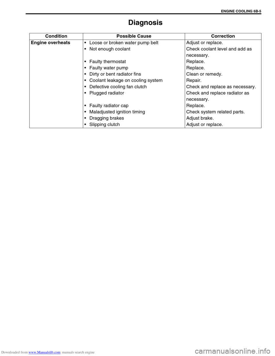
Condition Possible Cause Correction
Engine overheats
Loose or broken water pump belt
Not enough coolant
Faulty thermostat
Faulty water pump
Dirty or bent radiator fins
Coolant leakage on cooling system
Defective cooling fan clutch
Plugged radiator
Faulty radiator cap
Maladjusted ignition timing
Dragging brakes
Slipping clutchAdjust or replace.
Check coolant level and add as
necessary.
Replace.
Replace.
Clean or remedy.
Repair.
Check and replace as necessary.
Check and replace radiator as
necessary.
Replace.
Check system related parts.
Adjust brake.
Adjust or replace.
Page 584 of 687
Downloaded from www.Manualslib.com manuals search engine ENGINE COOLING 6B-7
Coolant Level
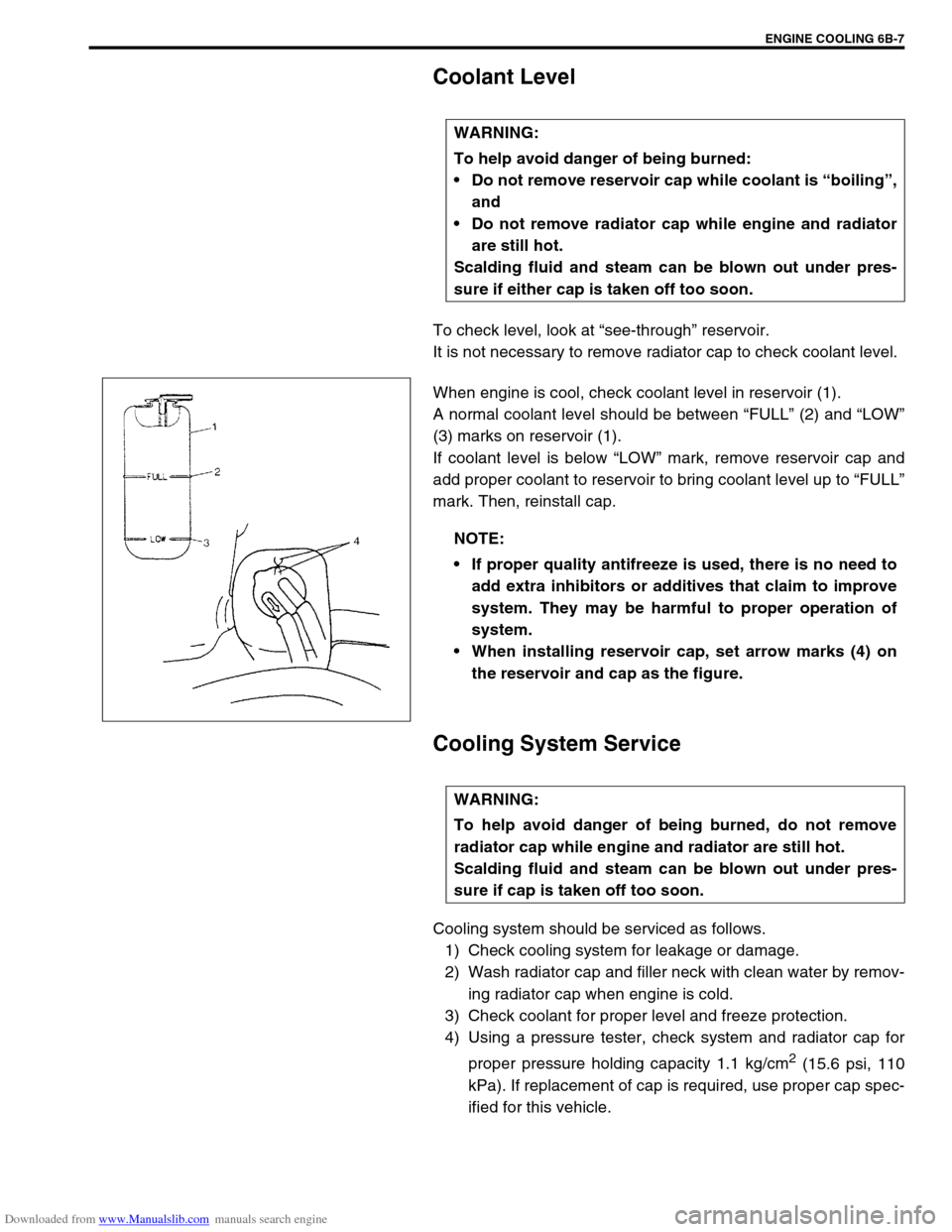
To check level, look at “see-through” reservoir.
It is not necessary to remove radiator cap to check coolant level.
When engine is cool, check coolant level in reservoir (1).
A normal coolant level should be between “FULL” (2) and “LOW”
(3) marks on reservoir (1).
If coolant level is below “LOW” mark, remove reservoir cap and
add proper coolant to reservoir to bring coolant level up to “FULL”
mark. Then, reinstall cap.
Cooling System Service
Cooling system should be serviced as follows.
1) Check cooling system for leakage or damage.
2) Wash radiator cap and filler neck with clean water by remov-
ing radiator cap when engine is cold.
3) Check coolant for proper level and freeze protection.
4) Using a pressure tester, check system and radiator cap for
proper pressure holding capacity 1.1 kg/cm
2 (15.6 psi, 110
kPa). If replacement of cap is required, use proper cap spec-
ified for this vehicle. WARNING:
To help avoid danger of being burned:
Do not remove reservoir cap while coolant is “boiling”,
and
Do not remove radiator cap while engine and radiator
are still hot.
Scalding fluid and steam can be blown out under pres-
sure if either cap is taken off too soon.
NOTE:
If proper quality antifreeze is used, there is no need to
add extra inhibitors or additives that claim to improve
system. They may be harmful to proper operation of
system.
When installing reservoir cap, set arrow marks (4) on
the reservoir and cap as the figure.
WARNING:
To help avoid danger of being burned, do not remove
radiator cap while engine and radiator are still hot.
Scalding fluid and steam can be blown out under pres-
sure if cap is taken off too soon.
Page 586 of 687
Downloaded from www.Manualslib.com manuals search engine ENGINE COOLING 6B-9
9) Run engine, with radiator cap removed, until radiator upper
hose is hot.
10) With engine idling, add coolant to radiator until level reaches
the bottom of filler neck. Install radiator cap, making sure
that the ear of cap lines up with reservoir hose.
Water Pump Belt Tension
1) Inspect belt for cracks, cuts, deformation, wear and cleanli-
ness. If it is necessary to replace belt, refer to “Water Pump
Belt and Cooling Fan” in this section.
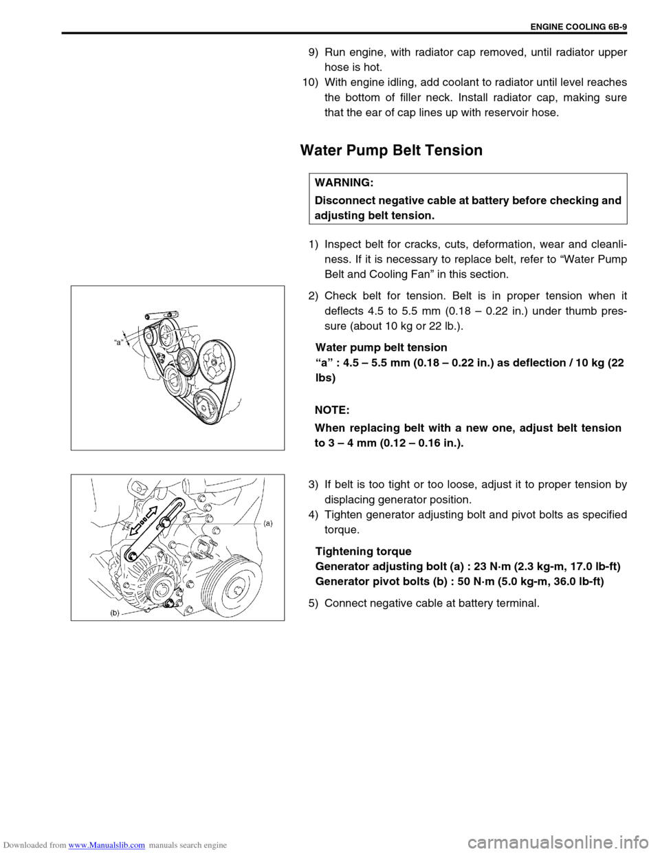
2) Check belt for tension. Belt is in proper tension when it
deflects 4.5 to 5.5 mm (0.18 – 0.22 in.) under thumb pres-
sure (about 10 kg or 22 lb.).
Water pump belt tension
“a” : 4.5 – 5.5 mm (0.18 – 0.22 in.) as deflection / 10 kg (22
lbs)
3) If belt is too tight or too loose, adjust it to proper tension by
displacing generator position.
4) Tighten generator adjusting bolt and pivot bolts as specified
torque.
Tightening torque
Generator adjusting bolt (a) : 23 N·m (2.3 kg-m, 17.0 lb-ft)
Generator pivot bolts (b) : 50 N·m (5.0 kg-m, 36.0 lb-ft)
5) Connect negative cable at battery terminal.WARNING:
Disconnect negative cable at battery before checking and
adjusting belt tension.
NOTE:
When replacing belt with a new one, adjust belt tension
to 3 – 4 mm (0.12 – 0.16 in.).