ect SUZUKI JIMNY 2005 3.G Service Workshop Manual
[x] Cancel search | Manufacturer: SUZUKI, Model Year: 2005, Model line: JIMNY, Model: SUZUKI JIMNY 2005 3.GPages: 687, PDF Size: 13.38 MB
Page 552 of 687
Downloaded from www.Manualslib.com manuals search engine ENGINE MECHANICAL (M13 ENGINE) 6A1-71
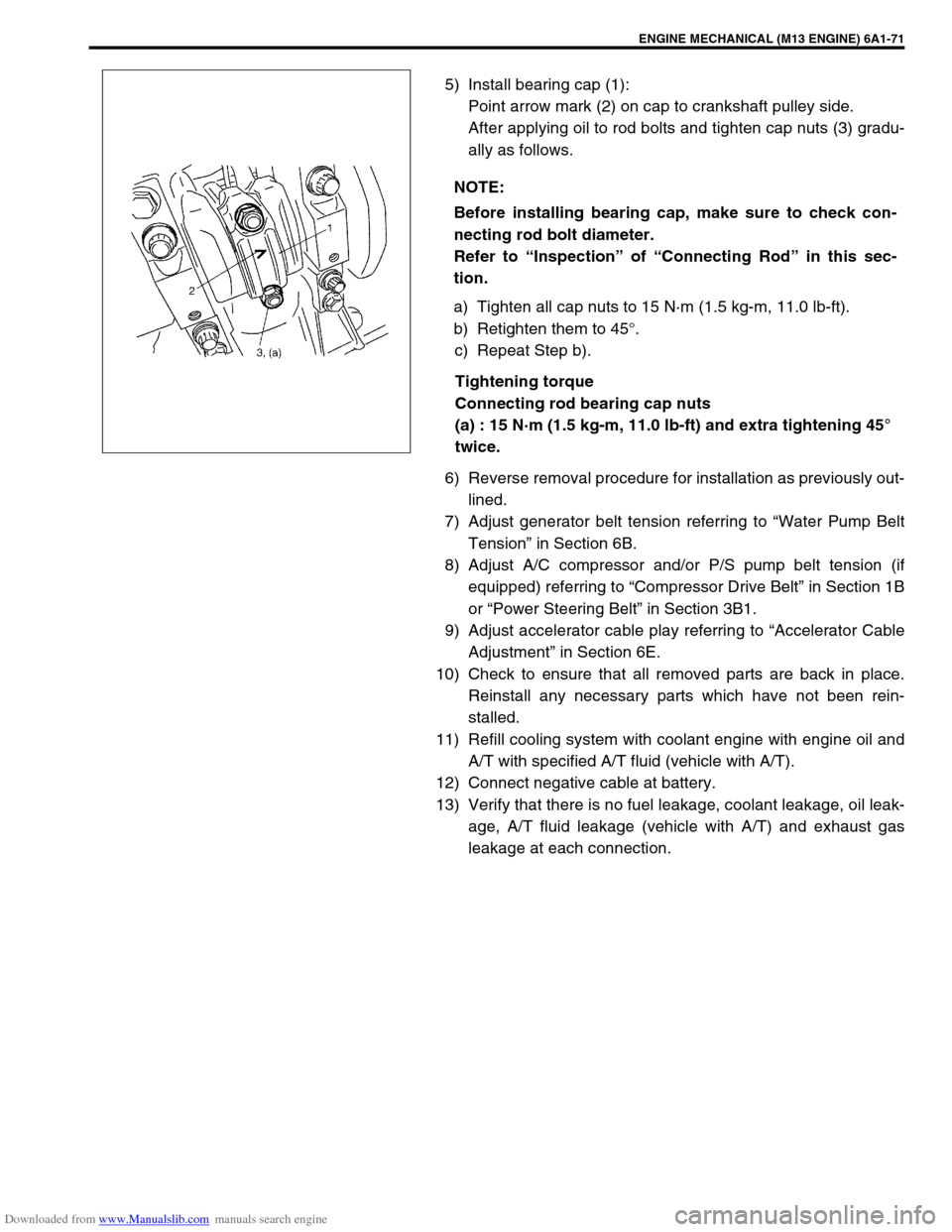
5) Install bearing cap (1):
Point arrow mark (2) on cap to crankshaft pulley side.
After applying oil to rod bolts and tighten cap nuts (3) gradu-
ally as follows.
a) Tighten all cap nuts to 15 N·m (1.5 kg-m, 11.0 lb-ft).
b) Retighten them to 45°.
c) Repeat Step b).
Tightening torque
Connecting rod bearing cap nuts
(a) : 15 N·m (1.5 kg-m, 11.0 lb-ft) and extra tightening 45°
twice.
6) Reverse removal procedure for installation as previously out-
lined.
7) Adjust generator belt tension referring to “Water Pump Belt
Tension” in Section 6B.
8) Adjust A/C compressor and/or P/S pump belt tension (if
equipped) referring to “Compressor Drive Belt” in Section 1B
or “Power Steering Belt” in Section 3B1.
9) Adjust accelerator cable play referring to “Accelerator Cable
Adjustment” in Section 6E.
10) Check to ensure that all removed parts are back in place.
Reinstall any necessary parts which have not been rein-
stalled.
11) Refill cooling system with coolant engine with engine oil and
A/T with specified A/T fluid (vehicle with A/T).
12) Connect negative cable at battery.
13) Verify that there is no fuel leakage, coolant leakage, oil leak-
age, A/T fluid leakage (vehicle with A/T) and exhaust gas
leakage at each connection. NOTE:
Before installing bearing cap, make sure to check con-
necting rod bolt diameter.
Refer to “Inspection” of “Connecting Rod” in this sec-
tion.
Page 554 of 687
Downloaded from www.Manualslib.com manuals search engine ENGINE MECHANICAL (M13 ENGINE) 6A1-73
Unit Repair Overhaul
Engine Assembly
REMOVAL
1) Relieve fuel pressure referring to “Fuel Pressure Relief Pro-
cedure” in Section 6.
2) Disconnect negative cable at battery.
3) Remove engine hood after disconnecting windshield washer
hose.
4) Remove A/C compressor and/or P/S pump belt (if
equipped).
5) Remove generator belt.
6) Drain engine oil.
7) Drain coolant.
8) Disconnect radiator inlet and outlet hoses from each pipe.
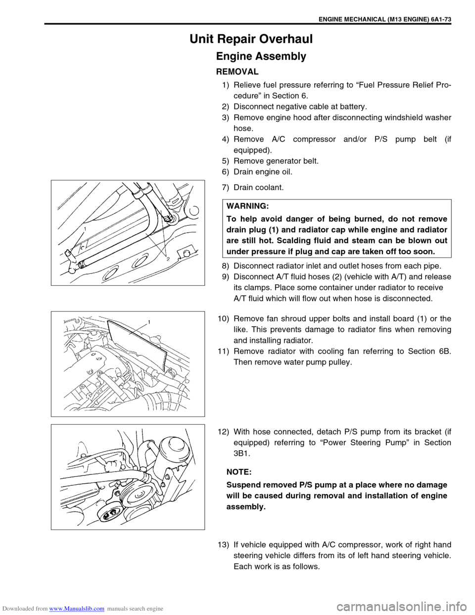
9) Disconnect A/T fluid hoses (2) (vehicle with A/T) and release
its clamps. Place some container under radiator to receive
A/T fluid which will flow out when hose is disconnected.
10) Remove fan shroud upper bolts and install board (1) or the
like. This prevents damage to radiator fins when removing
and installing radiator.
11) Remove radiator with cooling fan referring to Section 6B.
Then remove water pump pulley.
12) With hose connected, detach P/S pump from its bracket (if
equipped) referring to “Power Steering Pump” in Section
3B1.
13) If vehicle equipped with A/C compressor, work of right hand
steering vehicle differs from its of left hand steering vehicle.
Each work is as follows. WARNING:
To help avoid danger of being burned, do not remove
drain plug (1) and radiator cap while engine and radiator
are still hot. Scalding fluid and steam can be blown out
under pressure if plug and cap are taken off too soon.
NOTE:
Suspend removed P/S pump at a place where no damage
will be caused during removal and installation of engine
assembly.
Page 555 of 687
Downloaded from www.Manualslib.com manuals search engine 6A1-74 ENGINE MECHANICAL (M13 ENGINE)
a) For right hand steering vehicle:
With hose connected, detach A/C compressor from its
bracket.
b) For left hand steering vehicle:
i) Recover refrigerant from refrigeration system using recov-
ery and recycling equipment.
ii) Disconnect magnet clutch lead wire.
iii) Remove suction pipe and disconnect discharge pipe from
A/C compressor.
iv) Remove A/C compressor from its bracket.
When servicing above steps, refer to “Compressor” in Section 1B.
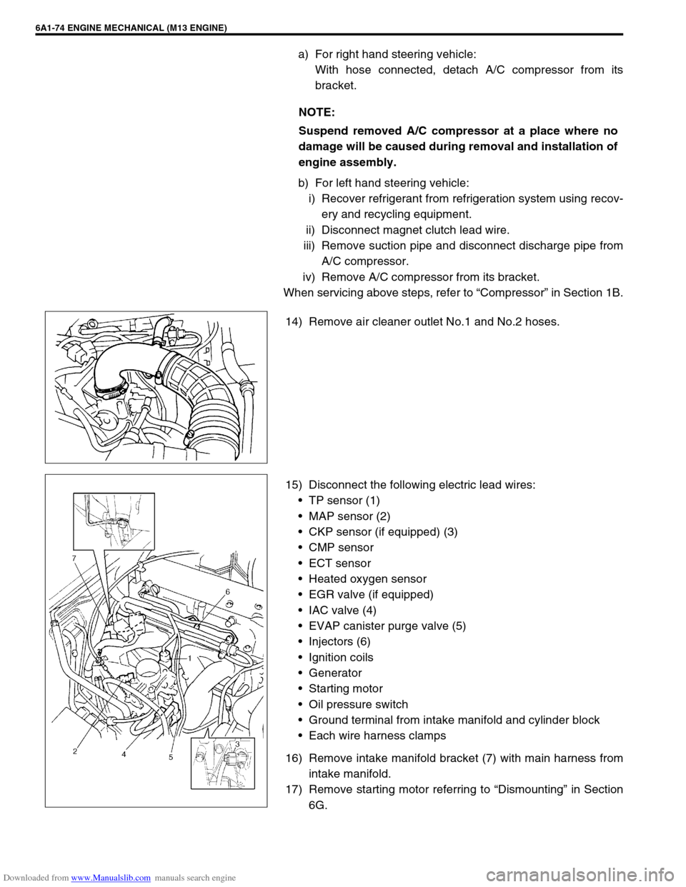
14) Remove air cleaner outlet No.1 and No.2 hoses.
15) Disconnect the following electric lead wires:
TP sensor (1)
MAP sensor (2)
CKP sensor (if equipped) (3)
CMP sensor
ECT sensor
Heated oxygen sensor
EGR valve (if equipped)
IAC valve (4)
EVAP canister purge valve (5)
Injectors (6)
Ignition coils
Generator
Starting motor
Oil pressure switch
Ground terminal from intake manifold and cylinder block
Each wire harness clamps
16) Remove intake manifold bracket (7) with main harness from
intake manifold.
17) Remove starting motor referring to “Dismounting” in Section
6G. NOTE:
Suspend removed A/C compressor at a place where no
damage will be caused during removal and installation of
engine assembly.
Page 556 of 687
Downloaded from www.Manualslib.com manuals search engine ENGINE MECHANICAL (M13 ENGINE) 6A1-75
18) Remove heated oxygen sensor bracket from cylinder head
and detach No.1 heated oxygen sensor coupler from its
bracket.
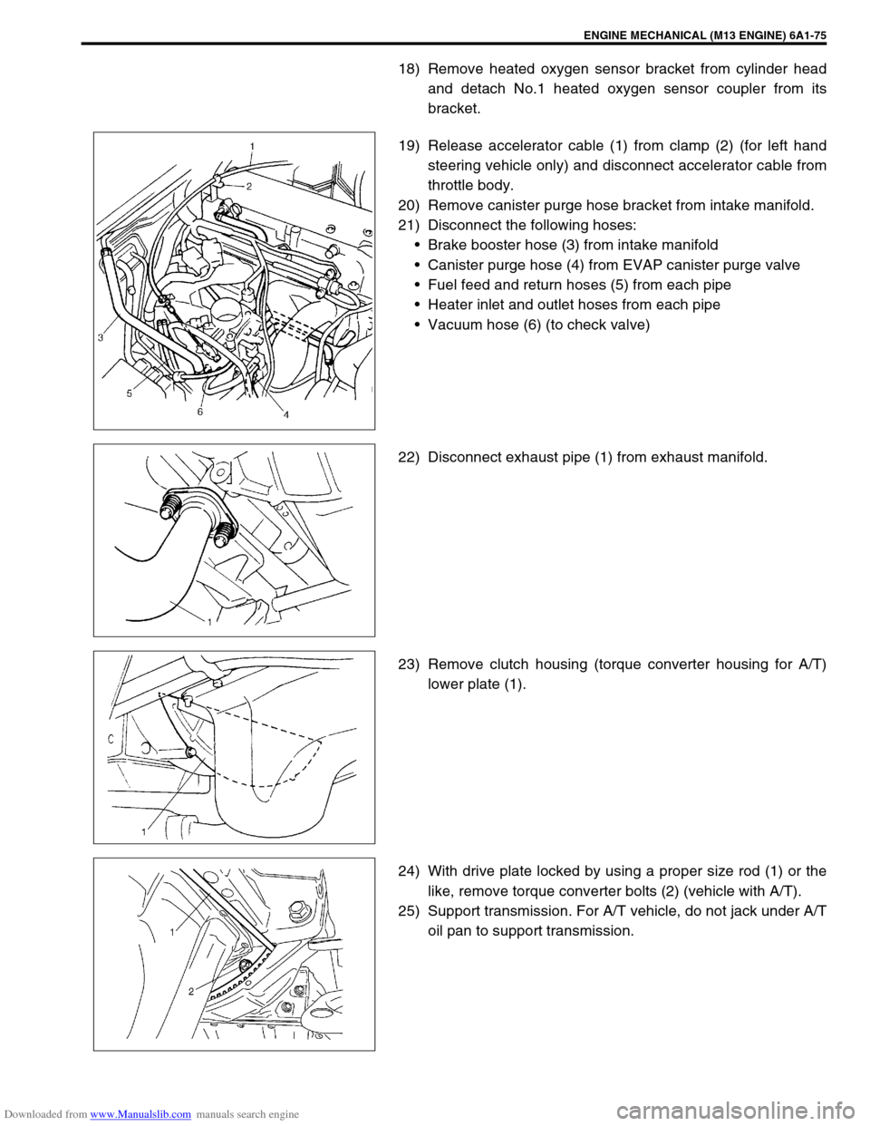
19) Release accelerator cable (1) from clamp (2) (for left hand
steering vehicle only) and disconnect accelerator cable from
throttle body.
20) Remove canister purge hose bracket from intake manifold.
21) Disconnect the following hoses:
Brake booster hose (3) from intake manifold
Canister purge hose (4) from EVAP canister purge valve
Fuel feed and return hoses (5) from each pipe
Heater inlet and outlet hoses from each pipe
Vacuum hose (6) (to check valve)
22) Disconnect exhaust pipe (1) from exhaust manifold.
23) Remove clutch housing (torque converter housing for A/T)
lower plate (1).
24) With drive plate locked by using a proper size rod (1) or the
like, remove torque converter bolts (2) (vehicle with A/T).
25) Support transmission. For A/T vehicle, do not jack under A/T
oil pan to support transmission.
Page 557 of 687
Downloaded from www.Manualslib.com manuals search engine 6A1-76 ENGINE MECHANICAL (M13 ENGINE)
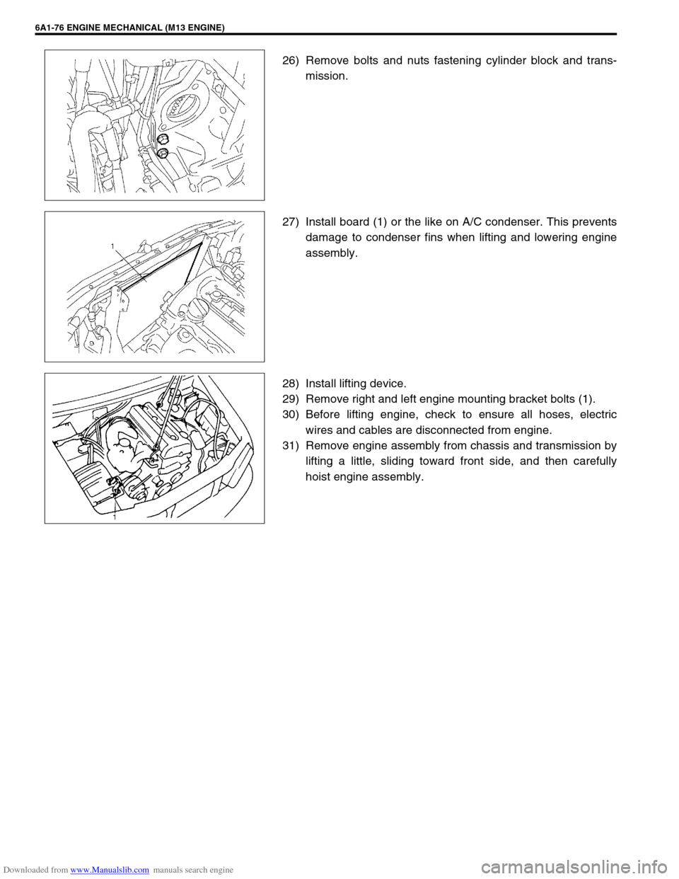
26) Remove bolts and nuts fastening cylinder block and trans-
mission.
27) Install board (1) or the like on A/C condenser. This prevents
damage to condenser fins when lifting and lowering engine
assembly.
28) Install lifting device.
29) Remove right and left engine mounting bracket bolts (1).
30) Before lifting engine, check to ensure all hoses, electric
wires and cables are disconnected from engine.
31) Remove engine assembly from chassis and transmission by
lifting a little, sliding toward front side, and then carefully
hoist engine assembly.
Page 558 of 687

Downloaded from www.Manualslib.com manuals search engine ENGINE MECHANICAL (M13 ENGINE) 6A1-77
INSTALLATION
1) Lower engine assembly into engine compartment.
Connect engine to transmission.
Hard-tighten bolts and nuts fastening cylinder block and
transmission.
2) Tighten right and left engine mounting bracket bolts to speci-
fied torque.
Tightening torque
Engine mounting bracket bolts
(a) : 50 N·m (5.0 kg-m, 36.5 lb-ft)
3) Tighten bolts and nuts fastening cylinder block and transmis-
sion to specified torque.
Tightening torque
Vehicle with M/T
Cylinder block and transmission fastening bolts and nuts
(a) : 94 N·m (9.4 kg-m, 68.0 lb-ft)
Vehicle with A/T
Cylinder block and transmission fastening bolts and nuts
(a) : 80 N·m (8.0 kg-m, 58.0 lb-ft)
4) Remove lifting device.
5) Reverse removal procedure for installation, noting the follow-
ing points.
Tighten torque converter bolts to specified torque (vehicle
with A/T).
Tightening torque
Torque converter bolts (a) : 20 N·m (2.0 kg-m, 14.5 lb-ft)
Page 559 of 687
Downloaded from www.Manualslib.com manuals search engine 6A1-78 ENGINE MECHANICAL (M13 ENGINE)
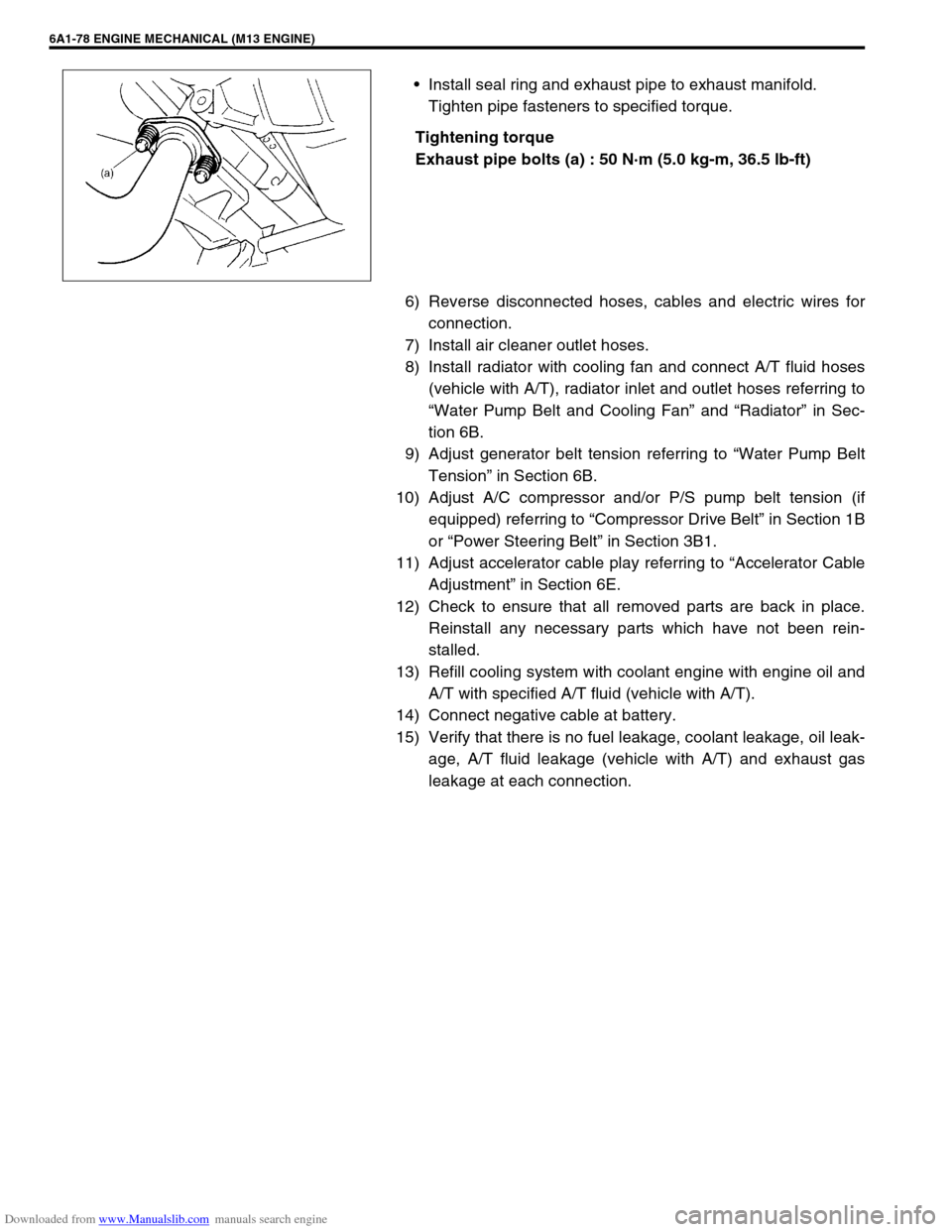
Install seal ring and exhaust pipe to exhaust manifold.
Tighten pipe fasteners to specified torque.
Tightening torque
Exhaust pipe bolts (a) : 50 N·m (5.0 kg-m, 36.5 lb-ft)
6) Reverse disconnected hoses, cables and electric wires for
connection.
7) Install air cleaner outlet hoses.
8) Install radiator with cooling fan and connect A/T fluid hoses
(vehicle with A/T), radiator inlet and outlet hoses referring to
“Water Pump Belt and Cooling Fan” and “Radiator” in Sec-
tion 6B.
9) Adjust generator belt tension referring to “Water Pump Belt
Tension” in Section 6B.
10) Adjust A/C compressor and/or P/S pump belt tension (if
equipped) referring to “Compressor Drive Belt” in Section 1B
or “Power Steering Belt” in Section 3B1.
11) Adjust accelerator cable play referring to “Accelerator Cable
Adjustment” in Section 6E.
12) Check to ensure that all removed parts are back in place.
Reinstall any necessary parts which have not been rein-
stalled.
13) Refill cooling system with coolant engine with engine oil and
A/T with specified A/T fluid (vehicle with A/T).
14) Connect negative cable at battery.
15) Verify that there is no fuel leakage, coolant leakage, oil leak-
age, A/T fluid leakage (vehicle with A/T) and exhaust gas
leakage at each connection.
Page 561 of 687

Downloaded from www.Manualslib.com manuals search engine 6A1-80 ENGINE MECHANICAL (M13 ENGINE)
REMOVAL
1) Remove engine assembly from vehicle as previously out-
lined.
2) Remove clutch cover, clutch disc and flywheel (drive plate
for A/T) by using special tool.
Special tool
(A) : 09924-17810
3) Remove the following parts from engine as previously out-
lined.
Oil pan and oil pump strainer
Intake manifold and exhaust manifold
Cylinder head cover
Timing chain cover
Timing chain guide, chain tensioner adjuster, chain ten-
sioner, timing chain and crankshaft timing sprocket
Camshaft, tappet and shim
Cylinder head assembly
Piston and connecting rod
4) Remove rear oil seal housing (1).
5) Loosen bearing cap No.1 and No.2 bolts in such order as
indicated in figure and remove them.
6) Remove crankshaft from cylinder block.
Page 562 of 687

Downloaded from www.Manualslib.com manuals search engine ENGINE MECHANICAL (M13 ENGINE) 6A1-81
INSPECTION
Main bearing cap No.1 bolt
Measure each thread diameter of bearing cap No.1 bolts (1) at
“A” on 60 mm (2.36 in.) from seat side of flange bolt and “B” on 90
mm (3.54 in.) from seat side of flange bolt by using a micrometer
(2).
Calculate difference in diameters (“A” – “B”).
If it exceeds limit, replace with new one.
Bearing cap No.1 bolt diameter measurement points
“a” : 60 mm (2.36 in.)
“b” : 90 mm (3.54 in.)
Bearing cap No.1 bolt diameter difference
Limit (“A” – “B”) : 0.2 mm (0.008 in.)
Crankshaft
Crankshaft runout
Using a dial gauge, measure runout at center journal. Rotate
crankshaft slowly. If runout exceeds its limit, replace crankshaft.
Crankshaft runout
Limit : 0.04 mm (0.0016 in.)
Crankshaft thrust play
Measure this play with crankshaft set in cylinder block in the nor-
mal manner, that is with thrust bearing (1) and journal bearing
caps installed.
Thickness of crankshaft thrust bearing
Standard : 2.500 mm (0.0984 in.)
Oversize (0.125 mm (0.0049 in.)) : 2.563 mm (0.1009 in.)
“A”
“a”
“b”“B”
1
1
2
Page 563 of 687

Downloaded from www.Manualslib.com manuals search engine 6A1-82 ENGINE MECHANICAL (M13 ENGINE)
Tighten bearing cap No.1 bolts (1) – (10) and No.2 bolts (11) –
(20) gradually as follows.
1) Tighten bolts (1) – (10) to 30 N·m (3.0 kg-m, 22.0 lb-ft)
according to numerical order in figure.
2) In the same manner as in Step 1), tighten them to 50 N·m
(5.0 kg-m, 36.5 lb-ft).
3) In the same manner as in step 1), retighten them to 60°.
4) Tighten bolts (11) – (20) to 22 N·m (2.2 kg-m, 16.0 lb-ft)
according to numerical order in figure.
Tightening torque
Crankshaft bearing cap No.1 bolts (1) – (10) :
50 N·m (5.0 kg-m, 36.5 lb-ft) and extra tightening 60°
Crankshaft bearing cap No.2 bolts (11) – (20) :
22 N·m (2.2 kg-m, 16.0 lb-ft)
Use a dial gauge to read displacement in axial (thrust) direction of
crankshaft.
If its limit is exceeded, replace thrust bearing with new standard
one or oversize one to obtain standard thrust play.
Crankshaft thrust play
Standard : 0.11 – 0.31 mm (0.0043 – 0.0122 in.)
Limit : 0.35 mm (0.0138 in.)
Out-of-round and taper of journals
An unevenly worn crankshaft journal shows up as a difference in
diameter at a cross section or along its length (or both). This dif-
ference, if any, is determined by taking micrometer readings. If
any one of journals is badly damaged or if amount of uneven
wear in the sense explained above exceeds its limit, regrind or
replace crankshaft.
Crankshaft out-of-round and taper
Limit : 0.01 mm (0.0004 in.)
Out-of-round : A – B
Taper : a – b
Main Bearings
General information
Service main bearings are available in standard size and
0.25 mm (0.0098 in.) undersize, and each of them has 5
kinds of bearings differing in tolerance.
NOTE:
After checking the thrust play, check for thread deforma-
tion of each bearing cap No.1 bolt according to previous
mentioned “Main Bearing Cap No.1 Bolt” once again.